2002 DODGE RAM warning
[x] Cancel search: warningPage 1969 of 2255
DIAGNOSIS AND TESTING
DIAGNOSIS AND TESTING - WATER LEAKS
Water leaks can be caused by poor sealing,
improper body component alignment, body seam
porosity, missing plugs, or blocked drain holes. Cen-
trifugal and gravitational force can cause water to
drip from a location away from the actual leak point,
making leak detection difficult. All body sealing
points should be water tight in normal wet-driving
conditions. Water flowing downward from the front of
the vehicle should not enter the passenger or luggage
compartment. Moving sealing surfaces will not
always seal water tight under all conditions. At
times, side glass or door seals will allow water to
enter the passenger compartment during high pres-
sure washing or hard driving rain (severe) condi-
tions. Overcompensating on door or glass
adjustments to stop a water leak that occurs under
severe conditions can cause premature seal wear and
excessive closing or latching effort. After completing
a repair, water test vehicle to verify leak has stopped
before returning vehicle to use.
VISUAL INSPECTION BEFORE WATER LEAK TESTS
Verify that floor and body plugs are in place, body
drains are clear, and body components are properly
aligned and sealed. If component alignment or seal-
ing is necessary, refer to the appropriate section of
this group for proper procedures.
WATER LEAK TESTS
WARNING: DO NOT USE ELECTRIC SHOP LIGHTS
OR TOOLS IN WATER TEST AREA. PERSONAL
INJURY CAN RESULT.
When the conditions causing a water leak have
been determined, simulate the conditions as closely
as possible.
²If a leak occurs with the vehicle parked in a
steady light rain, flood the leak area with an open-
ended garden hose.²If a leak occurs while driving at highway speeds
in a steady rain, test the leak area with a reasonable
velocity stream or fan spray of water. Direct the
spray in a direction comparable to actual conditions.
²If a leak occurs when the vehicle is parked on an
incline, hoist the end or side of the vehicle to simu-
late this condition. This method can be used when
the leak occurs when the vehicle accelerates, stops or
turns. If the leak occurs on acceleration, hoist the
front of the vehicle. If the leak occurs when braking,
hoist the back of the vehicle. If the leak occurs on left
turns, hoist the left side of the vehicle. If the leak
occurs on right turns, hoist the right side of the vehi-
cle. For hoisting recommendations refer to Group 0,
Lubrication and Maintenance, General Information
section.
WATER LEAK DETECTION
To detect a water leak point-of-entry, do a water
test and watch for water tracks or droplets forming
on the inside of the vehicle. If necessary, remove inte-
rior trim covers or panels to gain visual access to the
leak area. If the hose cannot be positioned without
being held, have someone help do the water test.
Some water leaks must be tested for a considerable
length of time to become apparent. When a leak
appears, find the highest point of the water track or
drop. The highest point usually will show the point of
entry. After leak point has been found, repair the
leak and water test to verify that the leak has
stopped.
Locating the entry point of water that is leaking
into a cavity between panels can be difficult. The
trapped water may splash or run from the cavity,
often at a distance from the entry point. Most water
leaks of this type become apparent after accelerating,
stopping, turning, or when on an incline.
MIRROR INSPECTION METHOD
When a leak point area is visually obstructed, use
a suitable mirror to gain visual access. A mirror can
also be used to deflect light to a limited-access area
to assist in locating a leak point.
23 - 2 BODYBR/BE
BODY (Continued)
Page 2065 of 2255
INSTALLATION
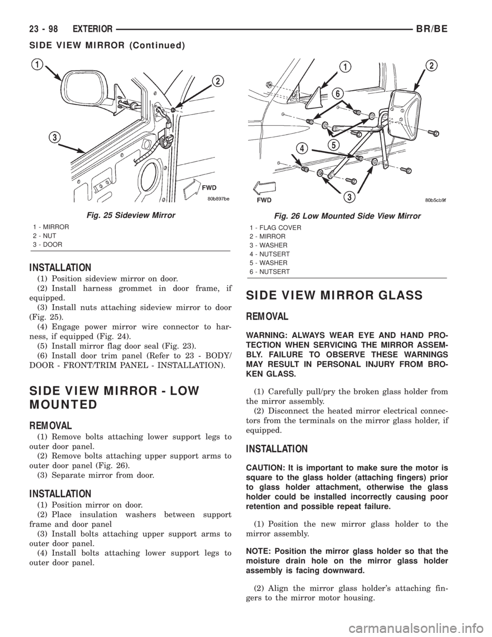
(1) Position sideview mirror on door.
(2) Install harness grommet in door frame, if
equipped.
(3) Install nuts attaching sideview mirror to door
(Fig. 25).
(4) Engage power mirror wire connector to har-
ness, if equipped (Fig. 24).
(5) Install mirror flag door seal (Fig. 23).
(6) Install door trim panel (Refer to 23 - BODY/
DOOR - FRONT/TRIM PANEL - INSTALLATION).
SIDE VIEW MIRROR - LOW
MOUNTED
REMOVAL
(1) Remove bolts attaching lower support legs to
outer door panel.
(2) Remove bolts attaching upper support arms to
outer door panel (Fig. 26).
(3) Separate mirror from door.
INSTALLATION
(1) Position mirror on door.
(2) Place insulation washers between support
frame and door panel
(3) Install bolts attaching upper support arms to
outer door panel.
(4) Install bolts attaching lower support legs to
outer door panel.
SIDE VIEW MIRROR GLASS
REMOVAL
WARNING: ALWAYS WEAR EYE AND HAND PRO-
TECTION WHEN SERVICING THE MIRROR ASSEM-
BLY. FAILURE TO OBSERVE THESE WARNINGS
MAY RESULT IN PERSONAL INJURY FROM BRO-
KEN GLASS.
(1) Carefully pull/pry the broken glass holder from
the mirror assembly.
(2) Disconnect the heated mirror electrical connec-
tors from the terminals on the mirror glass holder, if
equipped.
INSTALLATION
CAUTION: It is important to make sure the motor is
square to the glass holder (attaching fingers) prior
to glass holder attachment, otherwise the glass
holder could be installed incorrectly causing poor
retention and possible repeat failure.
(1) Position the new mirror glass holder to the
mirror assembly.
NOTE: Position the mirror glass holder so that the
moisture drain hole on the mirror glass holder
assembly is facing downward.
(2) Align the mirror glass holder's attaching fin-
gers to the mirror motor housing.
Fig. 25 Sideview Mirror
1 - MIRROR
2 - NUT
3 - DOOR
Fig. 26 Low Mounted Side View Mirror
1 - FLAG COVER
2 - MIRROR
3 - WASHER
4 - NUTSERT
5 - WASHER
6 - NUTSERT
23 - 98 EXTERIORBR/BE
SIDE VIEW MIRROR (Continued)
Page 2074 of 2255
ASH RECEIVER
REMOVAL
WARNING: ON VEHICLES EQUIPPED WITH AIR-
BAGS, DISABLE THE AIRBAG SYSTEM BEFORE
ATTEMPTING ANY STEERING WHEEL, STEERING
COLUMN, SEAT BELT TENSIONER, OR INSTRU-
MENT PANEL COMPONENT DIAGNOSIS OR SER-
VICE. DISCONNECT AND ISOLATE THE BATTERY
NEGATIVE (GROUND) CABLE, THEN WAIT TWO
MINUTES FOR THE AIRBAG SYSTEM CAPACITOR
TO DISCHARGE BEFORE PERFORMING FURTHER
DIAGNOSIS OR SERVICE. THIS IS THE ONLY SURE
WAY TO DISABLE THE AIRBAG SYSTEM. FAILURE
TO TAKE THE PROPER PRECAUTIONS COULD
RESULT IN ACCIDENTAL AIRBAG DEPLOYMENT
AND POSSIBLE PERSONAL INJURY.
(1) Disconnect and isolate the battery negative
cable.
(2) Open the instrument panel ash receiver.
(3) From the open position, close the ash receiver
slightly and pull it straight back far enough to disen-
gage it from the pivot pins in the lower instrument
panel.
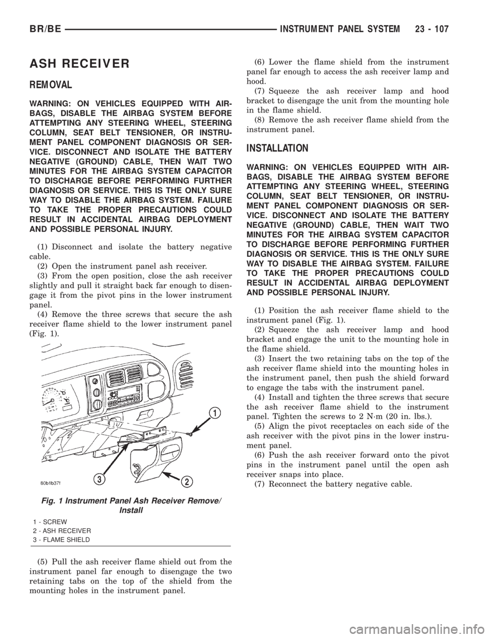
(4) Remove the three screws that secure the ash
receiver flame shield to the lower instrument panel
(Fig. 1).
(5) Pull the ash receiver flame shield out from the
instrument panel far enough to disengage the two
retaining tabs on the top of the shield from the
mounting holes in the instrument panel.(6) Lower the flame shield from the instrument
panel far enough to access the ash receiver lamp and
hood.
(7) Squeeze the ash receiver lamp and hood
bracket to disengage the unit from the mounting hole
in the flame shield.
(8) Remove the ash receiver flame shield from the
instrument panel.
INSTALLATION
WARNING: ON VEHICLES EQUIPPED WITH AIR-
BAGS, DISABLE THE AIRBAG SYSTEM BEFORE
ATTEMPTING ANY STEERING WHEEL, STEERING
COLUMN, SEAT BELT TENSIONER, OR INSTRU-
MENT PANEL COMPONENT DIAGNOSIS OR SER-
VICE. DISCONNECT AND ISOLATE THE BATTERY
NEGATIVE (GROUND) CABLE, THEN WAIT TWO
MINUTES FOR THE AIRBAG SYSTEM CAPACITOR
TO DISCHARGE BEFORE PERFORMING FURTHER
DIAGNOSIS OR SERVICE. THIS IS THE ONLY SURE
WAY TO DISABLE THE AIRBAG SYSTEM. FAILURE
TO TAKE THE PROPER PRECAUTIONS COULD
RESULT IN ACCIDENTAL AIRBAG DEPLOYMENT
AND POSSIBLE PERSONAL INJURY.
(1) Position the ash receiver flame shield to the
instrument panel (Fig. 1).
(2) Squeeze the ash receiver lamp and hood
bracket and engage the unit to the mounting hole in
the flame shield.
(3) Insert the two retaining tabs on the top of the
ash receiver flame shield into the mounting holes in
the instrument panel, then push the shield forward
to engage the tabs with the instrument panel.
(4) Install and tighten the three screws that secure
the ash receiver flame shield to the instrument
panel. Tighten the screws to 2 N´m (20 in. lbs.).
(5) Align the pivot receptacles on each side of the
ash receiver with the pivot pins in the lower instru-
ment panel.
(6) Push the ash receiver forward onto the pivot
pins in the instrument panel until the open ash
receiver snaps into place.
(7) Reconnect the battery negative cable.
Fig. 1 Instrument Panel Ash Receiver Remove/
Install
1 - SCREW
2 - ASH RECEIVER
3 - FLAME SHIELD
BR/BEINSTRUMENT PANEL SYSTEM 23 - 107
Page 2075 of 2255
CLUSTER BEZEL
REMOVAL
WARNING: ON VEHICLES EQUIPPED WITH AIR-
BAGS, DISABLE THE AIRBAG SYSTEM BEFORE
ATTEMPTING ANY STEERING WHEEL, STEERING
COLUMN, SEAT BELT TENSIONER, OR INSTRU-
MENT PANEL COMPONENT DIAGNOSIS OR SER-
VICE. DISCONNECT AND ISOLATE THE BATTERY
NEGATIVE (GROUND) CABLE, THEN WAIT TWO
MINUTES FOR THE AIRBAG SYSTEM CAPACITOR
TO DISCHARGE BEFORE PERFORMING FURTHER
DIAGNOSIS OR SERVICE. THIS IS THE ONLY SURE
WAY TO DISABLE THE AIRBAG SYSTEM. FAILURE
TO TAKE THE PROPER PRECAUTIONS COULD
RESULT IN ACCIDENTAL AIRBAG DEPLOYMENT
AND POSSIBLE PERSONAL INJURY.
(1) Disconnect and isolate the battery negative
cable.
(2) If the vehicle is equipped with an automatic
transmission, turn the ignition switch to the Off posi-
tion (not Lock), set the parking brake, and place the
automatic transmission gear selector lever in the
Low position.
(3) If the vehicle is so equipped, set the tilt steer-
ing column in its lowest position.
(4) Using a trim stick or another suitable wide
flat-bladed tool, gently pry around the perimeter of
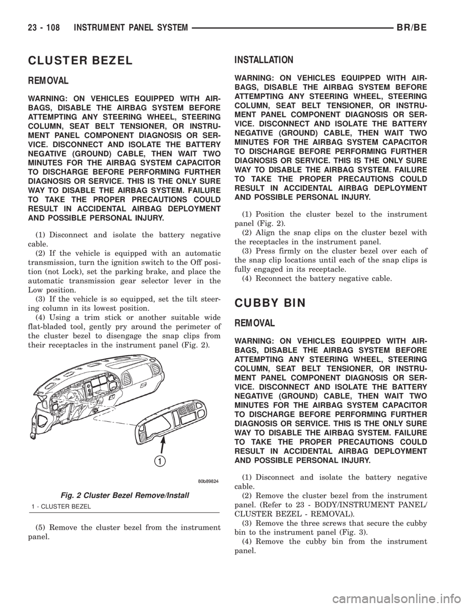
the cluster bezel to disengage the snap clips from
their receptacles in the instrument panel (Fig. 2).
(5) Remove the cluster bezel from the instrument
panel.
INSTALLATION
WARNING: ON VEHICLES EQUIPPED WITH AIR-
BAGS, DISABLE THE AIRBAG SYSTEM BEFORE
ATTEMPTING ANY STEERING WHEEL, STEERING
COLUMN, SEAT BELT TENSIONER, OR INSTRU-
MENT PANEL COMPONENT DIAGNOSIS OR SER-
VICE. DISCONNECT AND ISOLATE THE BATTERY
NEGATIVE (GROUND) CABLE, THEN WAIT TWO
MINUTES FOR THE AIRBAG SYSTEM CAPACITOR
TO DISCHARGE BEFORE PERFORMING FURTHER
DIAGNOSIS OR SERVICE. THIS IS THE ONLY SURE
WAY TO DISABLE THE AIRBAG SYSTEM. FAILURE
TO TAKE THE PROPER PRECAUTIONS COULD
RESULT IN ACCIDENTAL AIRBAG DEPLOYMENT
AND POSSIBLE PERSONAL INJURY.
(1) Position the cluster bezel to the instrument
panel (Fig. 2).
(2) Align the snap clips on the cluster bezel with
the receptacles in the instrument panel.
(3) Press firmly on the cluster bezel over each of
the snap clip locations until each of the snap clips is
fully engaged in its receptacle.
(4) Reconnect the battery negative cable.
CUBBY BIN
REMOVAL
WARNING: ON VEHICLES EQUIPPED WITH AIR-
BAGS, DISABLE THE AIRBAG SYSTEM BEFORE
ATTEMPTING ANY STEERING WHEEL, STEERING
COLUMN, SEAT BELT TENSIONER, OR INSTRU-
MENT PANEL COMPONENT DIAGNOSIS OR SER-
VICE. DISCONNECT AND ISOLATE THE BATTERY
NEGATIVE (GROUND) CABLE, THEN WAIT TWO
MINUTES FOR THE AIRBAG SYSTEM CAPACITOR
TO DISCHARGE BEFORE PERFORMING FURTHER
DIAGNOSIS OR SERVICE. THIS IS THE ONLY SURE
WAY TO DISABLE THE AIRBAG SYSTEM. FAILURE
TO TAKE THE PROPER PRECAUTIONS COULD
RESULT IN ACCIDENTAL AIRBAG DEPLOYMENT
AND POSSIBLE PERSONAL INJURY.
(1) Disconnect and isolate the battery negative
cable.
(2) Remove the cluster bezel from the instrument
panel. (Refer to 23 - BODY/INSTRUMENT PANEL/
CLUSTER BEZEL - REMOVAL).
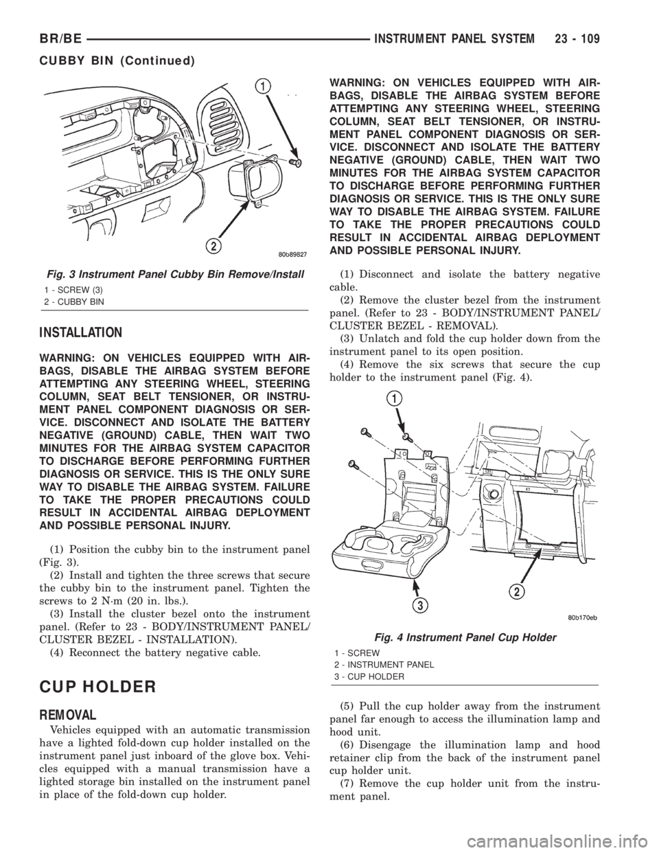
(3) Remove the three screws that secure the cubby
bin to the instrument panel (Fig. 3).
(4) Remove the cubby bin from the instrument
panel.
Fig. 2 Cluster Bezel Remove/Install
1 - CLUSTER BEZEL
23 - 108 INSTRUMENT PANEL SYSTEMBR/BE
Page 2076 of 2255
INSTALLATION
WARNING: ON VEHICLES EQUIPPED WITH AIR-
BAGS, DISABLE THE AIRBAG SYSTEM BEFORE
ATTEMPTING ANY STEERING WHEEL, STEERING
COLUMN, SEAT BELT TENSIONER, OR INSTRU-
MENT PANEL COMPONENT DIAGNOSIS OR SER-
VICE. DISCONNECT AND ISOLATE THE BATTERY
NEGATIVE (GROUND) CABLE, THEN WAIT TWO
MINUTES FOR THE AIRBAG SYSTEM CAPACITOR
TO DISCHARGE BEFORE PERFORMING FURTHER
DIAGNOSIS OR SERVICE. THIS IS THE ONLY SURE
WAY TO DISABLE THE AIRBAG SYSTEM. FAILURE
TO TAKE THE PROPER PRECAUTIONS COULD
RESULT IN ACCIDENTAL AIRBAG DEPLOYMENT
AND POSSIBLE PERSONAL INJURY.
(1) Position the cubby bin to the instrument panel
(Fig. 3).
(2) Install and tighten the three screws that secure
the cubby bin to the instrument panel. Tighten the
screws to 2 N´m (20 in. lbs.).
(3) Install the cluster bezel onto the instrument
panel. (Refer to 23 - BODY/INSTRUMENT PANEL/
CLUSTER BEZEL - INSTALLATION).
(4) Reconnect the battery negative cable.
CUP HOLDER
REMOVAL
Vehicles equipped with an automatic transmission
have a lighted fold-down cup holder installed on the
instrument panel just inboard of the glove box. Vehi-
cles equipped with a manual transmission have a
lighted storage bin installed on the instrument panel
in place of the fold-down cup holder.WARNING: ON VEHICLES EQUIPPED WITH AIR-
BAGS, DISABLE THE AIRBAG SYSTEM BEFORE
ATTEMPTING ANY STEERING WHEEL, STEERING
COLUMN, SEAT BELT TENSIONER, OR INSTRU-
MENT PANEL COMPONENT DIAGNOSIS OR SER-
VICE. DISCONNECT AND ISOLATE THE BATTERY
NEGATIVE (GROUND) CABLE, THEN WAIT TWO
MINUTES FOR THE AIRBAG SYSTEM CAPACITOR
TO DISCHARGE BEFORE PERFORMING FURTHER
DIAGNOSIS OR SERVICE. THIS IS THE ONLY SURE
WAY TO DISABLE THE AIRBAG SYSTEM. FAILURE
TO TAKE THE PROPER PRECAUTIONS COULD
RESULT IN ACCIDENTAL AIRBAG DEPLOYMENT
AND POSSIBLE PERSONAL INJURY.
(1) Disconnect and isolate the battery negative
cable.
(2) Remove the cluster bezel from the instrument
panel. (Refer to 23 - BODY/INSTRUMENT PANEL/
CLUSTER BEZEL - REMOVAL).
(3) Unlatch and fold the cup holder down from the
instrument panel to its open position.
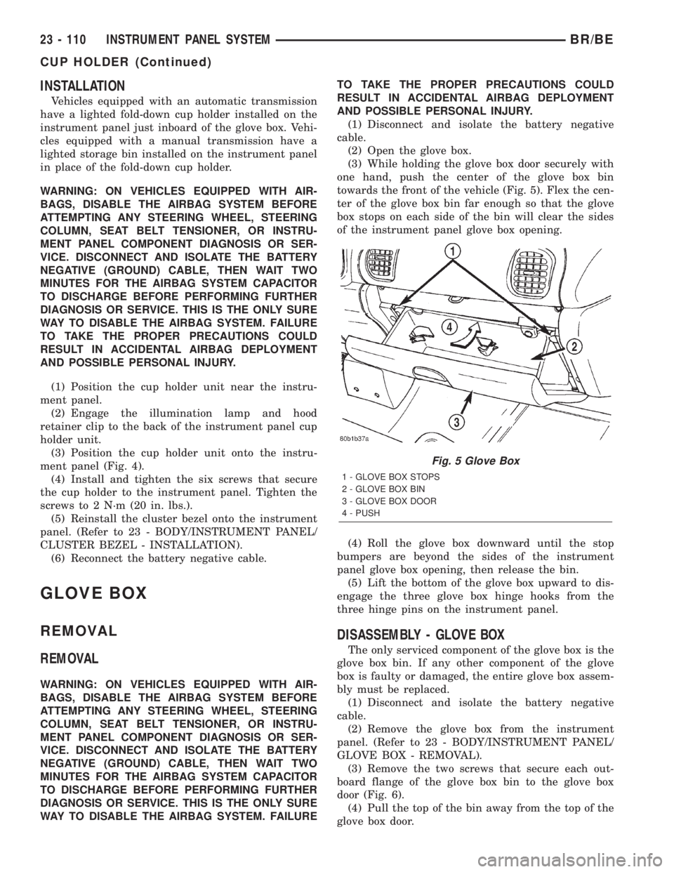
(4) Remove the six screws that secure the cup
holder to the instrument panel (Fig. 4).
(5) Pull the cup holder away from the instrument
panel far enough to access the illumination lamp and
hood unit.
(6) Disengage the illumination lamp and hood
retainer clip from the back of the instrument panel
cup holder unit.
(7) Remove the cup holder unit from the instru-
ment panel.
Fig. 3 Instrument Panel Cubby Bin Remove/Install
1 - SCREW (3)
2 - CUBBY BIN
Fig. 4 Instrument Panel Cup Holder
1 - SCREW
2 - INSTRUMENT PANEL
3 - CUP HOLDER
BR/BEINSTRUMENT PANEL SYSTEM 23 - 109
CUBBY BIN (Continued)
Page 2077 of 2255
INSTALLATION
Vehicles equipped with an automatic transmission
have a lighted fold-down cup holder installed on the
instrument panel just inboard of the glove box. Vehi-
cles equipped with a manual transmission have a
lighted storage bin installed on the instrument panel
in place of the fold-down cup holder.
WARNING: ON VEHICLES EQUIPPED WITH AIR-
BAGS, DISABLE THE AIRBAG SYSTEM BEFORE
ATTEMPTING ANY STEERING WHEEL, STEERING
COLUMN, SEAT BELT TENSIONER, OR INSTRU-
MENT PANEL COMPONENT DIAGNOSIS OR SER-
VICE. DISCONNECT AND ISOLATE THE BATTERY
NEGATIVE (GROUND) CABLE, THEN WAIT TWO
MINUTES FOR THE AIRBAG SYSTEM CAPACITOR
TO DISCHARGE BEFORE PERFORMING FURTHER
DIAGNOSIS OR SERVICE. THIS IS THE ONLY SURE
WAY TO DISABLE THE AIRBAG SYSTEM. FAILURE
TO TAKE THE PROPER PRECAUTIONS COULD
RESULT IN ACCIDENTAL AIRBAG DEPLOYMENT
AND POSSIBLE PERSONAL INJURY.
(1) Position the cup holder unit near the instru-
ment panel.
(2) Engage the illumination lamp and hood
retainer clip to the back of the instrument panel cup
holder unit.
(3) Position the cup holder unit onto the instru-
ment panel (Fig. 4).
(4) Install and tighten the six screws that secure
the cup holder to the instrument panel. Tighten the
screws to 2 N´m (20 in. lbs.).
(5) Reinstall the cluster bezel onto the instrument
panel. (Refer to 23 - BODY/INSTRUMENT PANEL/
CLUSTER BEZEL - INSTALLATION).
(6) Reconnect the battery negative cable.
GLOVE BOX
REMOVAL
REMOVAL
WARNING: ON VEHICLES EQUIPPED WITH AIR-
BAGS, DISABLE THE AIRBAG SYSTEM BEFORE
ATTEMPTING ANY STEERING WHEEL, STEERING
COLUMN, SEAT BELT TENSIONER, OR INSTRU-
MENT PANEL COMPONENT DIAGNOSIS OR SER-
VICE. DISCONNECT AND ISOLATE THE BATTERY
NEGATIVE (GROUND) CABLE, THEN WAIT TWO
MINUTES FOR THE AIRBAG SYSTEM CAPACITOR
TO DISCHARGE BEFORE PERFORMING FURTHER
DIAGNOSIS OR SERVICE. THIS IS THE ONLY SURE
WAY TO DISABLE THE AIRBAG SYSTEM. FAILURETO TAKE THE PROPER PRECAUTIONS COULD
RESULT IN ACCIDENTAL AIRBAG DEPLOYMENT
AND POSSIBLE PERSONAL INJURY.
(1) Disconnect and isolate the battery negative
cable.
(2) Open the glove box.
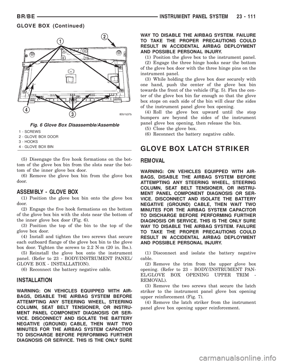
(3) While holding the glove box door securely with
one hand, push the center of the glove box bin
towards the front of the vehicle (Fig. 5). Flex the cen-
ter of the glove box bin far enough so that the glove
box stops on each side of the bin will clear the sides
of the instrument panel glove box opening.
(4) Roll the glove box downward until the stop
bumpers are beyond the sides of the instrument
panel glove box opening, then release the bin.
(5) Lift the bottom of the glove box upward to dis-
engage the three glove box hinge hooks from the
three hinge pins on the instrument panel.
DISASSEMBLY - GLOVE BOX
The only serviced component of the glove box is the
glove box bin. If any other component of the glove
box is faulty or damaged, the entire glove box assem-
bly must be replaced.
(1) Disconnect and isolate the battery negative
cable.
(2) Remove the glove box from the instrument
panel. (Refer to 23 - BODY/INSTRUMENT PANEL/
GLOVE BOX - REMOVAL).
(3) Remove the two screws that secure each out-
board flange of the glove box bin to the glove box
door (Fig. 6).
(4) Pull the top of the bin away from the top of the
glove box door.
Fig. 5 Glove Box
1 - GLOVE BOX STOPS
2 - GLOVE BOX BIN
3 - GLOVE BOX DOOR
4 - PUSH
23 - 110 INSTRUMENT PANEL SYSTEMBR/BE
CUP HOLDER (Continued)
Page 2078 of 2255
(5) Disengage the five hook formations on the bot-
tom of the glove box bin from the slots near the bot-
tom of the inner glove box door.
(6) Remove the glove box bin from the glove box
door.
ASSEMBLY - GLOVE BOX
(1) Position the glove box bin onto the glove box
door.
(2) Engage the five hook formations on the bottom
of the glove box bin with the slots near the bottom of
the inner glove box door (Fig. 6).
(3) Position the top of the bin to the top of the
glove box door.
(4) Install and tighten the two screws that secure
each outboard flange of the glove box bin to the glove
box door. Tighten the screws to 2.2 N´m (20 in. lbs.).
(5) Reinstall the glove box onto the instrument
panel. (Refer to 23 - BODY/INSTRUMENT PANEL/
GLOVE BOX - INSTALLATION).
(6) Reconnect the battery negative cable.
INSTALLATION
WARNING: ON VEHICLES EQUIPPED WITH AIR-
BAGS, DISABLE THE AIRBAG SYSTEM BEFORE
ATTEMPTING ANY STEERING WHEEL, STEERING
COLUMN, SEAT BELT TENSIONER, OR INSTRU-
MENT PANEL COMPONENT DIAGNOSIS OR SER-
VICE. DISCONNECT AND ISOLATE THE BATTERY
NEGATIVE (GROUND) CABLE, THEN WAIT TWO
MINUTES FOR THE AIRBAG SYSTEM CAPACITOR
TO DISCHARGE BEFORE PERFORMING FURTHER
DIAGNOSIS OR SERVICE. THIS IS THE ONLY SUREWAY TO DISABLE THE AIRBAG SYSTEM. FAILURE
TO TAKE THE PROPER PRECAUTIONS COULD
RESULT IN ACCIDENTAL AIRBAG DEPLOYMENT
AND POSSIBLE PERSONAL INJURY.
(1) Position the glove box to the instrument panel.
(2) Engage the three hinge hooks near the bottom
of the glove box door with the three hinge pins on the
instrument panel.
(3) While holding the glove box door securely with
one hand, push the center of the glove box bin
towards the front of the vehicle (Fig. 5). Flex the cen-
ter of the glove box bin far enough so that the glove
box stops on each side of the bin will clear the sides
of the instrument panel glove box opening.
(4) Roll the glove box upward until the stop
bumpers are beyond the sides of the instrument
panel glove box opening, then release the bin.
(5) Close the glove box.
(6) Reconnect the battery negative cable.
GLOVE BOX LATCH STRIKER
REMOVAL
WARNING: ON VEHICLES EQUIPPED WITH AIR-
BAGS, DISABLE THE AIRBAG SYSTEM BEFORE
ATTEMPTING ANY STEERING WHEEL, STEERING
COLUMN, SEAT BELT TENSIONER, OR INSTRU-
MENT PANEL COMPONENT DIAGNOSIS OR SER-
VICE. DISCONNECT AND ISOLATE THE BATTERY
NEGATIVE (GROUND) CABLE, THEN WAIT TWO
MINUTES FOR THE AIRBAG SYSTEM CAPACITOR
TO DISCHARGE BEFORE PERFORMING FURTHER
DIAGNOSIS OR SERVICE. THIS IS THE ONLY SURE
WAY TO DISABLE THE AIRBAG SYSTEM. FAILURE
TO TAKE THE PROPER PRECAUTIONS COULD
RESULT IN ACCIDENTAL AIRBAG DEPLOYMENT
AND POSSIBLE PERSONAL INJURY.
(1) Disconnect and isolate the battery negative
cable.
(2) Remove the trim from the upper glove box
opening. (Refer to 23 - BODY/INSTRUMENT PAN-
EL/GLOVE BOX OPENING UPPER TRIM -
REMOVAL).
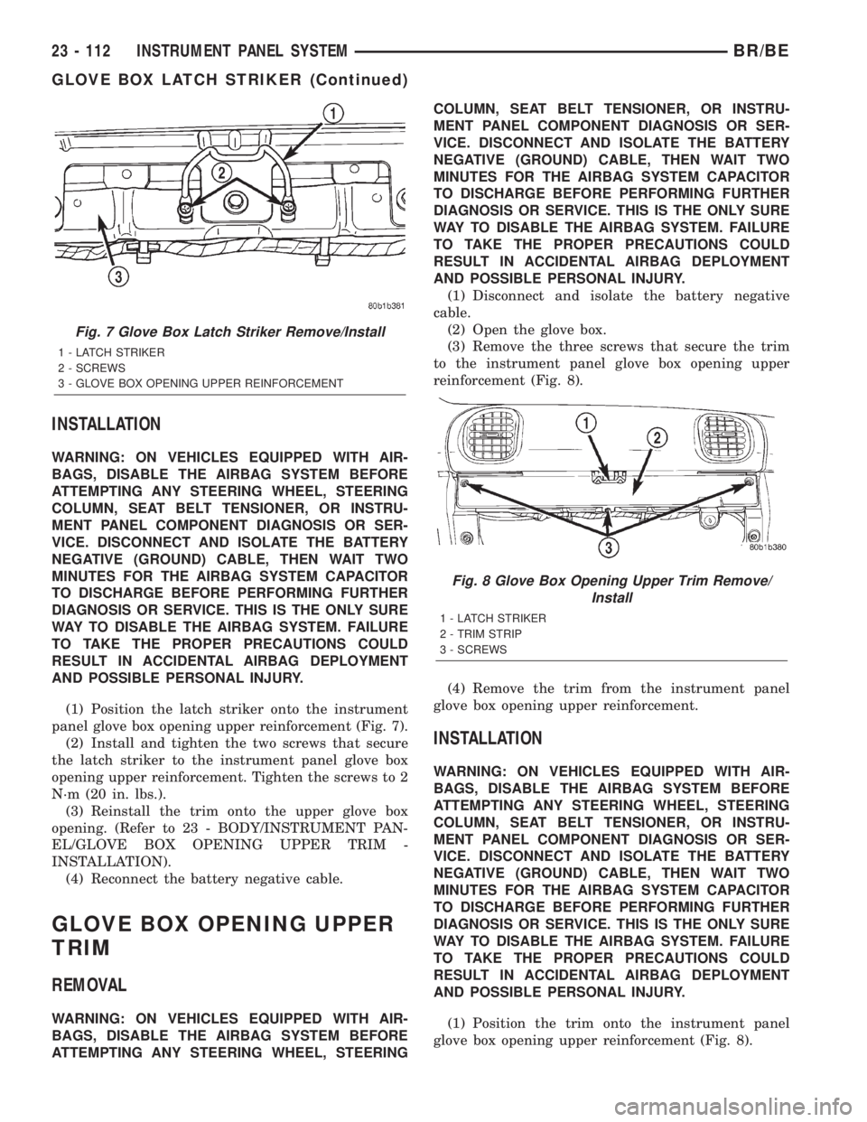
(3) Remove the two screws that secure the latch
striker to the instrument panel glove box opening
upper reinforcement (Fig. 7).
(4) Remove the latch striker from the instrument
panel glove box opening upper reinforcement.
Fig. 6 Glove Box Disassemble/Assemble
1 - SCREWS
2 - GLOVE BOX DOOR
3 - HOOKS
4 - GLOVE BOX BIN
BR/BEINSTRUMENT PANEL SYSTEM 23 - 111
GLOVE BOX (Continued)
Page 2079 of 2255
INSTALLATION
WARNING: ON VEHICLES EQUIPPED WITH AIR-
BAGS, DISABLE THE AIRBAG SYSTEM BEFORE
ATTEMPTING ANY STEERING WHEEL, STEERING
COLUMN, SEAT BELT TENSIONER, OR INSTRU-
MENT PANEL COMPONENT DIAGNOSIS OR SER-
VICE. DISCONNECT AND ISOLATE THE BATTERY
NEGATIVE (GROUND) CABLE, THEN WAIT TWO
MINUTES FOR THE AIRBAG SYSTEM CAPACITOR
TO DISCHARGE BEFORE PERFORMING FURTHER
DIAGNOSIS OR SERVICE. THIS IS THE ONLY SURE
WAY TO DISABLE THE AIRBAG SYSTEM. FAILURE
TO TAKE THE PROPER PRECAUTIONS COULD
RESULT IN ACCIDENTAL AIRBAG DEPLOYMENT
AND POSSIBLE PERSONAL INJURY.
(1) Position the latch striker onto the instrument
panel glove box opening upper reinforcement (Fig. 7).
(2) Install and tighten the two screws that secure
the latch striker to the instrument panel glove box
opening upper reinforcement. Tighten the screws to 2
N´m (20 in. lbs.).
(3) Reinstall the trim onto the upper glove box
opening. (Refer to 23 - BODY/INSTRUMENT PAN-
EL/GLOVE BOX OPENING UPPER TRIM -
INSTALLATION).
(4) Reconnect the battery negative cable.
GLOVE BOX OPENING UPPER
TRIM
REMOVAL
WARNING: ON VEHICLES EQUIPPED WITH AIR-
BAGS, DISABLE THE AIRBAG SYSTEM BEFORE
ATTEMPTING ANY STEERING WHEEL, STEERINGCOLUMN, SEAT BELT TENSIONER, OR INSTRU-
MENT PANEL COMPONENT DIAGNOSIS OR SER-
VICE. DISCONNECT AND ISOLATE THE BATTERY
NEGATIVE (GROUND) CABLE, THEN WAIT TWO
MINUTES FOR THE AIRBAG SYSTEM CAPACITOR
TO DISCHARGE BEFORE PERFORMING FURTHER
DIAGNOSIS OR SERVICE. THIS IS THE ONLY SURE
WAY TO DISABLE THE AIRBAG SYSTEM. FAILURE
TO TAKE THE PROPER PRECAUTIONS COULD
RESULT IN ACCIDENTAL AIRBAG DEPLOYMENT
AND POSSIBLE PERSONAL INJURY.
(1) Disconnect and isolate the battery negative
cable.
(2) Open the glove box.
(3) Remove the three screws that secure the trim
to the instrument panel glove box opening upper
reinforcement (Fig. 8).
(4) Remove the trim from the instrument panel
glove box opening upper reinforcement.
INSTALLATION
WARNING: ON VEHICLES EQUIPPED WITH AIR-
BAGS, DISABLE THE AIRBAG SYSTEM BEFORE
ATTEMPTING ANY STEERING WHEEL, STEERING
COLUMN, SEAT BELT TENSIONER, OR INSTRU-
MENT PANEL COMPONENT DIAGNOSIS OR SER-
VICE. DISCONNECT AND ISOLATE THE BATTERY
NEGATIVE (GROUND) CABLE, THEN WAIT TWO
MINUTES FOR THE AIRBAG SYSTEM CAPACITOR
TO DISCHARGE BEFORE PERFORMING FURTHER
DIAGNOSIS OR SERVICE. THIS IS THE ONLY SURE
WAY TO DISABLE THE AIRBAG SYSTEM. FAILURE
TO TAKE THE PROPER PRECAUTIONS COULD
RESULT IN ACCIDENTAL AIRBAG DEPLOYMENT
AND POSSIBLE PERSONAL INJURY.
(1) Position the trim onto the instrument panel
glove box opening upper reinforcement (Fig. 8).
Fig. 7 Glove Box Latch Striker Remove/Install
1 - LATCH STRIKER
2 - SCREWS
3 - GLOVE BOX OPENING UPPER REINFORCEMENT
Fig. 8 Glove Box Opening Upper Trim Remove/
Install
1 - LATCH STRIKER
2 - TRIM STRIP
3 - SCREWS
23 - 112 INSTRUMENT PANEL SYSTEMBR/BE
GLOVE BOX LATCH STRIKER (Continued)