2002 DODGE RAM spark plugs replace
[x] Cancel search: spark plugs replacePage 349 of 2255

RADIO NOISE SUPPRESSION
COMPONENTS
DESCRIPTION
Radio Frequency Interference (RFI) and Electro-
Magnetic Interference (EMI) noise suppression is
accomplished primarily through circuitry internal to
the radio receivers. These internal suppression
devices are only serviced as part of the radio receiver.
External suppression devices that are used on this
vehicle to control RFI or EMI noise include the fol-
lowing:
²Radio antenna base ground
²Radio receiver chassis ground wire or strap
²Engine-to-body ground straps
²Cab-to-bed ground strap
²Heater core ground strap
²Resistor-type spark plugs
²Radio suppression-type secondary ignition wir-
ing.
For more information on the spark plugs and sec-
ondary ignition components, refer to Electrical, Igni-
tion Control.
DIAGNOSIS AND TESTING - RADIO NOISE
SUPPRESSION COMPONENTS
WARNING: ON VEHICLES EQUIPPED WITH AIR-
BAGS, REFER TO ELECTRICAL, RESTRAINTS
BEFORE ATTEMPTING ANY STEERING WHEEL,
STEERING COLUMN, OR INSTRUMENT PANEL
COMPONENT DIAGNOSIS OR SERVICE. FAILURE
TO TAKE THE PROPER PRECAUTIONS COULD
RESULT IN ACCIDENTAL AIRBAG DEPLOYMENT
AND POSSIBLE PERSONAL INJURY.
For complete circuit diagrams, refer to the appro-
priate wiring information. The wiring information
includes wiring diagrams, proper wire and connector
repair procedures, details of wire harness routing
and retention, connector pin-out information and
location views for the various wire harness connec-
tors, splices and grounds. Inspect the ground paths
and connections at the following locations:
²Blower motor
²Cab-to-bed ground strap
²Electric fuel pump
²Engine-to-body ground straps
²Generator
²Ignition module
²Heater core ground strap
²Radio antenna base ground
²Radio receiver chassis ground wire or strap
²Wiper motor.If the source of RFI or EMI noise is identified as a
component on the vehicle (i.e., generator, blower
motor, etc.), the ground path for that component
should be checked. If excessive resistance is found in
any ground circuit, clean, tighten, or repair the
ground circuits or connections to ground as required
before considering any component replacement.
For service and inspection of secondary ignition
components, refer to Electrical, Ignition Control.
Inspect the following secondary ignition system com-
ponents:
²Distributor cap and rotor
²Ignition coil
²Spark plugs
²Spark plug wire routing and condition.
Reroute the spark plug wires or replace the faulty
components as required.
If the source of the RFI or EMI noise is identified
as two-way mobile radio or telephone equipment,
check the equipment installation for the following:
²Power connections should be made directly to
the battery, and fused as closely to the battery as
possible.
²The antenna should be mounted on the roof or
toward the rear of the vehicle. Remember that mag-
netic antenna mounts on the roof panel can adversely
affect the operation of an overhead console compass,
if the vehicle is so equipped.
²The antenna cable should be fully shielded coax-
ial cable, should be as short as is practical, and
should be routed away from the factory-installed
vehicle wire harnesses whenever possible.
²The antenna and cable must be carefully
matched to ensure a low Standing Wave Ratio
(SWR).
Fleet vehicles are available with an extra-cost RFI-
suppressed Powertrain Control Module (PCM). This
unit reduces interference generated by the PCM on
some radio frequencies used in two-way radio com-
munications. However, this unit will not resolve com-
plaints of RFI in the commercial AM or FM radio
frequency ranges.
ENGINE-TO-BODY GROUND
STRAP
REMOVAL
(1) Remove the screw that secures the engine-to-
body ground strap eyelet to the dash panel (Fig. 10).
(2) Remove the screw that secures the engine-to-
body ground strap eyelet to the back of the engine
cylinder head (Fig. 11) or (Fig. 12).
8A - 12 AUDIOBR/BE
Page 473 of 2255
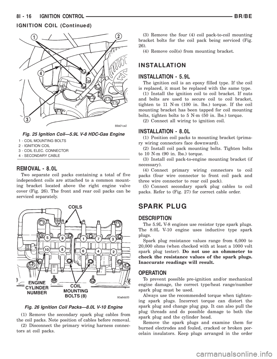
REMOVAL - 8.0L
Two separate coil packs containing a total of five
independent coils are attached to a common mount-
ing bracket located above the right engine valve
cover (Fig. 26). The front and rear coil packs can be
serviced separately.
(1) Remove the secondary spark plug cables from
the coil packs. Note position of cables before removal.
(2) Disconnect the primary wiring harness connec-
tors at coil packs.(3) Remove the four (4) coil pack-to-coil mounting
bracket bolts for the coil pack being serviced (Fig.
26).
(4) Remove coil(s) from mounting bracket.
INSTALLATION
INSTALLATION - 5.9L
The ignition coil is an epoxy filled type. If the coil
is replaced, it must be replaced with the same type.
(1) Install the ignition coil to coil bracket. If nuts
and bolts are used to secure coil to coil bracket,
tighten to 11 N´m (100 in. lbs.) torque. If the coil
mounting bracket has been tapped for coil mounting
bolts, tighten bolts to 5 N´m (50 in. lbs.) torque.
(2) Connect all wiring to ignition coil.
INSTALLATION - 8.0L
(1) Position coil packs to mounting bracket (prima-
ry wiring connectors face downward).
(2) Install coil pack mounting bolts. Tighten bolts
to 10 N´m (90 in. lbs.) torque.
(3) Install coil pack-to-engine mounting bracket (if
necessary).
(4) Connect primary wiring connectors to coil
packs (four wire connector to front coil pack and
three wire connector to rear coil pack).
(5) Connect secondary spark plug cables to coil
packs. Refer to (Fig. 27) for correct cable order.
SPARK PLUG
DESCRIPTION
The 5.9L V-8 engines use resistor type spark plugs.
The 8.0L V-10 engine uses inductive type spark
plugs.
Spark plug resistance values range from 6,000 to
20,000 ohms (when checked with at least a 1000 volt
spark plug tester).Do not use an ohmmeter to
check the resistance values of the spark plugs.
Inaccurate readings will result.
OPERATION
To prevent possible pre-ignition and/or mechanical
engine damage, the correct type/heat range/number
spark plug must be used.
Always use the recommended torque when tighten-
ing spark plugs. Incorrect torque can distort the
spark plug and change plug gap. It can also pull the
plug threads and do possible damage to both the
spark plug and the cylinder head.
Remove the spark plugs and examine them for
burned electrodes and fouled, cracked or broken por-
celain insulators. Keep plugs arranged in the order
Fig. 25 Ignition CoilÐ5.9L V-8 HDC-Gas Engine
1 - COIL MOUNTING BOLTS
2 - IGNITION COIL
3 - COIL ELEC. CONNECTOR
4 - SECONDARY CABLE
Fig. 26 Ignition Coil PacksÐ8.0L V-10 Engine
8I - 16 IGNITION CONTROLBR/BE
IGNITION COIL (Continued)
Page 474 of 2255

in which they were removed from the engine. A sin-
gle plug displaying an abnormal condition indicates
that a problem exists in the corresponding cylinder.
Replace spark plugs at the intervals recommended in
Group O, Lubrication and Maintenance
Spark plugs that have low mileage may be cleaned
and reused if not otherwise defective, carbon or oil
fouled. Also refer to Spark Plug Conditions.
CAUTION: Never use a motorized wire wheel brush
to clean the spark plugs. Metallic deposits will
remain on the spark plug insulator and will cause
plug misfire.
DIAGNOSIS AND TESTING - SPARK PLUG
CONDITIONS
NORMAL OPERATING
The few deposits present on the spark plug will
probably be light tan or slightly gray in color. This is
evident with most grades of commercial gasoline
(Fig. 28). There will not be evidence of electrode
burning. Gap growth will not average more than
approximately 0.025 mm (.001 in) per 3200 km (2000
miles) of operation. Spark plugs that have normalwear can usually be cleaned, have the electrodes
filed, have the gap set and then be installed.
Some fuel refiners in several areas of the United
States have introduced a manganese additive (MMT)
for unleaded fuel. During combustion, fuel with MMT
causes the entire tip of the spark plug to be coated
with a rust colored deposit. This rust color can be
misdiagnosed as being caused by coolant in the com-
bustion chamber. Spark plug performance may be
affected by MMT deposits.
COLD FOULING/CARBON FOULING
Cold fouling is sometimes referred to as carbon
fouling. The deposits that cause cold fouling are basi-
cally carbon (Fig. 28). A dry, black deposit on one or
two plugs in a set may be caused by sticking valves
or defective spark plug cables. Cold (carbon) fouling
of the entire set of spark plugs may be caused by a
clogged air cleaner element or repeated short operat-
ing times (short trips).
WET FOULING OR GAS FOULING
A spark plug coated with excessive wet fuel or oil
is wet fouled. In older engines, worn piston rings,
leaking valve guide seals or excessive cylinder wear
can cause wet fouling. In new or recently overhauled
engines, wet fouling may occur before break-in (nor-
mal oil control) is achieved. This condition can usu-
ally be resolved by cleaning and reinstalling the
fouled plugs.
OIL OR ASH ENCRUSTED
If one or more spark plugs are oil or oil ash
encrusted (Fig. 29), evaluate engine condition for the
Fig. 27 Spark Plug Cable OrderÐ8.0L V-10 Engine
Fig. 28 Normal Operation and Cold (Carbon) Fouling
1 - NORMAL
2 - DRY BLACK DEPOSITS
3 - COLD (CARBON) FOULING
BR/BEIGNITION CONTROL 8I - 17
SPARK PLUG (Continued)
Page 475 of 2255
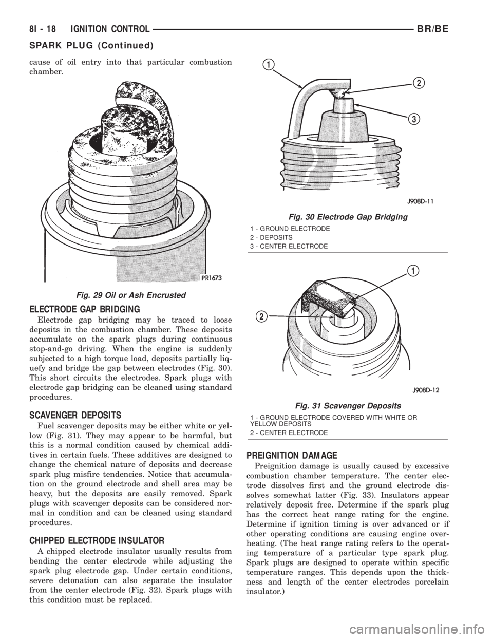
cause of oil entry into that particular combustion
chamber.
ELECTRODE GAP BRIDGING
Electrode gap bridging may be traced to loose
deposits in the combustion chamber. These deposits
accumulate on the spark plugs during continuous
stop-and-go driving. When the engine is suddenly
subjected to a high torque load, deposits partially liq-
uefy and bridge the gap between electrodes (Fig. 30).
This short circuits the electrodes. Spark plugs with
electrode gap bridging can be cleaned using standard
procedures.
SCAVENGER DEPOSITS
Fuel scavenger deposits may be either white or yel-
low (Fig. 31). They may appear to be harmful, but
this is a normal condition caused by chemical addi-
tives in certain fuels. These additives are designed to
change the chemical nature of deposits and decrease
spark plug misfire tendencies. Notice that accumula-
tion on the ground electrode and shell area may be
heavy, but the deposits are easily removed. Spark
plugs with scavenger deposits can be considered nor-
mal in condition and can be cleaned using standard
procedures.
CHIPPED ELECTRODE INSULATOR
A chipped electrode insulator usually results from
bending the center electrode while adjusting the
spark plug electrode gap. Under certain conditions,
severe detonation can also separate the insulator
from the center electrode (Fig. 32). Spark plugs with
this condition must be replaced.
PREIGNITION DAMAGE
Preignition damage is usually caused by excessive
combustion chamber temperature. The center elec-
trode dissolves first and the ground electrode dis-
solves somewhat latter (Fig. 33). Insulators appear
relatively deposit free. Determine if the spark plug
has the correct heat range rating for the engine.
Determine if ignition timing is over advanced or if
other operating conditions are causing engine over-
heating. (The heat range rating refers to the operat-
ing temperature of a particular type spark plug.
Spark plugs are designed to operate within specific
temperature ranges. This depends upon the thick-
ness and length of the center electrodes porcelain
insulator.)
Fig. 29 Oil or Ash Encrusted
Fig. 30 Electrode Gap Bridging
1 - GROUND ELECTRODE
2 - DEPOSITS
3 - CENTER ELECTRODE
Fig. 31 Scavenger Deposits
1 - GROUND ELECTRODE COVERED WITH WHITE OR
YELLOW DEPOSITS
2 - CENTER ELECTRODE
8I - 18 IGNITION CONTROLBR/BE
SPARK PLUG (Continued)
Page 477 of 2255

(2) Prior to removing the spark plug, spray com-
pressed air around the spark plug hole and the area
around the spark plug. This will help prevent foreign
material from entering the combustion chamber.
(3) Remove the spark plug using a quality socket
with a rubber or foam insert.
(4) Inspect the spark plug condition. Refer to
Spark Plug Condition in the Diagnostics and Testing
section of this group.
CLEANING
The plugs may be cleaned using commercially
available spark plug cleaning equipment. After clean-
ing, file center electrode flat with a small point file or
jewelers file before adjusting gap.
CAUTION: Never use a motorized wire wheel brush
to clean spark plugs. Metallic deposits will remain
on spark plug insulator and will cause plug misfire.
INSTALLATION
Special care should be taken when installing spark
plugs into the cylinder head spark plug wells. Be
sure the plugs do not drop into the plug wells as elec-
trodes can be damaged.
Always tighten spark plugs to the specified torque.
Over tightening can cause distortion resulting in a
change in the spark plug gap or a cracked porcelain
insulator.
When replacing the spark plug and ignition coil
cables, route the cables correctly and secure them in
the appropriate retainers. Failure to route the cables
properly can cause the radio to reproduce ignition
noise. It could cause cross ignition of the spark plugs
or short circuit the cables to ground.
(1) Start the spark plug into the cylinder head by
hand to avoid cross threading.
(2) Tighten spark plugs to 35-41 N´m (26-30 ft.
lbs.) torque.
(3) Install spark plug cables over spark plugs.
SPARK PLUG CABLE
DESCRIPTION
Spark plug cables are sometimes referred to as sec-
ondary ignition wires.
OPERATION
The spark plug cables transfer electrical current
from the ignition coil(s) and/or distributor, to individ-
ual spark plugs at each cylinder. The resistive spark
plug cables are of nonmetallic construction. The
cables provide suppression of radio frequency emis-
sions from the ignition system.
DIAGNOSIS AND TESTING - SPARK PLUG
CABLES
Cable routing is important on certain engines. To
prevent possible ignition crossfire, be sure the cables
are clipped into the plastic routing looms. Try to pre-
vent any one cable from contacting another. Before
removing cables, note their original location and
routing. Never allow one cable to be twisted around
another.
Check the spark plug cable connections for good
contact at the coil(s), distributor cap towers, and
spark plugs. Terminals should be fully seated. The
insulators should be in good condition and should fit
tightly on the coil, distributor and spark plugs. Spark
plug cables with insulators that are cracked or torn
must be replaced.
Clean high voltage ignition cables with a cloth
moistened with a non-flammable solvent. Wipe the
cables dry. Check for brittle or cracked insulation.
On 5.9L engines, spark plug cable heat shields are
pressed into the cylinder head to surround each
spark plug cable boot and spark plug (Fig. 36). These
shields protect the spark plug boots from damage
(due to intense engine heat generated by the exhaust
manifolds) and should not be removed. After the
spark plug cable has been installed, the lip of the
cable boot should have a small air gap to the top of
the heat shield (Fig. 36).
TESTING
When testing secondary cables for damage with an
oscilloscope, follow the instructions of the equipment
manufacturer.
If an oscilloscope is not available, spark plug cables
may be tested as follows:
Fig. 36 Heat ShieldsÐ5.9L Engines
1 - AIR GAP
2 - SPARK PLUG BOOT HEAT SHIELD
8I - 20 IGNITION CONTROLBR/BE
SPARK PLUG (Continued)
Page 1079 of 2255
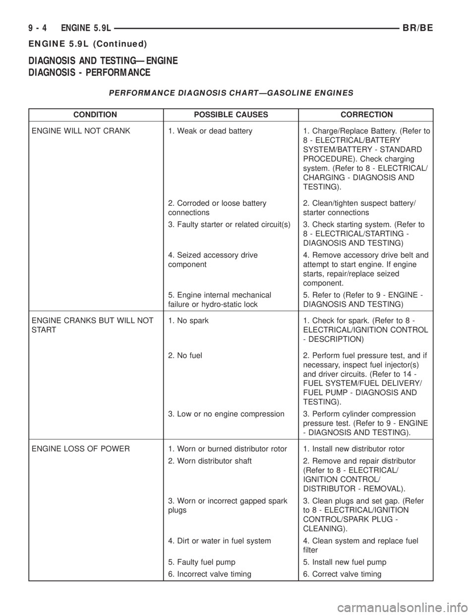
DIAGNOSIS AND TESTINGÐENGINE
DIAGNOSIS - PERFORMANCE
PERFORMANCE DIAGNOSIS CHARTÐGASOLINE ENGINES
CONDITION POSSIBLE CAUSES CORRECTION
ENGINE WILL NOT CRANK 1. Weak or dead battery 1. Charge/Replace Battery. (Refer to
8 - ELECTRICAL/BATTERY
SYSTEM/BATTERY - STANDARD
PROCEDURE). Check charging
system. (Refer to 8 - ELECTRICAL/
CHARGING - DIAGNOSIS AND
TESTING).
2. Corroded or loose battery
connections2. Clean/tighten suspect battery/
starter connections
3. Faulty starter or related circuit(s) 3. Check starting system. (Refer to
8 - ELECTRICAL/STARTING -
DIAGNOSIS AND TESTING)
4. Seized accessory drive
component4. Remove accessory drive belt and
attempt to start engine. If engine
starts, repair/replace seized
component.
5. Engine internal mechanical
failure or hydro-static lock5. Refer to (Refer to 9 - ENGINE -
DIAGNOSIS AND TESTING)
ENGINE CRANKS BUT WILL NOT
START1. No spark 1. Check for spark. (Refer to 8 -
ELECTRICAL/IGNITION CONTROL
- DESCRIPTION)
2. No fuel 2. Perform fuel pressure test, and if
necessary, inspect fuel injector(s)
and driver circuits. (Refer to 14 -
FUEL SYSTEM/FUEL DELIVERY/
FUEL PUMP - DIAGNOSIS AND
TESTING).
3. Low or no engine compression 3. Perform cylinder compression
pressure test. (Refer to 9 - ENGINE
- DIAGNOSIS AND TESTING).
ENGINE LOSS OF POWER 1. Worn or burned distributor rotor 1. Install new distributor rotor
2. Worn distributor shaft 2. Remove and repair distributor
(Refer to 8 - ELECTRICAL/
IGNITION CONTROL/
DISTRIBUTOR - REMOVAL).
3. Worn or incorrect gapped spark
plugs3. Clean plugs and set gap. (Refer
to 8 - ELECTRICAL/IGNITION
CONTROL/SPARK PLUG -
CLEANING).
4. Dirt or water in fuel system 4. Clean system and replace fuel
filter
5. Faulty fuel pump 5. Install new fuel pump
6. Incorrect valve timing 6. Correct valve timing
9 - 4 ENGINE 5.9LBR/BE
ENGINE 5.9L (Continued)
Page 1080 of 2255
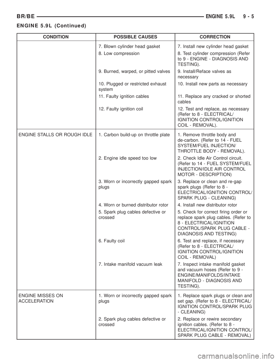
CONDITION POSSIBLE CAUSES CORRECTION
7. Blown cylinder head gasket 7. Install new cylinder head gasket
8. Low compression 8. Test cylinder compression (Refer
to 9 - ENGINE - DIAGNOSIS AND
TESTING).
9. Burned, warped, or pitted valves 9. Install/Reface valves as
necessary
10. Plugged or restricted exhaust
system10. Install new parts as necessary
11. Faulty ignition cables 11. Replace any cracked or shorted
cables
12. Faulty ignition coil 12. Test and replace, as necessary
(Refer to 8 - ELECTRICAL/
IGNITION CONTROL/IGNITION
COIL - REMOVAL).
ENGINE STALLS OR ROUGH IDLE 1. Carbon build-up on throttle plate 1. Remove throttle body and
de-carbon. (Refer to 14 - FUEL
SYSTEM/FUEL INJECTION/
THROTTLE BODY - REMOVAL).
2. Engine idle speed too low 2. Check Idle Air Control circuit.
(Refer to 14 - FUEL SYSTEM/FUEL
INJECTION/IDLE AIR CONTROL
MOTOR - DESCRIPTION)
3. Worn or incorrectly gapped spark
plugs3. Replace or clean and re-gap
spark plugs (Refer to 8 -
ELECTRICAL/IGNITION CONTROL/
SPARK PLUG - CLEANING)
4. Worn or burned distributor rotor 4. Install new distributor rotor
5. Spark plug cables defective or
crossed5. Check for correct firing order or
replace spark plug cables. (Refer to
8 - ELECTRICAL/IGNITION
CONTROL/SPARK PLUG CABLE -
DIAGNOSIS AND TESTING)
6. Faulty coil 6. Test and replace, if necessary
(Refer to 8 - ELECTRICAL/
IGNITION CONTROL/IGNITION
COIL - REMOVAL)
7. Intake manifold vacuum leak 7. Inspect intake manifold gasket
and vacuum hoses (Refer to 9 -
ENGINE/MANIFOLDS/INTAKE
MANIFOLD - DIAGNOSIS AND
TESTING).
ENGINE MISSES ON
ACCELERATION1. Worn or incorrectly gapped spark
plugs1. Replace spark plugs or clean and
set gap. (Refer to 8 - ELECTRICAL/
IGNITION CONTROL/SPARK PLUG
- CLEANING)
2. Spark plug cables defective or
crossed2. Replace or rewire secondary
ignition cables. (Refer to 8 -
ELECTRICAL/IGNITION CONTROL/
SPARK PLUG CABLE - REMOVAL)
BR/BEENGINE 5.9L 9 - 5
ENGINE 5.9L (Continued)
Page 1083 of 2255
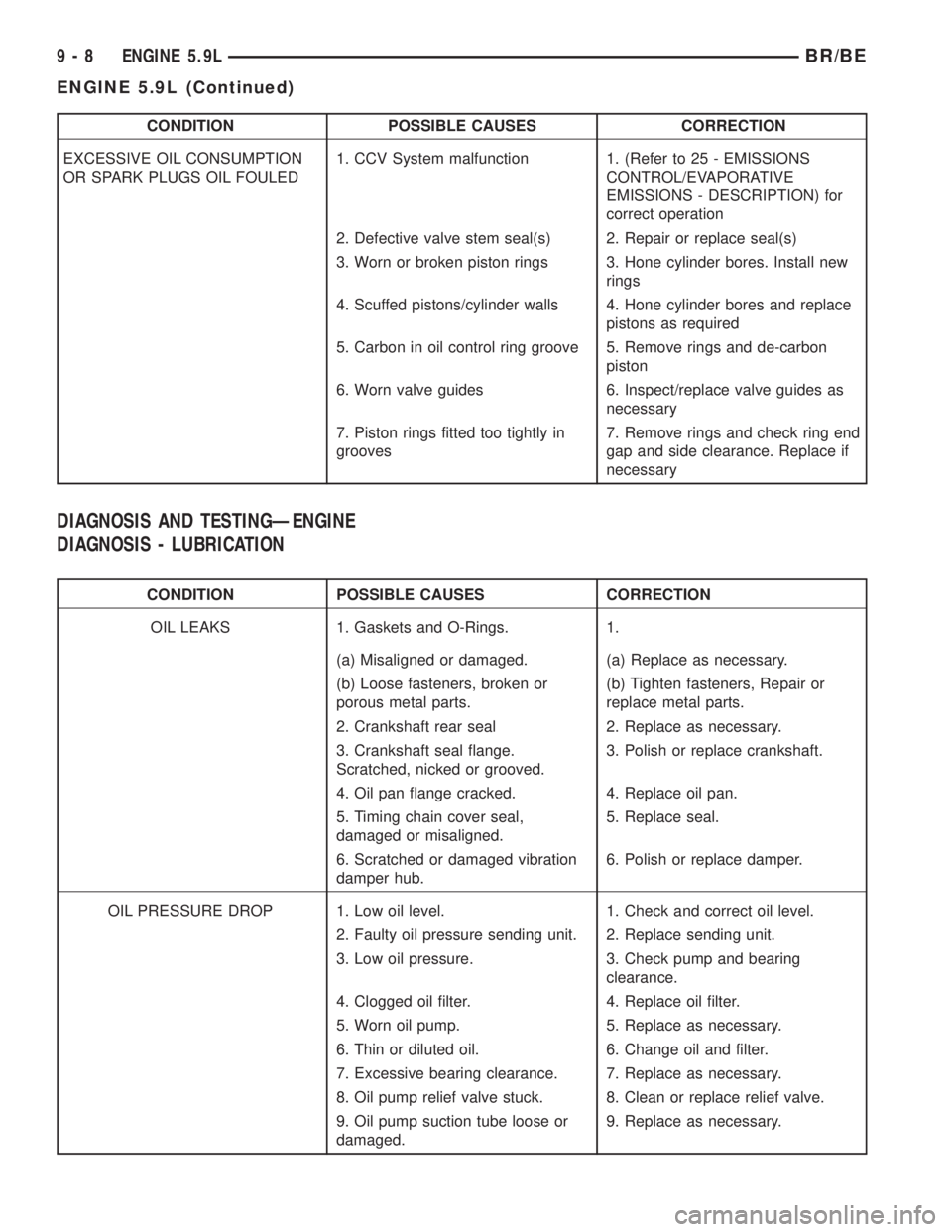
CONDITION POSSIBLE CAUSES CORRECTION
EXCESSIVE OIL CONSUMPTION
OR SPARK PLUGS OIL FOULED1. CCV System malfunction 1. (Refer to 25 - EMISSIONS
CONTROL/EVAPORATIVE
EMISSIONS - DESCRIPTION) for
correct operation
2. Defective valve stem seal(s) 2. Repair or replace seal(s)
3. Worn or broken piston rings 3. Hone cylinder bores. Install new
rings
4. Scuffed pistons/cylinder walls 4. Hone cylinder bores and replace
pistons as required
5. Carbon in oil control ring groove 5. Remove rings and de-carbon
piston
6. Worn valve guides 6. Inspect/replace valve guides as
necessary
7. Piston rings fitted too tightly in
grooves7. Remove rings and check ring end
gap and side clearance. Replace if
necessary
DIAGNOSIS AND TESTINGÐENGINE
DIAGNOSIS - LUBRICATION
CONDITION POSSIBLE CAUSES CORRECTION
OIL LEAKS 1. Gaskets and O-Rings. 1.
(a) Misaligned or damaged. (a) Replace as necessary.
(b) Loose fasteners, broken or
porous metal parts.(b) Tighten fasteners, Repair or
replace metal parts.
2. Crankshaft rear seal 2. Replace as necessary.
3. Crankshaft seal flange.
Scratched, nicked or grooved.3. Polish or replace crankshaft.
4. Oil pan flange cracked. 4. Replace oil pan.
5. Timing chain cover seal,
damaged or misaligned.5. Replace seal.
6. Scratched or damaged vibration
damper hub.6. Polish or replace damper.
OIL PRESSURE DROP 1. Low oil level. 1. Check and correct oil level.
2. Faulty oil pressure sending unit. 2. Replace sending unit.
3. Low oil pressure. 3. Check pump and bearing
clearance.
4. Clogged oil filter. 4. Replace oil filter.
5. Worn oil pump. 5. Replace as necessary.
6. Thin or diluted oil. 6. Change oil and filter.
7. Excessive bearing clearance. 7. Replace as necessary.
8. Oil pump relief valve stuck. 8. Clean or replace relief valve.
9. Oil pump suction tube loose or
damaged.9. Replace as necessary.
9 - 8 ENGINE 5.9LBR/BE
ENGINE 5.9L (Continued)