2002 DODGE RAM four wheel drive
[x] Cancel search: four wheel drivePage 24 of 2255

TOWING WHEN KEYS ARE NOT AVAILABLE
When the vehicle is locked and keys are not avail-
able, use a flat bed hauler. A Wheel-lift or Sling-type
device can be used on 4WD vehicles providedall the
wheels are lifted off the ground using tow dol-
lies.
FOUR-WHEEL-DRIVE VEHICLE TOWING
Chrysler Corporation recommends that a vehicle be
transported on a flat-bed device. A Wheel-lift or
Sling-type device can be used providedall the
wheels are lifted off the ground using tow dol-
lies.WARNING: WHEN TOWING A DISABLED VEHICLE
AND THE DRIVE WHEELS ARE SECURED IN A
WHEEL LIFT OR TOW DOLLIES, ENSURE THE
TRANSMISSION IS IN THE PARK POSITION (AUTO-
MATIC TRANSMISSION) OR A FORWARD DRIVE
GEAR (MANUAL TRANSMISSION).
CAUTION: Many vehicles are equipped with air
dams, spoilers, and/or ground effect panels. To
avoid component damage, a wheel-lift towing vehi-
cle or a flat-bed hauling vehicle is recommended.
BR/BELUBRICATION & MAINTENANCE 0 - 11
TOWING (Continued)
Page 57 of 2255

DRIVELINE VIBRATION
Drive Condition Possible Cause Correction
Propeller Shaft Noise 1) Undercoating or other foreign
material on shaft.1) Clean exterior of shaft and wash
with solvent.
2) Loose U-joint clamp screws. 2) Install new clamps and screws
and tighten to proper torque.
3) Loose or bent U-joint yoke or
excessive runout.3) Install new yoke.
4) Incorrect driveline angularity. 4) Measure and correct driveline
angles.
5) Rear spring center bolt not in
seat.5) Loosen spring u-bolts and seat
center bolt.
6) Worn U-joint bearings. 6) Install new U-joint.
7) Propeller shaft damaged or out
of balance.7) Installl new propeller shaft.
8) Broken rear spring. 8) Install new rear spring.
9) Excessive runout or unbalanced
condition.9) Re-index propeller shaft, test,
and evaluate.
10) Excessive drive pinion gear
shaft runout.10) Re-index propeller shaft and
evaluate.
11) Excessive axle yoke deflection. 11) Inspect and replace yoke if
necessary.
12) Excessive transfer case runout. 12) Inspect and repair as necessary.
Universal Joint Noise 1) Loose U-joint clamp screws. 1) Install new clamps and screws
and tighten to proper torque.
2) Lack of lubrication. 2) Replace as U-joints as
necessary.
BALANCE
NOTE: Removing and re-indexing the propeller
shaft 180É relative to the yoke may eliminate some
vibrations.
If propeller shaft is suspected of being unbalanced,
it can be verified with the following procedure:
(1) Raise the vehicle.
(2) Clean all the foreign material from the propel-
ler shaft and the universal joints.
(3) Inspect the propeller shaft for missing balance
weights, broken welds and bent areas.If the propel-
ler shaft is bent, it must be replaced.
(4) Inspect the universal joints to ensure that they
are not worn, properly installed and correctly aligned
with the shaft.
(5) Check the universal joint clamp screws torque.
(6) Remove the wheels and tires. Install the wheel
lug nuts to retain the brake drums or rotors.
(7) Mark and number the shaft six inches from the
yoke end at four positions 90É apart.(8) Run and accelerate the vehicle until vibration
occurs. Note the intensity and speed the vibration
occurred. Stop the engine.
(9) Install a screw clamp at position 1 (Fig. 1).
(10) Start the engine and re-check for vibration. If
there is little or no change in vibration, move the
clamp to one of the other three positions. Repeat the
vibration test.
(11) If there is no difference in vibration at the
other positions, the source of the vibration may not
be propeller shaft.
(12) If the vibration decreased, install a second
clamp (Fig. 2) and repeat the test.
(13) If the additional clamp causes an additional
vibration, separate the clamps (1/2 inch above and
below the mark). Repeat the vibration test (Fig. 3).
(14) Increase distance between the clamp screws
and repeat the test until the amount of vibration is
at the lowest level. Bend the slack end of the clamps
so the screws will not loosen.
3 - 2 PROPELLER SHAFTBR/BE
PROPELLER SHAFT (Continued)
Page 86 of 2255
AXLE SHAFT SEALS
REMOVAL
(1) Remove hub bearings and axle shafts.
(2) Remove axle shaft seal from the differential
housing with a long drift or punch.Be careful not
to damage housing.
(3) Clean the inside perimeter of the differential
housing with fine crocus cloth.
INSTALLATION
(1) Apply a light film of oil to the inside lip of the
new axle shaft seal.
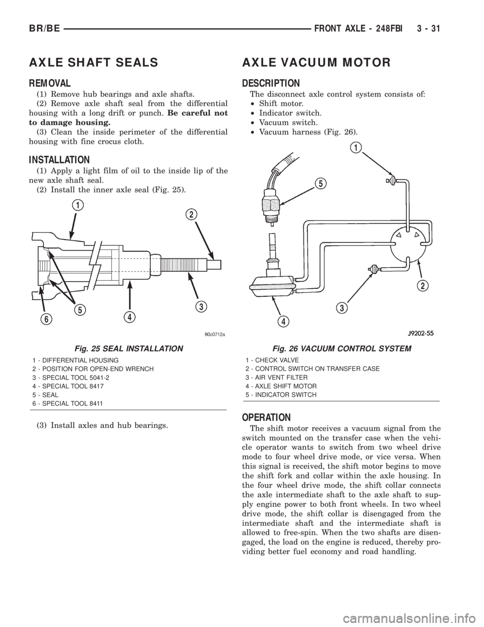
(2) Install the inner axle seal (Fig. 25).
(3) Install axles and hub bearings.
AXLE VACUUM MOTOR
DESCRIPTION
The disconnect axle control system consists of:
²Shift motor.
²Indicator switch.
²Vacuum switch.
²Vacuum harness (Fig. 26).
OPERATION
The shift motor receives a vacuum signal from the
switch mounted on the transfer case when the vehi-
cle operator wants to switch from two wheel drive
mode to four wheel drive mode, or vice versa. When
this signal is received, the shift motor begins to move
the shift fork and collar within the axle housing. In
the four wheel drive mode, the shift collar connects
the axle intermediate shaft to the axle shaft to sup-
ply engine power to both front wheels. In two wheel
drive mode, the shift collar is disengaged from the
intermediate shaft and the intermediate shaft is
allowed to free-spin. When the two shafts are disen-
gaged, the load on the engine is reduced, thereby pro-
viding better fuel economy and road handling.
Fig. 25 SEAL INSTALLATION
1 - DIFFERENTIAL HOUSING
2 - POSITION FOR OPEN-END WRENCH
3 - SPECIAL TOOL 5041-2
4 - SPECIAL TOOL 8417
5 - SEAL
6 - SPECIAL TOOL 8411
Fig. 26 VACUUM CONTROL SYSTEM
1 - CHECK VALVE
2 - CONTROL SWITCH ON TRANSFER CASE
3 - AIR VENT FILTER
4 - AXLE SHIFT MOTOR
5 - INDICATOR SWITCH
BR/BEFRONT AXLE - 248FBI 3 - 31
Page 90 of 2255
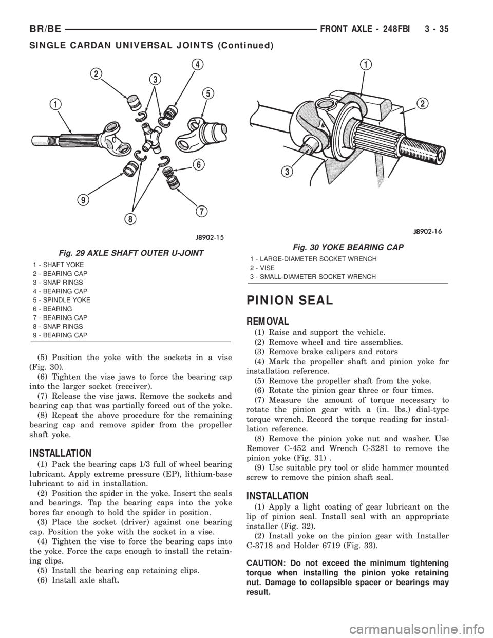
(5) Position the yoke with the sockets in a vise
(Fig. 30).
(6) Tighten the vise jaws to force the bearing cap
into the larger socket (receiver).
(7) Release the vise jaws. Remove the sockets and
bearing cap that was partially forced out of the yoke.
(8) Repeat the above procedure for the remaining
bearing cap and remove spider from the propeller
shaft yoke.
INSTALLATION
(1) Pack the bearing caps 1/3 full of wheel bearing
lubricant. Apply extreme pressure (EP), lithium-base
lubricant to aid in installation.
(2) Position the spider in the yoke. Insert the seals
and bearings. Tap the bearing caps into the yoke
bores far enough to hold the spider in position.
(3) Place the socket (driver) against one bearing
cap. Position the yoke with the socket in a vise.
(4) Tighten the vise to force the bearing caps into
the yoke. Force the caps enough to install the retain-
ing clips.
(5) Install the bearing cap retaining clips.
(6) Install axle shaft.
PINION SEAL
REMOVAL
(1) Raise and support the vehicle.
(2) Remove wheel and tire assemblies.
(3) Remove brake calipers and rotors
(4) Mark the propeller shaft and pinion yoke for
installation reference.
(5) Remove the propeller shaft from the yoke.
(6) Rotate the pinion gear three or four times.
(7) Measure the amount of torque necessary to
rotate the pinion gear with a (in. lbs.) dial-type
torque wrench. Record the torque reading for instal-
lation reference.
(8) Remove the pinion yoke nut and washer. Use
Remover C-452 and Wrench C-3281 to remove the
pinion yoke (Fig. 31) .
(9) Use suitable pry tool or slide hammer mounted
screw to remove the pinion shaft seal.
INSTALLATION
(1) Apply a light coating of gear lubricant on the
lip of pinion seal. Install seal with an appropriate
installer (Fig. 32).
(2) Install yoke on the pinion gear with Installer
C-3718 and Holder 6719 (Fig. 33).
CAUTION: Do not exceed the minimum tightening
torque when installing the pinion yoke retaining
nut. Damage to collapsible spacer or bearings may
result.
Fig. 29 AXLE SHAFT OUTER U-JOINT
1 - SHAFT YOKE
2 - BEARING CAP
3 - SNAP RINGS
4 - BEARING CAP
5 - SPINDLE YOKE
6 - BEARING
7 - BEARING CAP
8 - SNAP RINGS
9 - BEARING CAP
Fig. 30 YOKE BEARING CAP
1 - LARGE-DIAMETER SOCKET WRENCH
2 - VISE
3 - SMALL-DIAMETER SOCKET WRENCH
BR/BEFRONT AXLE - 248FBI 3 - 35
SINGLE CARDAN UNIVERSAL JOINTS (Continued)
Page 149 of 2255
AXLE SHAFTS
REMOVAL
(1) Remove the axle shaft flange bolts.
(2) Slide the axle shaft out from the axle tube.
INSTALLATION
(1) Clean the gasket contact surface area on the
flange with an appropriate solvent. Install a new
flange gasket and slide the axle shaft into the tube.
(2) Install the bolts and tighten to 129 N´m (95 ft.
lbs.).
AXLE BEARINGS
REMOVAL
(1) Remove wheel and tire assembly.
(2) Remove brake drum.
(3) Remove the axle shaft.
(4) Remove the lock wedge and adjustment nut.
Use Socket DD-1241±JD to remove the adjustment
nut.
(5) Remove the hub assembly. The outer axle bear-
ing will slide out as the hub is being removed.
(6) Remove inner grease seal and discard. Use
Installer 5064 and Handle C-4171 to drive grease
seal and inner axle bearing from the hub.
(7) Remove the bearing cups from the hub bore.
Use a brass drift, or an appropriate removal tool, to
tap out the cups.
INSTALLATION
(1) Thoroughly clean both axle bearings and inte-
rior of the hub with an appropriate cleaning solvent.
(2) Install bearing cups with Installer 8151 and
Handle C-4171.
(3)Pack inner and outer bearings with
Mopar wheel bearing grease or equivalent.
(4) Apply grease to inner and outer bearing cup
surfaces.
(5) Install inner axle bearing in the hub.
(6) Installnewgrease seal in hub with Installer
8149 and Handle C-4171.
(7) Inspect bearing and seal contact surfaces on
the axle tube for burrs/roughness. Remove all the
rough contact surfaces from the axle tube.
(8) Carefully slide the hub onto the axle.
CAUTION: Do not let grease seal contact axle tube
threads during installtion.
(9) Install outer axle bearing.
(10) Install hub bearing adjustment nut with
Socket DD-1241±JD.(11) Tighten adjustment nut to 163-190 N´m (120-
140 ft. lbs.) while rotating the wheel. Then loosen
adjustment nut 1/8 to 1/3 of-a-turn to provide 0.025-
0.250mm (0.001-0.009 in.) wheel bearing end play.
(12) Tap locking wedge into the spindle keyway
and adjustment nut.
NOTE: Located locking wedge in a new position in
the adjustment nut.
(13) Install axle shaft and brake drum.
(14) Install the wheel and tire assembly.
PINION SEAL
REMOVAL
(1) Raise and support the vehicle.
(2) Mark universal joint, pinion yoke and shaft for
installation reference.
(3) Disconnect the propeller shaft from the pinion
yoke.
(4) Remove the wheel and tire assemblies.
(5) Remove brake calipers to prevent any drag
that may cause a false bearing preload torque mea-
surement.
(6) Rotate pinion yoke three or four times.
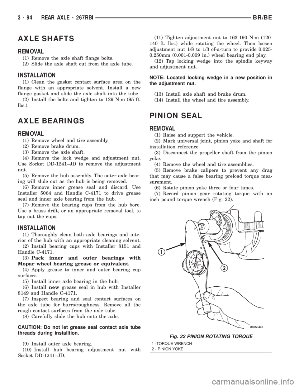
(7) Record pinion gear rotating torque with an
inch pound torque wrench (Fig. 22).
Fig. 22 PINION ROTATING TORQUE
1 -TORQUE WRENCH
2 - PINION YOKE
3 - 94 REAR AXLE - 267RBIBR/BE
Page 178 of 2255
AXLE SHAFTS
REMOVAL
(1) Remove the axle shaft flange bolts.
(2) Slide the axle shaft out from the axle tube.
INSTALLATION
(1) Clean the gasket contact surface area on the
flange with an appropriate solvent. Install a new
flange gasket and slide the axle shaft into the tube.
(2) Install the bolts and tighten to 129 N´m (95 ft.
lbs.).
AXLE BEARINGS
REMOVAL
(1) Remove wheel and tire assembly.
(2) Remove brake drum.
(3) Remove the axle shaft.
(4) Remove the lock wedge and adjustment nut.
Remove adjustment nut with Socket DD-1241-JD.
(5) Remove the hub assembly. The outer axle bear-
ing will slide out as the hub is being removed.
(6) Drive grease seal and inner bearing out of the
hub with Installer 5064 and Handle C-4171.
(7) Remove bearing cups from the hub with a
brass drift and a hammer.
INSTALLATION
(1) Thoroughly clean both axle bearings and inte-
rior of the hub with an appropriate cleaning solvent.
(2) Install bearing cups with Installer 8153 and
Handle C-4171.
(3) Pack inner and outer bearings with Mopar
wheel bearing grease or equivalent
(4) Apply lubricant to surface area of the bearing
cup.
(5) Install inner axle bearing in the hub.
(6) Install anewbearing grease seal with
Installer 8152 and Handle C-4171.
(7) Inspect bearing and seal contact surfaces on
the axle tube spindle for burrs and/or roughness.
Remove all the rough contact surfaces from the axle
spindle.
CAUTION: Do not let grease seal contact the axle
tube threads during installation.
(8) Carefully slide the hub onto the axle.
(9) Install outer axle bearing.
(10) Install hub bearing adjustment nut with
Socket DD-1241±JD.
(11) Tighten adjustment nut to 163-190 N´m (120-
140 ft. lbs.) while rotating the wheel.(12) Loosen adjustment nut 1/8 of-a-turn to pro-
vide 0.001-inch to 0.010-inch wheel bearing end play.
(13) Tap the locking wedge into the spindle key-
way and adjustment nut.
NOTE: Locate locking wedge in a new position in
the adjustment nut.
(14) Install axle shaft and brake drum.
(15) Install wheel and tire assembly.
PINION SEAL
REMOVAL
(1) Raise and support the vehicle.
(2) Mark the universal joint, pinion yoke, and pin-
ion shaft for installation reference.
(3) Disconnect the propeller shaft from the pinion
yoke. Secure the propeller shaft in an upright posi-
tion to prevent damage to the rear universal joint.
(4) Remove wheel and tire assemblies.
(5) Remove brake calipers to prevent any drag.
The drag may cause a false bearing preload torque
measurement.
(6) Rotate pinion yoke three or four times.
(7) Record the amount of torque necessary to
rotate the pinion gear with an inch pound dial-type
torque wrench.
(8) Hold the yoke with Holder 6719A and remove
the pinion shaft nut and washer.
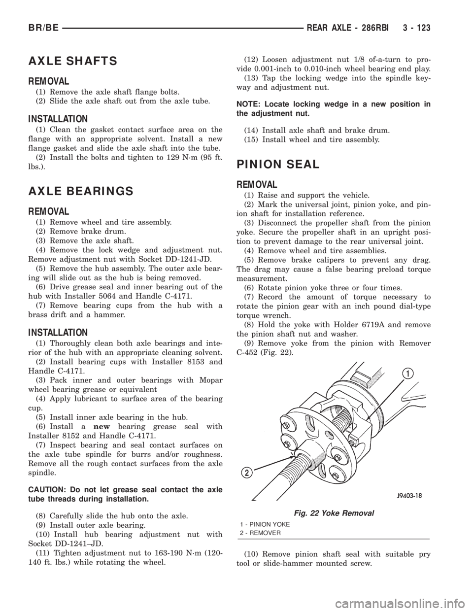
(9) Remove yoke from the pinion with Remover
C-452 (Fig. 22).
(10) Remove pinion shaft seal with suitable pry
tool or slide-hammer mounted screw.
Fig. 22 Yoke Removal
1 - PINION YOKE
2 - REMOVER
BR/BEREAR AXLE - 286RBI 3 - 123
Page 241 of 2255
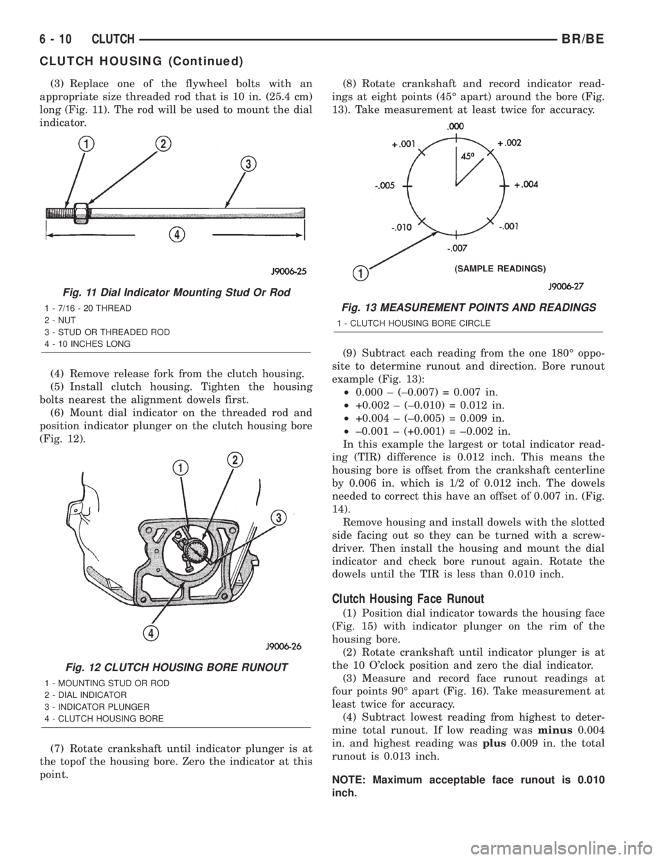
(3) Replace one of the flywheel bolts with an
appropriate size threaded rod that is 10 in. (25.4 cm)
long (Fig. 11). The rod will be used to mount the dial
indicator.
(4) Remove release fork from the clutch housing.
(5) Install clutch housing. Tighten the housing
bolts nearest the alignment dowels first.
(6) Mount dial indicator on the threaded rod and
position indicator plunger on the clutch housing bore
(Fig. 12).
(7) Rotate crankshaft until indicator plunger is at
the topof the housing bore. Zero the indicator at this
point.(8) Rotate crankshaft and record indicator read-
ings at eight points (45É apart) around the bore (Fig.
13). Take measurement at least twice for accuracy.
(9) Subtract each reading from the one 180É oppo-
site to determine runout and direction. Bore runout
example (Fig. 13):
²0.000 ± (±0.007) = 0.007 in.
²+0.002 ± (±0.010) = 0.012 in.
²+0.004 ± (±0.005) = 0.009 in.
²±0.001 ± (+0.001) = ±0.002 in.
In this example the largest or total indicator read-
ing (TIR) difference is 0.012 inch. This means the
housing bore is offset from the crankshaft centerline
by 0.006 in. which is 1/2 of 0.012 inch. The dowels
needed to correct this have an offset of 0.007 in. (Fig.
14).
Remove housing and install dowels with the slotted
side facing out so they can be turned with a screw-
driver. Then install the housing and mount the dial
indicator and check bore runout again. Rotate the
dowels until the TIR is less than 0.010 inch.
Clutch Housing Face Runout
(1) Position dial indicator towards the housing face
(Fig. 15) with indicator plunger on the rim of the
housing bore.
(2) Rotate crankshaft until indicator plunger is at
the 10 O'clock position and zero the dial indicator.
(3) Measure and record face runout readings at
four points 90É apart (Fig. 16). Take measurement at
least twice for accuracy.
(4) Subtract lowest reading from highest to deter-
mine total runout. If low reading wasminus0.004
in. and highest reading wasplus0.009 in. the total
runout is 0.013 inch.
NOTE: Maximum acceptable face runout is 0.010
inch.
Fig. 11 Dial Indicator Mounting Stud Or Rod
1 - 7/16 - 20 THREAD
2 - NUT
3 - STUD OR THREADED ROD
4 - 10 INCHES LONG
Fig. 12 CLUTCH HOUSING BORE RUNOUT
1 - MOUNTING STUD OR ROD
2 - DIAL INDICATOR
3 - INDICATOR PLUNGER
4 - CLUTCH HOUSING BORE
Fig. 13 MEASUREMENT POINTS AND READINGS
1 - CLUTCH HOUSING BORE CIRCLE
6 - 10 CLUTCHBR/BE
CLUTCH HOUSING (Continued)
Page 353 of 2255
(2) Use an ohmmeter to check the switch resis-
tances as shown in the Remote Radio Switch Test
chart. If the remote radio switch resistances check
OK, go to Step 3. If not OK, replace the faulty
switch.
REMOTE RADIO SWITCH TEST
SWITCH SWITCH POSITION RESISTANCE
Right
(White)Volume Up 7320 Ohms
Right
(White)Volume Down 1210 Ohms
Left
(Black)Seek Up 4530 Ohms
Left
(Black)Seek Down 2050 Ohms
Left
(Black)Pre-Set Station
Advance10 Ohms
(3) Check for continuity between the ground cir-
cuit cavity of the remote radio switch wire harness
connector and a good ground. There should be conti-
nuity. If OK, go to Step 4. If not OK, repair the open
ground circuit to ground as required.
(4) Disconnect the 18-way wire harness connector
from the Central Timer Module (CTM). Check for
continuity between the radio control mux circuit cav-
ity of the remote radio switch wire harness connector
and a good ground. There should be no continuity. If
OK, go to Step 5. If not OK, repair the shorted radio
control mux circuit as required.
(5) Check for continuity between the radio control
mux circuit cavities of the remote radio switch wire
harness connector and the 18-way CTM wire harness
connector. There should be continuity. If OK, refer to
the proper Diagnostic Procedures manual to test the
CTM and the Chrysler Collision Detection (CCD)
data bus. If not OK, repair the open radio control
mux circuit as required.
REMOVAL
(1) Disconnect and isolate the battery negative
cable.
(2) Remove the driver side airbag module from the
steering wheel. Refer to Electrical, Restraints for the
procedures.
(3) Remove the speed control switch located on the
same side of the steering wheel as the remote radio
switch that is being serviced. Refer to Electrical,
Speed Control for the procedures.
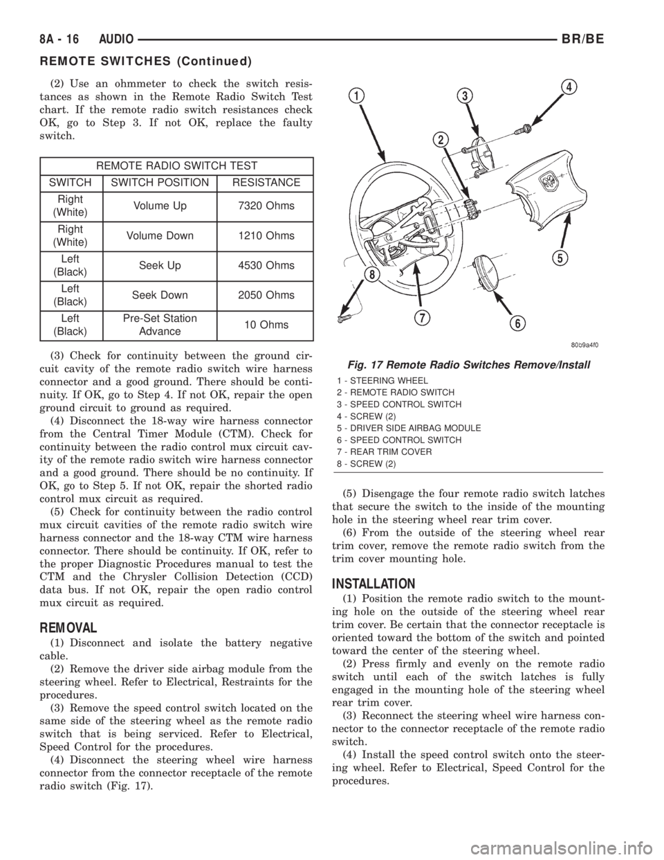
(4) Disconnect the steering wheel wire harness
connector from the connector receptacle of the remote
radio switch (Fig. 17).(5) Disengage the four remote radio switch latches
that secure the switch to the inside of the mounting
hole in the steering wheel rear trim cover.
(6) From the outside of the steering wheel rear
trim cover, remove the remote radio switch from the
trim cover mounting hole.
INSTALLATION
(1) Position the remote radio switch to the mount-
ing hole on the outside of the steering wheel rear
trim cover. Be certain that the connector receptacle is
oriented toward the bottom of the switch and pointed
toward the center of the steering wheel.
(2) Press firmly and evenly on the remote radio
switch until each of the switch latches is fully
engaged in the mounting hole of the steering wheel
rear trim cover.
(3) Reconnect the steering wheel wire harness con-
nector to the connector receptacle of the remote radio
switch.
(4) Install the speed control switch onto the steer-
ing wheel. Refer to Electrical, Speed Control for the
procedures.
Fig. 17 Remote Radio Switches Remove/Install
1 - STEERING WHEEL
2 - REMOTE RADIO SWITCH
3 - SPEED CONTROL SWITCH
4 - SCREW (2)
5 - DRIVER SIDE AIRBAG MODULE
6 - SPEED CONTROL SWITCH
7 - REAR TRIM COVER
8 - SCREW (2)
8A - 16 AUDIOBR/BE
REMOTE SWITCHES (Continued)