2002 DODGE RAM four wheel drive
[x] Cancel search: four wheel drivePage 607 of 2255

DRIVER AIRBAG
DESCRIPTION
The driver airbag protective trim cover is the most
visible part of the driver airbag. The airbag used in
this model is a Next Generation-type that complies
with revised federal airbag standards to deploy with
less force than those used in some prior models. The
driver airbag is located in the center of the steering
wheel, where it is secured with two screws to the
steering wheel armature. Concealed beneath the
driver airbag trim cover are the horn switch, the
folded airbag cushion, the airbag retainer or housing,
the airbag inflator, and the retainers that secure the
trim cover to the airbag housing. The resistive mem-
brane-type horn switch is secured with heat stakes to
the inside surface of the airbag trim cover, between
the trim cover and the folded airbag cushion. The air-
bag inflator is a conventional pyrotechnic-type unit
that is secured with nuts to four studs on the back of
the stamped metal airbag housing.
The driver airbag trim cover has locking blocks
molded into the back side of it that engage a lip
formed around the perimeter of the airbag housing.
Two stamped metal retainers then fit over the infla-
tor mounting studs on the back of the airbag housing
and tabs on the retainer are engaged in slots on the
inside of the trim cover, securely locking the cover
into place. One horn switch pigtail wire has an eyelet
terminal connector that is captured on the upper left
inflator mounting stud between the inflator and the
upper trim cover retainer. The connector insulator of
the other horn switch pigtail wire is routed between
the upper right inflator mounting stud and the infla-
tor, where it is captured by a small plastic retainer
that is pushed onto the stud. The driver airbag can-
not be repaired, and must be replaced if deployed or
in any way damaged. The driver airbag trim cover
and horn switch are available as a unit, and may be
disassembled from the driver airbag for service
replacement.
OPERATION
The driver airbag is deployed by an electrical sig-
nal generated by the Airbag Control Module (ACM)
through the driver airbag line 1 and line 2 (or squib)
circuits. When the ACM sends the proper electrical
signal to the airbag inflator, the electrical energy
generates enough heat to initiate a small pyrotechnic
charge which, in turn, ignites chemical pellets within
the inflator. Once ignited, these chemical pellets burn
rapidly and produce a large quantity of nitrogen gas.
The inflator is sealed to the back of the airbag hous-
ing and a diffuser in the inflator directs all of the
nitrogen gas into the airbag cushion, causing the
cushion to inflate. As the cushion inflates, the driverairbag trim cover will split at predetermined break-
out lines, then fold back out of the way along with
the horn switch. Following an airbag deployment, the
airbag cushion quickly deflates by venting the nitro-
gen gas towards the instrument panel through the
porous fabric material used on the steering wheel
side of the airbag cushion.
Some of the chemicals used to create the nitrogen
gas are considered hazardous in their solid state,
before they are burned, but they are securely sealed
within the airbag inflator. However, the nitrogen gas
that is produced when the chemicals are burned is
harmless. A small amount of residue from the burned
chemicals may cause some temporary discomfort if it
contacts the skin, eyes, or breathing passages. If skin
or eye irritation is noticed, rinse the affected area
with plenty of cool, clean water. If breathing pas-
sages are irritated, move to another area where there
is plenty of clean, fresh air to breath. If the irritation
is not alleviated by these actions, contact a physician.
REMOVAL
The following procedure is for replacement of a
faulty or damaged driver airbag. If the driver airbag
has been deployed, the clockspring and the steering
column assembly must also be replaced. (Refer to 8 -
ELECTRICAL/RESTRAINTS/CLOCKSPRING -
REMOVAL) (Refer to 19 - STEERING/COLUMN -
REMOVAL).
WARNING: DISABLE THE AIRBAG SYSTEM
BEFORE ATTEMPTING ANY STEERING WHEEL,
STEERING COLUMN, OR INSTRUMENT PANEL
COMPONENT DIAGNOSIS OR SERVICE. DISCON-
NECT AND ISOLATE THE BATTERY NEGATIVE
(GROUND) CABLE, THEN WAIT TWO MINUTES FOR
THE AIRBAG SYSTEM CAPACITOR TO DISCHARGE
BEFORE PERFORMING FURTHER DIAGNOSIS OR
SERVICE. THIS IS THE ONLY SURE WAY TO DIS-
ABLE THE AIRBAG SYSTEM. FAILURE TO TAKE
THE PROPER PRECAUTIONS COULD RESULT IN
ACCIDENTAL AIRBAG DEPLOYMENT AND POSSI-
BLE PERSONAL INJURY.
WARNING: WHEN REMOVING A DEPLOYED AIR-
BAG, RUBBER GLOVES, EYE PROTECTION, AND A
LONG-SLEEVED SHIRT SHOULD BE WORN. THERE
MAY BE DEPOSITS ON THE AIRBAG CUSHION AND
OTHER INTERIOR SURFACES. IN LARGE DOSES,
THESE DEPOSITS MAY CAUSE IRRITATION TO THE
SKIN AND EYES.
(1) Disconnect and isolate the battery negative
cable. If either of the airbags has not been deployed,
wait two minutes for the system capacitor to dis-
charge before further service.
8O - 14 RESTRAINTSBR/BE
Page 609 of 2255
WARNING: THE HORN SWITCH IS INTEGRAL TO
THE DRIVER AIRBAG UNIT. SERVICE OF THIS UNIT
SHOULD BE PERFORMED ONLY BY
DAIMLERCHRYSLER-TRAINED AND AUTHORIZED
DEALER SERVICE TECHNICIANS. FAILURE TO
TAKE THE PROPER PRECAUTIONS OR TO FOL-
LOW THE PROPER PROCEDURES COULD RESULT
IN ACCIDENTAL, INCOMPLETE, OR IMPROPER AIR-
BAG DEPLOYMENT AND POSSIBLE OCCUPANT
INJURIES.
(1) Disconnect and isolate the battery negative
cable. If either of the airbags has not been deployed,
wait two minutes for the system capacitor to dis-
charge before further service.
(2) Remove the driver airbag from the steering
wheel. (Refer to 8 - ELECTRICAL/RESTRAINTS/
DRIVER AIRBAG - REMOVAL).
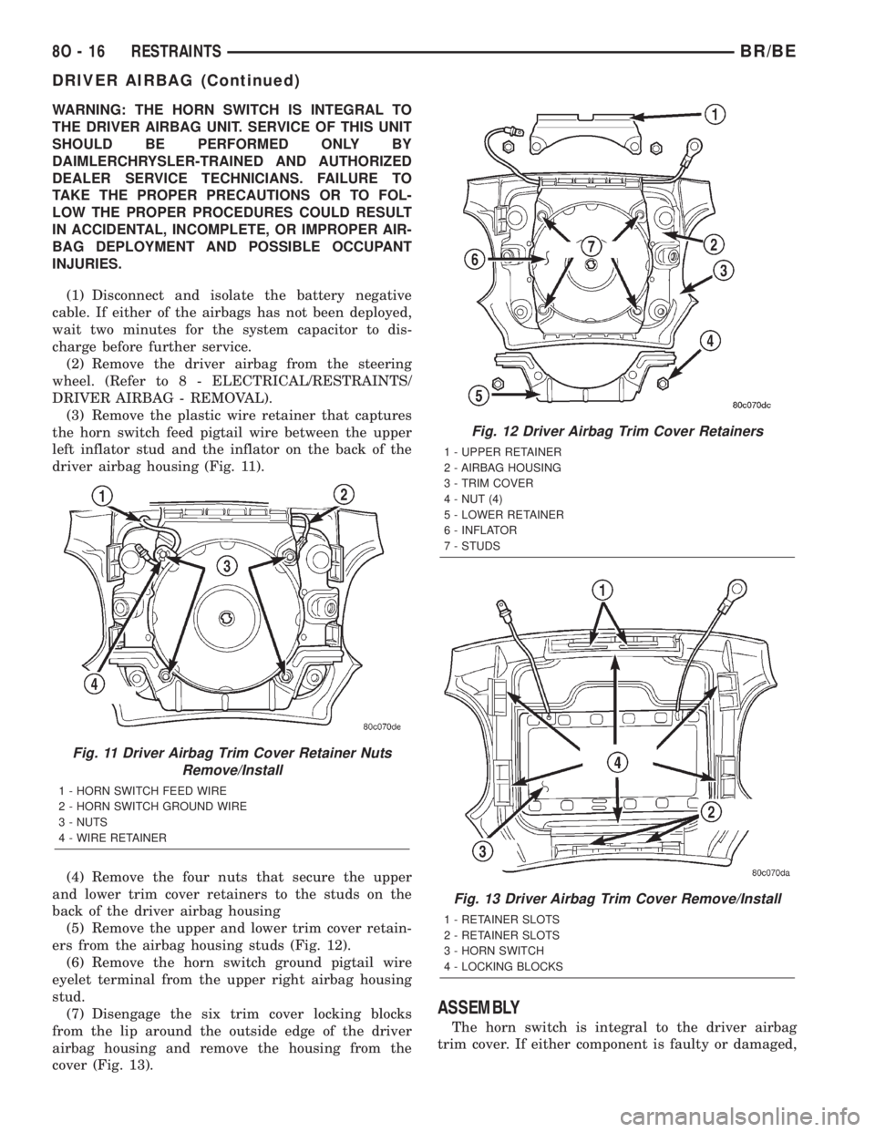
(3) Remove the plastic wire retainer that captures
the horn switch feed pigtail wire between the upper
left inflator stud and the inflator on the back of the
driver airbag housing (Fig. 11).
(4) Remove the four nuts that secure the upper
and lower trim cover retainers to the studs on the
back of the driver airbag housing
(5) Remove the upper and lower trim cover retain-
ers from the airbag housing studs (Fig. 12).
(6) Remove the horn switch ground pigtail wire
eyelet terminal from the upper right airbag housing
stud.
(7) Disengage the six trim cover locking blocks
from the lip around the outside edge of the driver
airbag housing and remove the housing from the
cover (Fig. 13).
ASSEMBLY
The horn switch is integral to the driver airbag
trim cover. If either component is faulty or damaged,
Fig. 11 Driver Airbag Trim Cover Retainer Nuts
Remove/Install
1 - HORN SWITCH FEED WIRE
2 - HORN SWITCH GROUND WIRE
3 - NUTS
4 - WIRE RETAINER
Fig. 12 Driver Airbag Trim Cover Retainers
1 - UPPER RETAINER
2 - AIRBAG HOUSING
3 - TRIM COVER
4 - NUT (4)
5 - LOWER RETAINER
6 - INFLATOR
7 - STUDS
Fig. 13 Driver Airbag Trim Cover Remove/Install
1 - RETAINER SLOTS
2 - RETAINER SLOTS
3 - HORN SWITCH
4 - LOCKING BLOCKS
8O - 16 RESTRAINTSBR/BE
DRIVER AIRBAG (Continued)
Page 1281 of 2255
(4) Connect the DRBIIItto the pressure trans-
ducer following the instructions supplied with the
DRB IIIt.
(5) Enter DRBIIItinto pressure reading mode and
test drive vehicle.
(6) The turbocharger boost pressure must be
between 110 - 138 kpa (16 - 20 psi.). If pressure read-
ings are lower than 110 kpa (16 psi.) inspect for the
following:
²Restricted air inlet system
²Leak in the charge air cooler system (Refer to 11
- EXHAUST SYSTEM/TURBOCHARGER SYSTEM/
CHARGE AIR COOLER AND PLUMBING - DIAG-
NOSIS AND TESTING)
²Turbocharger wastegate broken or misadjusted
²Turbocharger damaged (Refer to 11 - EXHAUST
SYSTEM/TURBOCHARGER SYSTEM/TURBO-
CHARGER - INSPECTION)
TURBOCHARGER
DESCRIPTION
The turbocharger is an exhaust-driven super-
charger which increases the pressure and density of
the air entering the engine. With the increase of air
entering the engine, more fuel can be injected into
the cylinders, which creates more power during com-
bustion.
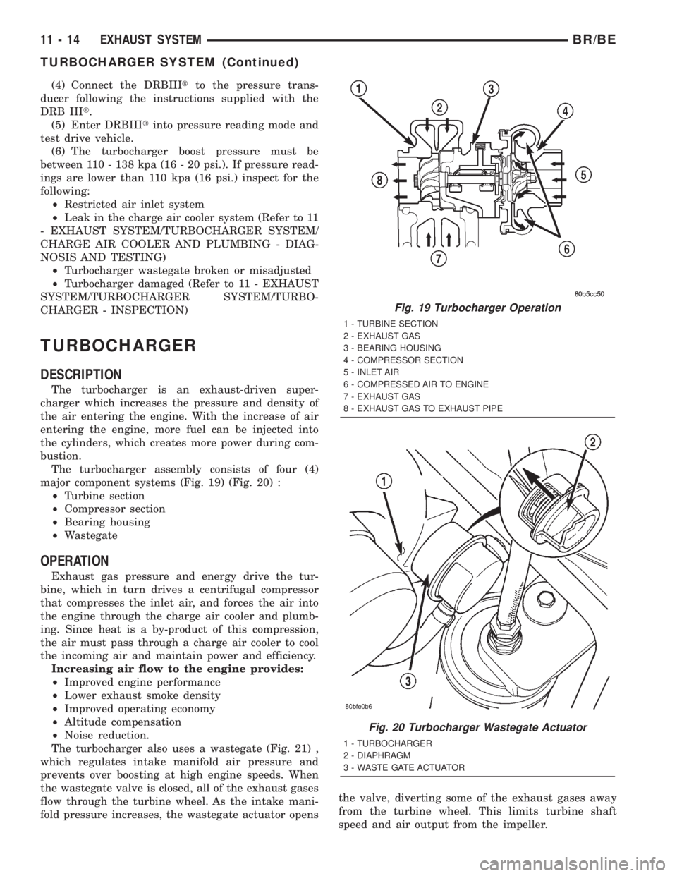
The turbocharger assembly consists of four (4)
major component systems (Fig. 19) (Fig. 20) :
²Turbine section
²Compressor section
²Bearing housing
²Wastegate
OPERATION
Exhaust gas pressure and energy drive the tur-
bine, which in turn drives a centrifugal compressor
that compresses the inlet air, and forces the air into
the engine through the charge air cooler and plumb-
ing. Since heat is a by-product of this compression,
the air must pass through a charge air cooler to cool
the incoming air and maintain power and efficiency.
Increasing air flow to the engine provides:
²Improved engine performance
²Lower exhaust smoke density
²Improved operating economy
²Altitude compensation
²Noise reduction.
The turbocharger also uses a wastegate (Fig. 21) ,
which regulates intake manifold air pressure and
prevents over boosting at high engine speeds. When
the wastegate valve is closed, all of the exhaust gases
flow through the turbine wheel. As the intake mani-
fold pressure increases, the wastegate actuator opensthe valve, diverting some of the exhaust gases away
from the turbine wheel. This limits turbine shaft
speed and air output from the impeller.
Fig. 19 Turbocharger Operation
1 - TURBINE SECTION
2 - EXHAUST GAS
3 - BEARING HOUSING
4 - COMPRESSOR SECTION
5 - INLET AIR
6 - COMPRESSED AIR TO ENGINE
7 - EXHAUST GAS
8 - EXHAUST GAS TO EXHAUST PIPE
Fig. 20 Turbocharger Wastegate Actuator
1 - TURBOCHARGER
2 - DIAPHRAGM
3 - WASTE GATE ACTUATOR
11 - 14 EXHAUST SYSTEMBR/BE
TURBOCHARGER SYSTEM (Continued)
Page 1457 of 2255
HARD SHIFTING
Hard shifting is usually caused by a low lubricant
level, improper or contaminated lubricants. The con-
sequence of using non-recommended lubricants is
noise, excessive wear, internal bind and hard shift-
ing. Substantial lubricant leaks can result in gear,
shift rail, synchro, and bearing damage. If a leak
goes undetected for an extended period, the first indi-
cations of component damage are usually hard shift-
ing and noise.
Component damage, incorrect clutch adjustment or
damaged clutch pressure plate or disc are additional
probable causes of increased shift effort. Incorrect
adjustment or a worn/damaged pressure plate or disc
can cause incorrect release. If clutch problem is
advanced, gear clash during shifts can result. Worn
or damaged synchro rings can cause gear clash when
shifting into any forward gear. In some new or
rebuilt transmissions, new synchro rings may tend to
stick slightly causing hard or noisy shifts. In most
cases this condition will decline as the rings wear-in.
TRANSMISSION NOISE
Most manual transmissions make some noise dur-
ing normal operation. Rotating gears generate a mild
whine that is audible, but generally only at extreme
speeds. Severe highly audible transmission noise is
generally the initial indicator of a lubricant problem.
Insufficient, improper or contaminated lubricant
will promote rapid wear of gears, synchros, shift
rails, forks and bearings. The overheating caused by
a lubricant problem, can also lead to gear breakage.
REMOVAL
(1) Disconnect battery negative cable.
(2) Shift transmission into Neutral.
(3) Remove shift boot screws from floorpan and
slide boot upward on the shift lever.
(4) Remove shift lever extension from shift tower
and lever assembly.
(5) Remove shift tower bolts holding tower to iso-
lator plate and transmission shift cover.
(6) Remove shift tower and isolator plate from
transmission shift cover.
(7) Raise and support vehicle.
(8) Remove skid plate, if equipped.
(9) Mark propeller shaft and axle yokes for instal-
lation reference and remove shaft/shafts.
(10) Remove exhaust system Y-pipe.
(11) Disconnect speed sensor and backup light
switch connectors.
(12) Support engine with safety stand and a wood
block.
(13) If transmission is to be disassembled for,
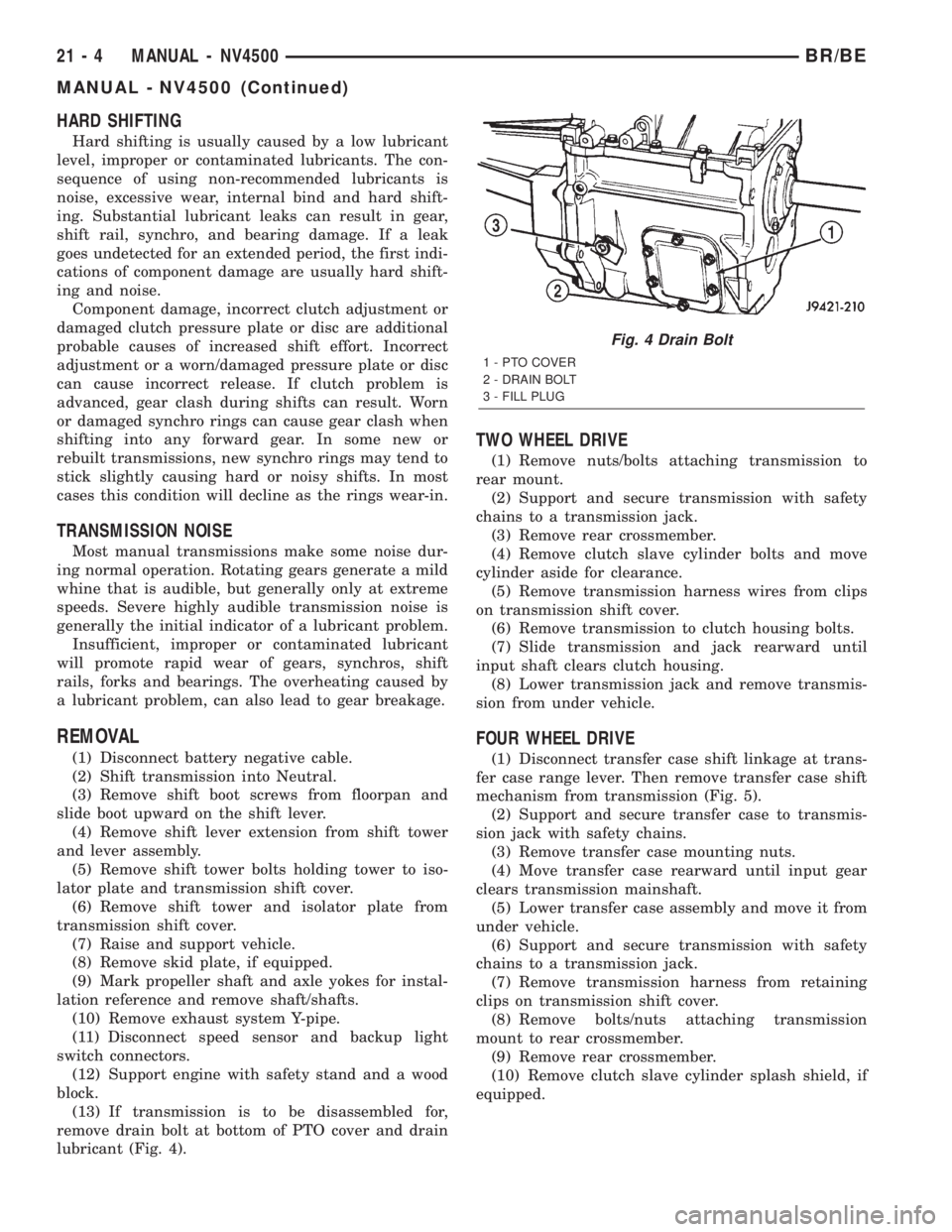
remove drain bolt at bottom of PTO cover and drain
lubricant (Fig. 4).
TWO WHEEL DRIVE
(1) Remove nuts/bolts attaching transmission to
rear mount.
(2) Support and secure transmission with safety
chains to a transmission jack.
(3) Remove rear crossmember.
(4) Remove clutch slave cylinder bolts and move
cylinder aside for clearance.
(5) Remove transmission harness wires from clips
on transmission shift cover.
(6) Remove transmission to clutch housing bolts.
(7) Slide transmission and jack rearward until
input shaft clears clutch housing.
(8) Lower transmission jack and remove transmis-
sion from under vehicle.
FOUR WHEEL DRIVE
(1) Disconnect transfer case shift linkage at trans-
fer case range lever. Then remove transfer case shift
mechanism from transmission (Fig. 5).
(2) Support and secure transfer case to transmis-
sion jack with safety chains.
(3) Remove transfer case mounting nuts.
(4) Move transfer case rearward until input gear
clears transmission mainshaft.
(5) Lower transfer case assembly and move it from
under vehicle.
(6) Support and secure transmission with safety
chains to a transmission jack.
(7) Remove transmission harness from retaining
clips on transmission shift cover.
(8) Remove bolts/nuts attaching transmission
mount to rear crossmember.
(9) Remove rear crossmember.
(10) Remove clutch slave cylinder splash shield, if
equipped.
Fig. 4 Drain Bolt
1 - PTO COVER
2 - DRAIN BOLT
3 - FILL PLUG
21 - 4 MANUAL - NV4500BR/BE
MANUAL - NV4500 (Continued)
Page 1490 of 2255

INSTALLATION
NOTE: If a new transmission is being installed, use
all components supplied with the new transmission.
For example, if a new shift tower is supplied with
the new transmission, do not re-use the original
shift tower.
(1) Apply light coat of Mopar high temperature
bearing grease or equivalent to contact surfaces of
the following components:
²input shaft splines.
²release bearing slide surface of front retainer.
²release bearing bore.
²release fork.
²release fork ball stud.
²propeller shaft slip yoke.
(2) Apply sealer to threads of bottom PTO cover
bolt and install bolt in case.
(3) Mount transmission on jack and position trans-
mission under vehicle.
(4) Raise transmission until input shaft is centered
in release bearing and clutch disc hub.
(5) Move transmission forward and start input
shaft in release bearing, clutch disc and pilot bush-
ing.
(6) Work transmission forward until seated against
clutch housing. Do not allow transmission to remain
unsupported after input shaft has entered clutch
disc.
(7) Install and tighten transmission-to-clutch hous-
ing bolts to 108 N´m (80 ft. lbs.).
(8) Install transmission mount on transmission or
rear crossmember.
(9) Install rear crossmember.
(10) Remove transmission jack and engine support
fixture.
(11) Position transmission harness wires in clips
on shift cover.
(12) Install clutch slave cylinder and install slave
cylinder shield, if equipped.
(13) Connect speed sensor and backup light switch
wires.
TWO WHEEL DRIVE
(1) Fill transmission with recommended lubricant.
Correct fill level is bottom edge of fill plug hole.
(2) Align and install propeller shaft.
(3) Lower vehicle.
(4) Clean the mating surfaces of shift tower, isola-
tor plate and shift cover with suitable wax and
grease remover.
(5) Apply Mopar Gasket Maker or equivalent to
the sealing surface of the shift cover. Do not over
apply sealant.(6) Install the isolator plate onto the shift cover,
metal side down.
(7) Install the shift tower onto the isolator plate.
No sealant is necessary between the shift tower and
the isolator plate.
(8) Verify that the shift tower, isolator plate and
the shift tower bushings are properly aligned.
(9) Install the bolts to hold the shift tower to the
isolator plate and the shift cover. Tighten the shift
tower bolts to 10.2±11.25 N´m (7.5±8.3 ft. lbs.).
(10) Install the shift lever extension onto the shift
tower and lever assembly.
(11) Install shift boot and bezel.
(12) Connect battery negative cable.
FOUR WHEEL DRIVE
(1) Install transfer case shift mechanism on trans-
mission.
(2) Install transfer case on transmission jack.
Secure transfer case to jack with safety chains.
(3) Raise jack and align transfer case input gear
with transmission mainshaft.
(4) Move transfer case forward and seat it on
adapter.
(5) Install and tighten transfer case attaching
nuts. Tighten nuts to 41-47 N´m (30-35 ft. lbs.) if
case has 3/8 studs or 30-41 N´m (22-30 ft. lbs.) if case
has 5/16 studs.
(6) Install transfer case shift mechanism to side of
transfer case.
(7) Connect transfer case shift lever to range lever
on transfer case.
(8) Align and connect propeller shafts.
(9) Fill transmission with required lubricant.
Check lubricant level in transfer case and add lubri-
cant if necessary.
(10) Install transfer case skid plate, if equipped
and crossmember. Tighten attaching bolts/nuts to 41
N´m (30 ft. lbs.).
(11) Install exhaust system components.
(12) Lower vehicle.
(13) Clean the mating surfaces of shift tower, iso-
lator plate and shift cover with suitable wax and
grease remover.
(14) Apply Mopar Gasket Maker or equivalent to
the sealing surface of the shift cover. Do not over
apply sealant.
(15) Install the isolator plate onto the shift cover,
metal side down.
(16) Install the shift tower onto the isolator plate.
No sealant is necessary between the shift tower and
the isolator plate.
(17) Verify that the shift tower, isolator plate and
the shift tower bushings are properly aligned.
BR/BEMANUAL - NV4500 21 - 37
MANUAL - NV4500 (Continued)
Page 1502 of 2255
TRANSMISSION NOISE
Most manual transmissions make some noise dur-
ing normal operation. Rotating gears generate a mild
whine that is audible, but generally only at extreme
speeds. Severe highly audible transmission noise is
generally the initial indicator of a lubricant problem.
Insufficient, improper or contaminated lubricant
will promote rapid wear of gears, synchros, shift
rails, forks and bearings. The overheating caused by
a lubricant problem, can also lead to gear breakage.
REMOVAL
NOTE: Use a heavy duty scissors style transmis-
sion jack for remove of the transmission.
(1) Disconnect battery negative cable.
(2) Shift transmission into Neutral.
(3) Remove screws attaching shift boot to floorpan.
Then slide boot upward on the shift lever.
(4) Remove the bolts holding the shift tower to the
isolator plate and transmission gear case.
(5) Remove the shift tower and isolator plate from
the transmission gear case.
(6) Raise and support vehicle.
(7) Remove skid plate, if equipped.
(8) Mark propeller shaft/shafts and axle yokes for
installation reference.
(9) Remove propeller shaft.
(10) Disconnect and remove exhaust system as
necessary.
(11) Disconnect wires at backup light switch.
(12) Support engine with adjustable safety stand
and wood block.
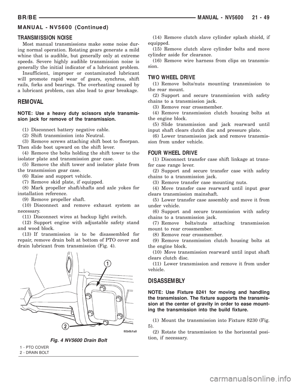
(13) If transmission is to be disassembled for
repair, remove drain bolt at bottom of PTO cover and
drain lubricant from transmission (Fig. 4).(14) Remove clutch slave cylinder splash shield, if
equipped.
(15) Remove clutch slave cylinder bolts and move
cylinder aside for clearance.
(16) Remove wire harness from clips on transmis-
sion.
TWO WHEEL DRIVE
(1) Remove bolts/nuts mounting transmission to
the rear mount.
(2) Support and secure transmission with safety
chains to a transmission jack.
(3) Remove rear crossmember.
(4) Remove transmission clutch housing bolts at
the engine block.
(5) Slide transmission and jack rearward until
input shaft clears clutch disc and pressure plate.
(6) Lower transmission jack and remove transmis-
sion from under vehicle.
FOUR WHEEL DRIVE
(1) Disconnect transfer case shift linkage at trans-
fer case range lever.
(2) Support and secure transfer case with safety
chains to a transmission jack.
(3) Remove transfer case mounting nuts.
(4) Move transfer case rearward until input gear
clears transmission mainshaft.
(5) Lower transfer case assembly and move it from
under vehicle.
(6) Support and secure transmission with safety
chains to a transmission jack.
(7) Remove bolts/nuts attaching transmission
mount to rear crossmember.
(8) Remove rear crossmember.
(9) Remove transmission clutch housing bolts at
the engine block.
(10) Move transmission rearward until input shaft
clears clutch disc.
(11) Lower transmission and remove it from under
vehicle.
DISASSEMBLY
NOTE: Use Fixture 8241 for moving and handling
the transmission. The fixture supports the transmis-
sion at the center of gravity in order to ease mount-
ing the transmission into the build fixture.
(1) Mount the transmission into Fixture 8230 (Fig.
5).
(2) Rotate the transmission to the horizontal posi-
tion, if necessary.
Fig. 4 NV5600 Drain Bolt
1 - PTO COVER
2 - DRAIN BOLT
BR/BEMANUAL - NV5600 21 - 49
MANUAL - NV5600 (Continued)
Page 1531 of 2255
(24) Install shift tower onto the transmission case
and tighten bolts to 9 N´m (7 ft.lbs.).
INSTALLATION
NOTE: If installing a new transmission, use all com-
ponents supplied with the transmission. If a new
shift tower is supplied with the new transmission,
do not re-use the original shift tower.
(1) Apply a light coat of Mopar high temperature
bearing grease or equivalent to contact surfaces of
following components:
²input shaft splines.
²release bearing slide surface of front retainer.
²release bearing bore.
²release fork.
²release fork ball stud.
²propeller shaft slip yoke.
(2) Apply sealer to threads of bottom PTO cover
bolt and install bolt in case.
(3) Mount transmission on jack and position trans-
mission under vehicle.
(4) Raise transmission until input shaft is centered
in clutch disc hub.
(5) Move transmission forward and start input
shaft in clutch disc and pilot bushing/bearing.
(6) Work transmission forward until seated against
engine block. Do not allow transmission to remain
unsupported after input shaft has entered clutch
disc.
(7) Install and tighten transmission-to-engine
block bolts.
(8) Install clutch slave cylinder.
(9) Connect backup light switch wires.
(10) Position transmission harness wires in clips
on transmission.(11) Install transmission mount on transmission or
rear crossmember.
(12) Install rear crossmember.
(13) Remove transmission jack and engine support
fixture.
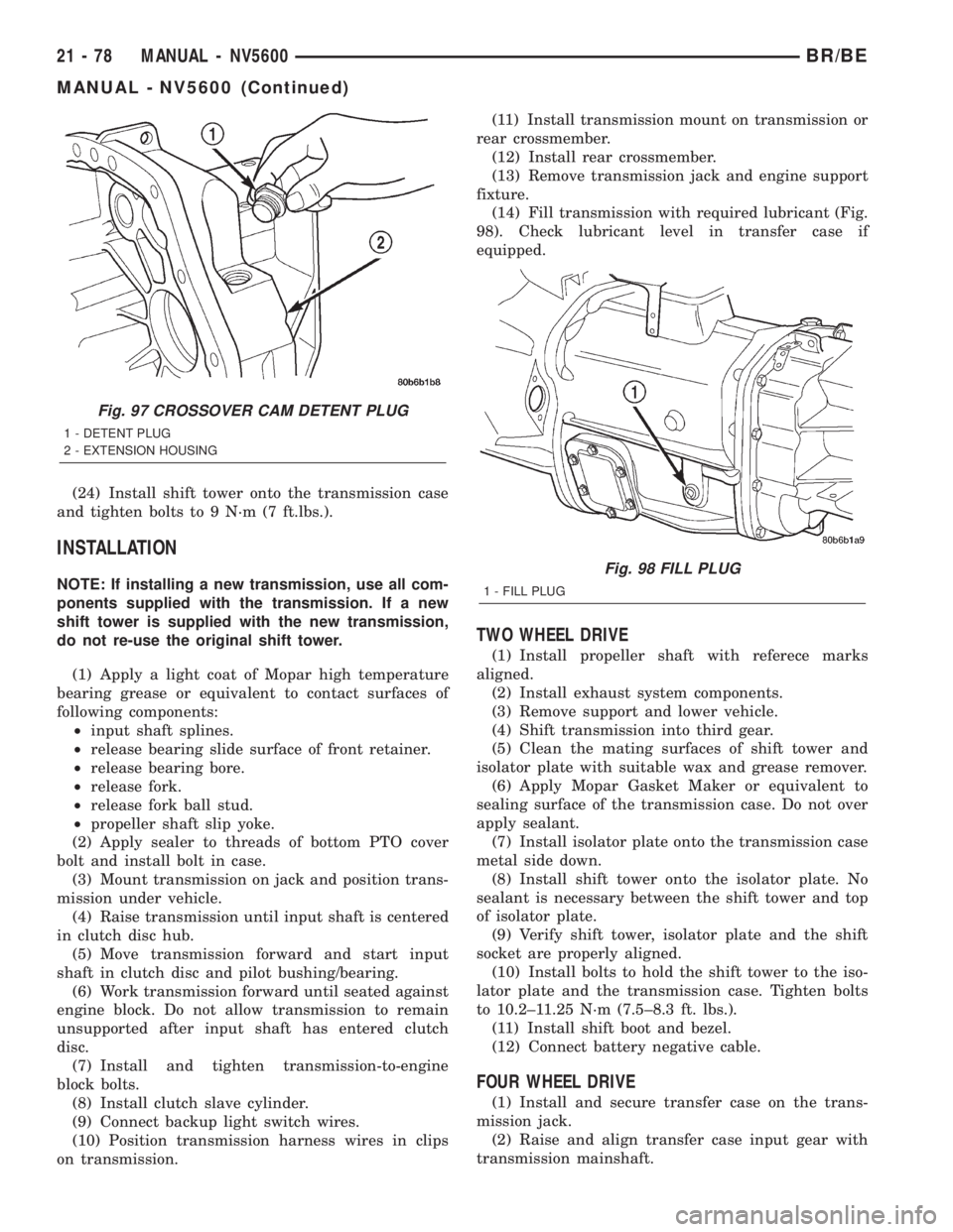
(14) Fill transmission with required lubricant (Fig.
98). Check lubricant level in transfer case if
equipped.
TWO WHEEL DRIVE
(1) Install propeller shaft with referece marks
aligned.
(2) Install exhaust system components.
(3) Remove support and lower vehicle.
(4) Shift transmission into third gear.
(5) Clean the mating surfaces of shift tower and
isolator plate with suitable wax and grease remover.
(6) Apply Mopar Gasket Maker or equivalent to
sealing surface of the transmission case. Do not over
apply sealant.
(7) Install isolator plate onto the transmission case
metal side down.
(8) Install shift tower onto the isolator plate. No
sealant is necessary between the shift tower and top
of isolator plate.
(9) Verify shift tower, isolator plate and the shift
socket are properly aligned.
(10) Install bolts to hold the shift tower to the iso-
lator plate and the transmission case. Tighten bolts
to 10.2±11.25 N´m (7.5±8.3 ft. lbs.).
(11) Install shift boot and bezel.
(12) Connect battery negative cable.
FOUR WHEEL DRIVE
(1) Install and secure transfer case on the trans-
mission jack.
(2) Raise and align transfer case input gear with
transmission mainshaft.
Fig. 97 CROSSOVER CAM DETENT PLUG
1 - DETENT PLUG
2 - EXTENSION HOUSING
Fig. 98 FILL PLUG
1 - FILL PLUG
21 - 78 MANUAL - NV5600BR/BE
MANUAL - NV5600 (Continued)
Page 1549 of 2255
FOURTH GEAR POWERFLOW
Fourth gear overdrive range is electronically con-
trolled and hydraulically activated. Various sensor
inputs are supplied to the powertrain control module
to operate the overdrive solenoid on the valve body.
The solenoid contains a check ball that opens and
closes a vent port in the 3-4 shift valve feed passage.
The overdrive solenoid (and check ball) are not ener-
gized in first, second, third, or reverse gear. The vent
port remains open, diverting line pressure from the
2-3 shift valve away from the 3-4 shift valve. The
overdrive control switch must be in the ON position
to transmit overdrive status to the PCM. A 3-4
upshift occurs only when the overdrive solenoid is
energized by the PCM. The PCM energizes the over-
drive solenoid during the 3-4 upshift. This causes the
solenoid check ball to close the vent port allowing
line pressure from the 2-3 shift valve to act directly
on the 3-4 upshift valve. Line pressure on the 3-4
shift valve overcomes valve spring pressure moving
the valve to the upshift position. This action exposes
the feed passages to the 3-4 timing valve, 3-4 quick
fill valve, 3-4 accumulator, and ultimately to the
overdrive piston. Line pressure through the timingvalve moves the overdrive piston into contact with
the overdrive clutch. The direct clutch is disengaged
before the overdrive clutch is engaged. The boost
valve provides increased fluid apply pressure to the
overdrive clutch during 3-4 upshifts, and when accel-
erating in fourth gear. The 3-4 accumulator cushions
overdrive clutch engagement to smooth 3-4 upshifts.
The accumulator is charged at the same time as
apply pressure acts against the overdrive piston.
DIAGNOSIS AND TESTING
DIAGNOSIS AND TESTING - AUTOMATIC
TRANSMISSION
Automatic transmission problems can be a result of
poor engine performance, incorrect fluid level, incor-
rect linkage or cable adjustment, band or hydraulic
control pressure adjustments, hydraulic system mal-
functions or electrical/mechanical component malfunc-
tions. Begin diagnosis by checking the easily
accessible items such as: fluid level and condition,
linkage adjustments and electrical connections. A road
test will determine if further diagnosis is necessary.
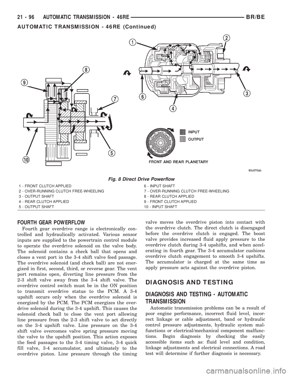
Fig. 8 Direct Drive Powerflow
1 - FRONT CLUTCH APPLIED 6 - INPUT SHAFT
2 - OVER-RUNNING CLUTCH FREE-WHEELING 7 - OVER-RUNNING CLUTCH FREE-WHEELING
3 - OUTPUT SHAFT 8 - REAR CLUTCH APPLIED
4 - REAR CLUTCH APPLIED 9 - FRONT CLUTCH APPLIED
5 - OUTPUT SHAFT 10 - INPUT SHAFT
21 - 96 AUTOMATIC TRANSMISSION - 46REBR/BE
AUTOMATIC TRANSMISSION - 46RE (Continued)