2002 DODGE RAM four wheel drive
[x] Cancel search: four wheel drivePage 1885 of 2255
Condition Possible Cause Correction
Noisy in, or jumps out of, four wheel
drive low range.1) Transfer case not completely
engaged in 4L position.1) With the transmission in
NEUTRAL, or the clutch depressed
in the case of a manual
transmission and the vehicle moving
under 3-4 km/h (2-3 mph), shift the
transfer case to NEUTRAL and then
shift into the 4L position.
2) Shift linkage out of adjustment. 2) Adjust linkage.
3) Shift linkage loose or binding. 3) Tighten, lubricate, or repair
linkage as necessary.
4) Range fork damaged, inserts
worn, or fork is binding on the shift
rail.4) Disassemble unit and repair as
necessary.
5) Low range gear worn or
damaged.5) Disassemble unit and repair as
necessary.
Lubricant leaking from output shaft
seal or vent.1) Transfer case overfilled. 1) Drain lubricant to the correct
level.
2) Vent closed or restricted. 2) Clear or replace vent as
necessary.
3) Output shaft seals damaged or
installed incorrectly.3) Replace seal as necessary.
Check to ensure that another
component, the propeller shaft slip
yoke for example, is not causing
damage to seal.
Abnormal tire wear. 1) Extended operation on hard, dry
surfaces in the 4H position.1) Operate vehicle in the 2H
position on hard, dry surfaces.
REMOVAL
(1) Raise and support vehicle.
(2) Remove skid plate, if equipped. (Refer to 13 -
FRAMES & BUMPERS/FRAME/TRANSFER CASE
SKID PLATE - REMOVAL)
(3) Position drain oil container under transfer
case.
(4) Remove transfer case drain plug and drain
lubricant into container.
(5) Disconnect vent hose and vacuum harness at
transfer case switch.
(6) Disconnect shift rod from grommet in transfer
case shift lever, or from floor shift arm whichever
provides easy access. Use channel lock style pliers to
press rod out of lever grommet.
(7) Support transmission with jack stand.
(8) Remove rear crossmember.
(9) Mark front and rear propeller shafts for assem-
bly reference.(10) Remove front and rear propeller shafts. (Refer
to 3 - DIFFERENTIAL & DRIVELINE/PROPELLER
SHAFT/PROPELLER SHAFT - REMOVAL)
(11) Support transfer case with suitable jack.
Secure transfer case to jack with safety chains.
(12) Remove nuts attaching transfer case to trans-
mission.
(13) Move transfer case assembly rearward until
free of transmission output shaft.
(14) Lower jack and move transfer case from
under vehicle.
DISASSEMBLY
Position transfer case in a shallow drain pan.
Remove drain plug and drain any remaining lubri-
cant remaining in case.
21 - 432 TRANSFER CASE - NV241LDBR/BE
TRANSFER CASE - NV241LD (Continued)
Page 1921 of 2255
DIAGNOSIS CHART
Condition Possible Cause Correction
Transfer Case difficult to shift or will
not shift into desired range.1) Vehicle speed too great to permit
shifting.1) Stop vehicle and shift into
desired range. Or, reduce speed to
below 3-4 km/h (2-3 mph) before
attempting the shift.
2) If vehicle was operated for an
extended period in 4H on a dry
paved surface, the driveline torque
load may be causing a bind.
2) Stop vehicle and shift the
transmission into neutral. Shift the
transfer case to 2H and operate
vehicle in 2H on dry paved surfaces.
3) Transfer case external shift
linkage binding.3) Lubricate, repair, or replace
linkage bushings, or tighten loose
components as necessary.
4) Insufficient or incorrect lubricant. 4) Drain and refill to edge of fill hole
with MoparTATF +4, type 9602,
Automatic Transmission fluid.
5) Internal components binding,
worn, or damaged.5) Disassemble the transfer case
and replace worn or damaged
components as necessary.
Transfer Case noisy in all operating
ranges.1) Insufficient or incorrect lubricant. 1) Drain and refill to edge of fill hole
with MoparTATF +4, type 9602,
Automatic Transmission fluid.
Noisy in, or jumps out of, four wheel
drive low range.1) Transfer case not completely
engaged in 4L position.1) With the transmission in
NEUTRAL, or the clutch depressed
in the case of a manual
transmission and the vehicle moving
under 3-4 km/h (2-3 mph), shift the
transfer case to NEUTRAL and then
shift into the 4L position.
2) Shift linkage out of adjustment. 2) Adjust linkage.
3) Shift linkage loose or binding. 3) Tighten, lubricate, or repair
linkage as necessary.
4) Range fork damaged, inserts worn,
or fork is binding on the shift rail.4) Disassemble unit and repair as
necessary.
5) Low range gear worn or
damaged.5) Disassemble unit and repair as
necessary.
Lubricant leaking from output shaft
seal or vent.1) Transfer case overfilled. 1) Drain lubricant to the correct
level.
2) Vent closed or restricted. 2) Clear or replace vent as
necessary.
3) Output shaft seals damaged or
installed incorrectly.3) Replace seal as necessary.
Check to ensure that another
component, the propeller shaft slip
yoke for example, is not causing
damage to seal.
Abnormal tire wear. 1) Extended operation on hard, dry
surfaces in the 4H position.1) Operate vehicle in the 2H
position on hard, dry surfaces.
21 - 468 TRANSFER CASE - NV241HDBR/BE
TRANSFER CASE - NV241HD (Continued)
Page 1961 of 2255
TIRES
DESCRIPTION
DESCRIPTION - SPARE TIRE - TEMPORARY
The temporary spare tire is designed for emer-
gency use only. The original tire should be repaired
or replaced at the first opportunity, then reinstalled.
Do not exceed speeds of 50 M.P.H. when using the
temporary spare tire. Refer to Owner's Manual for
complete details.
DESCRIPTION - TIRES
Tires are designed and engineered for each specific
vehicle. They provide the best overall performance
for normal operation. The ride and handling charac-
teristics match the vehicle's requirements. With
proper care they will give excellent reliability, trac-
tion, skid resistance, and tread life.
Driving habits have more effect on tire life than
any other factor. Careful drivers will obtain in most
cases, much greater mileage than severe use or care-
less drivers. A few of the driving habits which will
shorten the life of any tire are:
²Rapid acceleration
²Severe brake applications
²High speed driving
²Excessive speeds on turns
²Striking curbs and other obstacles
Radial-ply tires are more prone to irregular tread
wear. It is important to follow the tire rotation inter-
val shown in the section on Tire Rotation, (Refer to
22 - TIRES/WHEELS - STANDARD PROCEDURE).
This will help to achieve a greater tread life.
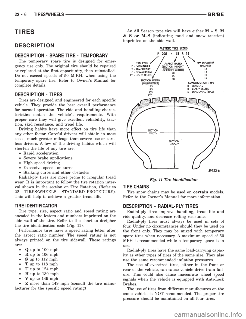
TIRE IDENTIFICATION
Tire type, size, aspect ratio and speed rating are
encoded in the letters and numbers imprinted on the
side wall of the tire. Refer to the chart to decipher
the tire identification code (Fig. 11).
Performance tires have a speed rating letter after
the aspect ratio number. The speed rating is not
always printed on the tire sidewall. These ratings
are:
²Qup to 100 mph
²Rup to 106 mph
²Sup to 112 mph
²Tup to 118 mph
²Uup to 124 mph
²Hup to 130 mph
²Vup to 149 mph
²Zmore than 149 mph (consult the tire manu-
facturer for the specific speed rating)An All Season type tire will have eitherM+S,M
&SorM±S(indicating mud and snow traction)
imprinted on the side wall.
TIRE CHAINS
Tire snow chains may be used oncertainmodels.
Refer to the Owner's Manual for more information.
DESCRIPTION - RADIAL-PLY TIRES
Radial-ply tires improve handling, tread life and
ride quality, and decrease rolling resistance.
Radial-ply tires must always be used in sets of
four. Under no circumstances should they be used on
the front only. They may be mixed with temporary
spare tires when necessary. A maximum speed of 50
MPH is recommended while a temporary spare is in
use.
Radial-ply tires have the same load-carrying capac-
ity as other types of tires of the same size. They also
use the same recommended inflation pressures.
The use of oversized tires, either in the front or
rear of the vehicle, can cause vehicle drive train fail-
ure. This could also cause inaccurate wheel speed
signals when the vehicle is equipped with Anti-Lock
Brakes.
The use of tires from different manufactures on the
same vehicle is NOT recommended. The proper tire
pressure should be maintained on all four tires.
Fig. 11 Tire Identification
22 - 6 TIRES/WHEELSBR/BE
Page 2134 of 2255
OPERATION
The compressor clutch assembly provides the
means to engage and disengage the compressor from
the engine serpentine accessory drive belt. When the
clutch coil is energized, it magnetically draws the
clutch into contact with the pulley and drives the
compressor shaft. When the coil is not energized, the
pulley freewheels on the clutch hub bearing, which is
part of the pulley. The compressor clutch and coil are
the only serviced parts on the compressor.
The compressor clutch engagement is controlled by
several components: the a/c heater mode control
switch, the a/c loss of charge switch, the a/c pressure
transducer, the compressor clutch relay, the evapora-
tor temperature sensor and the Powertrain Control
Module (PCM). The PCM may delay compressor
clutch engagement for up to thirty seconds(Refer to 8
- ELECTRICAL/ELECTRONIC CONTROL MOD-
ULES/POWERTRAIN CONTROL MODULE -
DESCRIPTION).
DIAGNOSIS AND TESTING - A/C COMPRESSOR
CLUTCH COIL
For circuit descriptions and diagrams, (Refer to
Appropriate Wiring Information). The battery must
be fully-charged before performing the following
tests. Refer to Battery for more information.
(1) Connect an ammeter (0 to 10 ampere scale) in
series with the clutch coil terminal. Use a voltmeter
(0 to 20 volt scale) with clip-type leads for measuring
the voltage across the battery and the compressor
clutch coil.(2) With the a/c heater mode control switch in any
A/C mode, and the blower motor switch in the lowest
speed position, start the engine and run it at normal
idle.
(3) The compressor clutch coil voltage should read
within 0.2 volts of the battery voltage. If there is
voltage at the clutch coil, but the reading is not
within 0.2 volts of the battery voltage, test the clutch
coil feed circuit for excessive voltage drop and repair
as required. If there is no voltage reading at the
clutch coil, use a DRB IIItscan tool and (Refer to
Appropriate Diagnostic Information) for testing of the
compressor clutch circuit. The following components
must be checked and repaired as required before you
can complete testing of the clutch coil:
²Fuses in the junction block and the Power Dis-
tribution Center (PDC)
²A/C Heater mode control switch
²Compressor clutch relay
²A/C High Pressure Switch
²A/C Low Pressure Switch
²Powertrain Control Module (PCM).
(4) The compressor clutch coil is acceptable if the
current draw measured at the clutch coil is 2.0 to 3.9
amperes with the electrical system voltage at 11.5 to
12.5 volts. This should only be checked with the work
area temperature at 21É C (70É F). If system voltage
is more than 12.5 volts, add electrical loads by turn-
ing on electrical accessories until the system voltage
drops below 12.5 volts.
(a) If the clutch coil current reading is four
amperes or more, the coil is shorted and should be
replaced.
(b) If the clutch coil current reading is zero, the
coil is open and should be replaced.
STANDARD PROCEDURE - A/C COMPRESSOR
CLUTCH BREAK-IN
After a new compressor clutch has been installed,
cycle the compressor clutch approximately twenty
times (five seconds on, then five seconds off). During
this procedure, set the A/C Heater control to the
Recirculation Mode, the blower motor switch in the
highest speed position, and the engine speed at 1500
to 2000 rpm. This procedure (burnishing) will seat
the opposing friction surfaces and provide a higher
compressor clutch torque capability.
REMOVAL
The refrigerant system can remain fully-charged
during compressor clutch, pulley, or coil replacement.
The compressor clutch can be serviced in the vehicle.
(1) Disconnect and isolate the battery negative
cable.
(2) On models with the diesel engine option,
remove the compressor from the engine. Do not
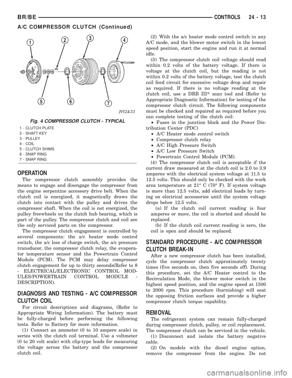
Fig. 4 COMPRESSOR CLUTCH - TYPICAL
1 - CLUTCH PLATE
2 - SHAFT KEY
3 - PULLEY
4 - COIL
5 - CLUTCH SHIMS
6 - SNAP RING
7 - SNAP RING
BR/BECONTROLS 24 - 13
A/C COMPRESSOR CLUTCH (Continued)
Page 2140 of 2255
(3) On vehicles with air conditioning, turn the
temperature control knob to the extreme counter
clockwise (Cool) position, and set the mode control
switch knob to the Bi-Level (A/C) position. The out-
side (recirculation) air door should be open to outside
air. If not OK, (Refer to 24 - HEATING & AIR CON-
DITIONING/CONTROLS - DIAGNOSIS AND TEST-
ING - VACUUM SYSTEM).
(4) Open the vehicle windows. Test the blower
motor operation in all speeds. If not OK, (Refer to 24
- HEATING & AIR CONDITIONING/DISTRIBU-
TION/BLOWER MOTOR - DIAGNOSIS AND TEST-
ING).
(5) On vehicles with air conditioning, the compres-
sor should be running and the air conditioning sys-
tem in operation unless the ambient air temperature
is below about -1É C (30É F). If not OK, (Refer to 24 -
HEATING & AIR CONDITIONING - DIAGNOSIS
AND TESTING - A/C PERFORMANCE).
(6) Check the mode control switch operation. The
heater and air conditioner systems should respond as
described in the owner's manual in the vehicle glove
box to each mode selected. Reduce the engine speed
to normal idle. The vacuum will be high at low idle
and the vacuum actuators should respond quickly. If
not OK, (Refer to 24 - HEATING & AIR CONDI-
TIONING/CONTROLS - DIAGNOSIS AND TEST-
ING - VACUUM SYSTEM).
(7) If the vacuum tests, and the electrical compo-
nent and circuit tests reveal no problems, disassem-
ble the HVAC housing to inspect for mechanical
misalignment or binding of the mode doors (Refer to
24 - HEATING & AIR CONDITIONING/DISTRIBU-
TION/HVAC HOUSING - DISASSEMBLY)
REMOVAL
WARNING: ON VEHICLES EQUIPPED WITH AIR-
BAGS, DISABLE THE AIRBAG SYSTEM BEFORE
ATTEMPTING ANY STEERING WHEEL, STEERING
COLUMN, OR INSTRUMENT PANEL COMPONENT
DIAGNOSIS OR SERVICE. DISCONNECT AND ISO-
LATE THE BATTERY NEGATIVE (GROUND) CABLE,
THEN WAIT TWO MINUTES FOR THE AIRBAG SYS-
TEM CAPACITOR TO DISCHARGE BEFORE PER-
FORMING FURTHER DIAGNOSIS OR SERVICE. THIS
IS THE ONLY SURE WAY TO DISABLE THE AIRBAG
SYSTEM. FAILURE TO TAKE THE PROPER PRE-
CAUTIONS COULD RESULT IN AN ACCIDENTAL
AIRBAG DEPLOYMENT AND POSSIBLE PERSONAL
INJURY.
(1) Disconnect and isolate the battery negative
cable.
(2) Reach under the instrument panel near the
driver side of the floor panel transmission tunnel andunplug the a/c heater control to HVAC housing vac-
uum harness connector.
(3) While still reaching under the instrument
panel, disengage the retainer on the a/c heater con-
trol half of the vacuum harness from the hole in the
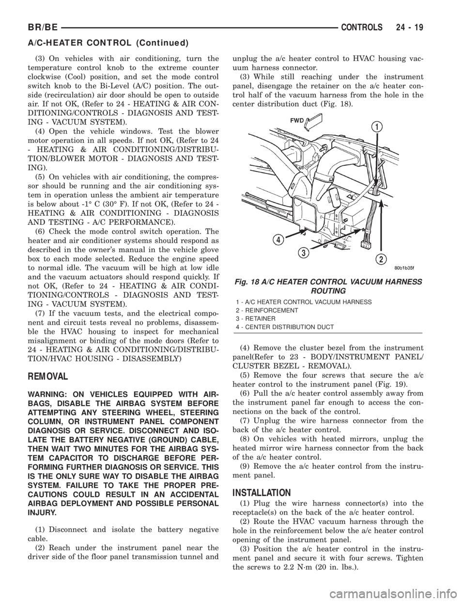
center distribution duct (Fig. 18).
(4) Remove the cluster bezel from the instrument
panel(Refer to 23 - BODY/INSTRUMENT PANEL/
CLUSTER BEZEL - REMOVAL).
(5) Remove the four screws that secure the a/c
heater control to the instrument panel (Fig. 19).
(6) Pull the a/c heater control assembly away from
the instrument panel far enough to access the con-
nections on the back of the control.
(7) Unplug the wire harness connector from the
back of the a/c heater control.
(8) On vehicles with heated mirrors, unplug the
heated mirror wire harness connector from the back
of the a/c heater control.
(9) Remove the a/c heater control from the instru-
ment panel.
INSTALLATION
(1) Plug the wire harness connector(s) into the
receptacle(s) on the back of the a/c heater control.
(2) Route the HVAC vacuum harness through the
hole in the reinforcement below the a/c heater control
opening of the instrument panel.
(3) Position the a/c heater control in the instru-
ment panel and secure it with four screws. Tighten
the screws to 2.2 N´m (20 in. lbs.).
Fig. 18 A/C HEATER CONTROL VACUUM HARNESS
ROUTING
1 - A/C HEATER CONTROL VACUUM HARNESS
2 - REINFORCEMENT
3 - RETAINER
4 - CENTER DISTRIBUTION DUCT
BR/BECONTROLS 24 - 19
A/C-HEATER CONTROL (Continued)
Page 2146 of 2255
DIAGNOSIS AND TESTING - BLOWER MOTOR
SWITCH
For circuit descriptions and diagrams, (Refer to
Appropriate Wiring Information).
WARNING: ON VEHICLES EQUIPPED WITH AIR-
BAGS, DISABLE THE AIRBAG SYSTEM BEFORE
ATTEMPTING ANY STEERING WHEEL, STEERING
COLUMN, OR INSTRUMENT PANEL COMPONENT
DIAGNOSIS OR SERVICE. DISCONNECT AND ISO-
LATE THE BATTERY NEGATIVE (GROUND) CABLE,
THEN WAIT TWO MINUTES FOR THE AIRBAG SYS-
TEM CAPACITOR TO DISCHARGE BEFORE PER-
FORMING FURTHER DIAGNOSIS OR SERVICE. THIS
IS THE ONLY SURE WAY TO DISABLE THE AIRBAG
SYSTEM. FAILURE TO TAKE THE PROPER PRE-
CAUTIONS COULD RESULT IN AN ACCIDENTAL
AIRBAG DEPLOYMENT AND POSSIBLE PERSONAL
INJURY.
(1) Check for battery voltage at the fuse in the
Power Distribution Center (PDC). If OK, go to Step
2. If not OK, repair the shorted circuit or component
as required and replace the faulty fuse.
(2) Turn the ignition switch to the Off position.
Disconnect and isolate the battery negative cable.
Remove the a/c heater control from the instrument
panel. (Refer to 24 - HEATING & AIR CONDITION-
ING/CONTROLS/A/C HEATER CONTROL -
REMOVAL) Check for continuity between the ground
circuit cavity of the a/c heater control wire harness
connector and a good ground. There should be conti-
nuity. If OK, go to Step 3. If not OK, repair the open
circuit to ground as required.
(3) With the a/c heater control wire harness con-
nector unplugged, place the a/c heater mode control
switch knob in any position except the Off position.
Check for continuity between the ground circuit ter-
minal and each of the blower motor driver circuit ter-
minals of the a/c heater control as you move the
blower motor switch knob to each of the four speed
positions. There should be continuity at each driver
circuit terminal in only one blower motor switch
speed position. If OK, test and repair the blower
driver circuits between the a/c heater control connec-
tor and the blower motor resistor as required. If not
OK, replace the faulty a/c heater control unit.
REMOVAL
The blower motor switch cannot be repaired and, if
faulty or damaged, the entire heater-only or a/c
heater control unit must be replaced. (Refer to 24 -
HEATING & AIR CONDITIONING/CONTROLS/A/C
HEATER CONTROL - REMOVAL) The blower motor
switch knob is serviced separately.
BLEND DOOR ACTUATOR
REMOVAL
WARNING: ON VEHICLES EQUIPPED WITH AIR-
BAGS, DISABLE THE AIRBAG SYSTEM BEFORE
ATTEMPTING ANY STEERING WHEEL, STEERING
COLUMN, OR INSTRUMENT PANEL COMPONENT
DIAGNOSIS OR SERVICE. DISCONNECT AND ISO-
LATE THE BATTERY NEGATIVE (GROUND) CABLE,
THEN WAIT TWO MINUTES FOR THE AIRBAG SYS-
TEM CAPACITOR TO DISCHARGE BEFORE PER-
FORMING FURTHER DIAGNOSIS OR SERVICE. THIS
IS THE ONLY SURE WAY TO DISABLE THE AIRBAG
SYSTEM. FAILURE TO TAKE THE PROPER PRE-
CAUTIONS COULD RESULT IN AN ACCIDENTAL
AIRBAG DEPLOYMENT AND POSSIBLE PERSONAL
INJURY.
(1) Turn the ignition switch to the run position.
(2) Locate the temperature control knob in the mid
(12 o'clock) position.
(3) Turn the ignition switch to the off position.
(4) Disconnect and isolate the battery negative
cable.
(5) Remove the instrument panel from the vehi-
cle(Refer to 23 - BODY/INSTRUMENT PANEL/IN-
STRUMENT PANEL ASSEMBLY - REMOVAL).
(6) Remove the HVAC housing from the vehicle.
(Refer to 24 - HEATING & AIR CONDITIONING/
DISTRIBUTION/HVAC HOUSING - REMOVAL)
(7) Unplug the wire harness connector from the
blend door actuator (Fig. 24).
(8) Remove the two mounting screws which secure
the actuator to the housing.
(9) Slide the blend door actuator off the blend door
shaft.
NOTE: A black plastic coupler may be attached to
the blend door shaft. Remove the coupler and
inspect for damage. Reinstall if there is no damage
found.
INSTALLATION
NOTE: Before installing the blend door actuator, be
certain that the blend door is not binding and is
capable of full travel in both directions.
(1) Align the actuator with the blend door shaft
and rotate the actuator to align it to the mounting
bosses on the HVAC housing.
(2) Align and install the actuator screws. Tighten
the mounting screws to 2.2 N´m (20 in. lbs.).
(3) Plug in the wire harness connector to the blend
door actuator.
BR/BECONTROLS 24 - 25
BLOWER MOTOR SWITCH (Continued)
Page 2228 of 2255
DOOR UPPER CORNER SEAL -
REMOVAL, FRONT...................23-153
DOUBLE CARDAN UNIVERSAL JOINTS -
ASSEMBLY..........................3-11
DOUBLE CARDAN UNIVERSAL JOINTS -
DISASSEMBLY........................3-10
DOUBLE INVERTED FLARING -
STANDARD PROCEDURE.................5-8
DRAIN AND REFILL - STANDARD
PROCEDURE, FLUID.................21-460
DRAIN MANIFOLD - DESCRIPTION, FUEL . . 14-89
DRAIN MANIFOLD - INSTALLATION,
FUEL..............................14-90
DRAIN MANIFOLD - OPERATION, FUEL . . . 14-89
DRAIN MANIFOLD - REMOVAL, FUEL.....14-90
DRAINBACK VALVE - DESCRIPTION,
TORQUE CONVERTER..........21-217,21-390
DRAINBACK VALVE - OPERATION,
TORQUE CONVERTER..........21-217,21-390
DRAINBACK VALVE - STANDARD
PROCEDURE, TORQUE CONVERTER....21-217,
21-390
DRAINING AT FUEL FILTER - STANDARD
PROCEDURES, WATER................14-61
DRAINING COOLING SYSTEM 5.9L
DIESEL ENGINE - STANDARD
PROCEDURE.........................7-15
DRAINING COOLING SYSTEM 5.9L/8.0L
ENGINES - STANDARD PROCEDURE......7-15
DRAIN/REFILL - STANDARD
PROCEDURE, FLUID.................21-497
DRAW TEST - STANDARD PROCEDURE,
IGNITION-OFF.......................8F-13
DRIVE - DIAGNOSIS AND TESTING,
VISCOUS FAN....................7-55,7-57
DRIVE BELT - DIAGNOSIS AND TESTING,
ACCESSORY.................7-24,7-27,7-30
DRIVE BELTS - 5.9L - INSTALLATION......7-26
DRIVE BELTS - 5.9L - REMOVAL.........7-26
DRIVE BELTS - 5.9L DIESEL -
INSTALLATION........................7-32
DRIVE BELTS - 5.9L DIESEL - REMOVAL . . . 7-32
DRIVE BELTS - 8.0L - INSTALLATION......7-29
DRIVE BELTS - 8.0L - REMOVAL.........7-29
DRIVE INDICATOR - DIAGNOSIS AND
TESTING, FOUR-WHEEL...............8J-29
DRIVE VISCOUS CLUTCH - 5.9L DIESEL
- DESCRIPTION, FAN...................7-56
DRIVE VISCOUS CLUTCH - 5.9L DIESEL
- OPERATION, FAN....................7-56
DRIVE VISCOUS CLUTCH - 5.9L/8.0L -
DESCRIPTION, FAN....................7-55
DRIVE VISCOUS CLUTCH - 5.9L/8.0L -
OPERATION, FAN......................7-55
DRIVER AIRBAG - ASSEMBLY..........8O-16
DRIVER AIRBAG - DESCRIPTION........8O-14
DRIVER AIRBAG - DISASSEMBLY........8O-15
DRIVER AIRBAG - INSTALLATION.......8O-17
DRIVER AIRBAG - OPERATION..........8O-14
DRIVER AIRBAG - REMOVAL...........8O-14
DRIVER POWER SEAT SWITCH -
DESCRIPTION.......................8N-17
DRIVER POWER SEAT SWITCH -
DIAGNOSIS AND TESTING.............8N-17
DRIVER POWER SEAT SWITCH -
INSTALLATION......................8N-18
DRIVER POWER SEAT SWITCH -
OPERATION.........................8N-17
DRIVER POWER SEAT SWITCH -
REMOVAL..........................8N-18
DRIVER SEAT HEATER SWITCH -
DESCRIPTION........................8G-7
DRIVER SEAT HEATER SWITCH -
INSTALLATION......................8G-10
DRIVER SEAT HEATER SWITCH -
OPERATION..........................8G-8
DRIVER SEAT HEATER SWITCH -
REMOVAL...........................8G-9
DROP - STANDARD PROCEDURE,
TESTING FOR A VOLTAGE
............8W-01-9
DUAL REAR WHEEL INSTALLATION -
STANDARD PROCEDURE
...............22-11
DUCT ADAPTER - INSTALLATION,
DEFROSTER AND DEMISTER
...........24-33
DUCT ADAPTER - REMOVAL,
DEFROSTER AND DEMISTER
...........24-33
DUCTS - INSTALLATION, DEFROSTER
AND DEMISTER
......................24-33DUCTS - INSTALLATION, INSTRUMENT
PANEL.............................24-37
DUCTS - INSTALLATION, INSTRUMENT
PANEL DEMISTER....................24-36
DUCTS - REMOVAL, DEFROSTER AND
DEMISTER..........................24-33
DUCTS - REMOVAL, INSTRUMENT
PANEL.............................24-37
DUCTS - REMOVAL, INSTRUMENT
PANEL DEMISTER....................24-36
EASY ENTRY SEAT TRACK -
INSTALLATION......................23-143
EASY ENTRY SEAT TRACK - REMOVAL . . 23-143
ECM - DESCRIPTION..................8E-13
ECM - OPERATION...................8E-13
EFFECTS OF INCORRECT FLUID LEVEL -
DIAGNOSIS AND TESTING......21-157,21-327
ELECTRICAL CONTROLS - DIAGNOSIS
AND TESTING, OVERDRIVE......21-191,21-344
ELECTRICAL TESTER - STANDARD
PROCEDURE, USING MIDTRONICS.......8F-15
ELECTRONIC GOVERNOR -
DESCRIPTION................21-152,21-322
ELECTRONIC GOVERNOR -
INSTALLATION................21-154,21-324
ELECTRONIC GOVERNOR - OPERATION . 21-153,
21-323
ELECTRONIC GOVERNOR - REMOVAL . . . 21-154,
21-324
ELECTROSTATIC DISCHARGE (ESD)
SENSITIVE DEVICES - STANDARD
PROCEDURE......................8W-01-8
ELEMENT - DESCRIPTION, HEATED SEAT . . . 8G-10
ELEMENT - INSTALLATION, AIR
CLEANER...........................9-130
ELEMENT - INSTALLATION, HEATED
SEAT ..............................8G-13
ELEMENT - OPERATION, HEATED SEAT . . . 8G-11
ELEMENT - REMOVAL, AIR CLEANER.....9-129
ELEMENT - REMOVAL, HEATED SEAT....8G-13
ELEMENT AND SENSOR - DIAGNOSIS
AND TESTING, HEATED SEAT...........8G-11
EMISSION CONTROL INFORMATION
(VECI) - DESCRIPTION, VEHICLE.......Intro.-3
END SPLASH SHIELDS - INSTALLATION,
FRONT.............................23-92
END SPLASH SHIELDS - REMOVAL,
FRONT.............................23-92
ENGINE - DESCRIPTION, COOLING
SYSTEM FLOW - 5.9L...................7-1
ENGINE - DESCRIPTION, FUEL
REQUIREMENTS - DIESEL...............0-3
ENGINE - DIAGNOSIS AND TESTING,
COOLING SYSTEM DIESEL..............7-13
ENGINE - DIAGNOSIS AND TESTING,
COOLING SYSTEM GAS.................7-7
ENGINE - DIAGNOSIS AND TESTING,
DIESEL.............................11-4
ENGINE - DIAGNOSIS AND TESTING,
GAS................................11-4
ENGINE - IGNITION COIL RESISTANCE,
8.0L V-10............................8I-4
ENGINE - INSTALLATION...............9-125
ENGINE - INSTALLATION, DIESEL........19-37
ENGINE - INSTALLATION, GASOLINE.....19-37
ENGINE - NEGATIVE CABLE
INSTALLATION, GASOLINE.............8F-22
ENGINE - NEGATIVE CABLE REMOVAL,
GASOLINE..........................8F-22
ENGINE - POSITIVE CABLE
INSTALLATION, GASOLINE.............8F-22
ENGINE - POSITIVE CABLE REMOVAL,
GASOLINE..........................8F-21
ENGINE - REMOVAL..................9-123
ENGINE - REMOVAL, DIESEL...........19-36
ENGINE - REMOVAL, GASOLINE.........19-35
ENGINE - SPARK PLUG CABLE ORDER,
8.0L V-10............................8I-3
ENGINE - STANDARD PROCEDURE,
DRAINING COOLING SYSTEM 5.9L
DIESEL.............................7-15
ENGINE - STANDARD PROCEDURE,
REFILLING COOLING SYSTEM 5.9L
DIESEL
.............................7-16
ENGINE - TORQUE, DIESEL
.............14-94
ENGINE - VISUAL INSPECTION, 8.0L
.....14-32
ENGINE 5.9L - DESCRIPTION
.............9-3
ENGINE 5.9L DIESEL - DESCRIPTION
.....9-115ENGINE 8.0L - DESCRIPTION............9-58
ENGINE BLOCK - CLEANING.........9-27,9-85
ENGINE BLOCK - INSPECTION.......9-27,9-85
ENGINE BLOCK HEATER - 5.9L -
DESCRIPTION........................7-44
ENGINE BLOCK HEATER - 5.9L -
INSTALLATION........................7-44
ENGINE BLOCK HEATER - 5.9L -
OPERATION..........................7-44
ENGINE BLOCK HEATER - 5.9L -
REMOVAL...........................7-44
ENGINE BLOCK HEATER - 5.9L DIESEL -
DESCRIPTION........................7-46
ENGINE BLOCK HEATER - 5.9L DIESEL -
INSTALLATION........................7-46
ENGINE BLOCK HEATER - 5.9L DIESEL -
OPERATION..........................7-46
ENGINE BLOCK HEATER - 5.9L DIESEL -
REMOVAL...........................7-46
ENGINE BLOCK HEATER - 8.0L -
DESCRIPTION........................7-45
ENGINE BLOCK HEATER - 8.0L -
INSTALLATION........................7-45
ENGINE BLOCK HEATER - 8.0L -
OPERATION..........................7-45
ENGINE BLOCK HEATER - 8.0L -
REMOVAL...........................7-45
ENGINE CONTROL MODULE -
INSTALLATION.......................8E-14
ENGINE CONTROL MODULE - REMOVAL . . 8E-14
ENGINE COOLANT - DESCRIPTION........7-39
ENGINE COOLANT - DESCRIPTION..........0-3
ENGINE COOLANT TEMP SENSOR - 5.9L
- DESCRIPTION.......................7-47
ENGINE COOLANT TEMP SENSOR - 5.9L
- INSTALLATION......................7-47
ENGINE COOLANT TEMP SENSOR - 5.9L
- OPERATION.........................7-47
ENGINE COOLANT TEMP SENSOR - 5.9L
- REMOVAL..........................7-47
ENGINE COOLANT THERMOSTAT - 5.9L -
DESCRIPTION........................7-48
ENGINE COOLANT THERMOSTAT - 5.9L -
INSTALLATION........................7-49
ENGINE COOLANT THERMOSTAT - 5.9L -
OPERATION..........................7-48
ENGINE COOLANT THERMOSTAT - 5.9L -
REMOVAL...........................7-48
ENGINE COOLANT THERMOSTAT - 5.9L
DIESEL - DESCRIPTION................7-53
ENGINE COOLANT THERMOSTAT - 5.9L
DIESEL - INSTALLATION................7-54
ENGINE COOLANT THERMOSTAT - 5.9L
DIESEL - OPERATION..................7-53
ENGINE COOLANT THERMOSTAT - 5.9L
DIESEL - REMOVAL....................7-54
ENGINE COOLANT THERMOSTAT - 8.0L -
DESCRIPTION........................7-51
ENGINE COOLANT THERMOSTAT - 8.0L -
INSTALLATION........................7-52
ENGINE COOLANT THERMOSTAT - 8.0L -
OPERATION..........................7-51
ENGINE COOLANT THERMOSTAT - 8.0L -
REMOVAL...........................7-51
ENGINE DATA PLATE - DESCRIPTION.....9-129
ENGINE DIAGNOSIS - INTRODUCTION -
DIAGNOSIS AND TESTING...........9-3,9-58
ENGINE DIAGNOSIS - LUBRICATION -
DIAGNOSIS AND TESTING...........9-63,9-8
ENGINE DIAGNOSIS - MECHANICAL -
DIAGNOSIS AND TESTING......9-116,9-6,9-61
ENGINE DIAGNOSIS - PERFORMANCE -
DIAGNOSIS AND TESTING...........9-4,9-59
ENGINE FIRING ORDER, 5.9L V-8
ENGINES............................8I-3
ENGINE OIL - DESCRIPTION...........0-4,0-5
ENGINE OIL - STANDARD PROCEDURE . . . 9-101,
9-45
ENGINE OIL LEAKS - DIAGNOSIS AND
TESTING........................9-43,9-99
ENGINE OIL LEVEL - STANDARD
PROCEDURE
........................9-178
ENGINE OIL PRESSURE - DIAGNOSIS
AND TESTING
..............9-101,9-178,9-45
ENGINE OIL SERVICE - STANDARD
PROCEDURE
........................9-178
ENGINE, SPECIAL TOOLS - 5.9L
..........9-18
ENGINE, SPECIAL TOOLS - 5.9L DIESEL
. . 9-128
BR/BEINDEX 11
Description Group-Page Description Group-Page Description Group-Page
Page 2230 of 2255
FLOW - DIAGNOSIS AND TESTING,
RADIATOR COOLANT..........7-58,7-60,7-62
FLOW AND PRESSURE - DIAGNOSIS
AND TESTING, POWER STEERING........19-4
FLUID - DESCRIPTION, AUTOMATIC
TRANSMISSION.......................0-6
FLUID - DIAGNOSIS AND TESTING,
CAUSES OF BURNT............21-157,21-327
FLUID - OPERATION, AUTOMATIC
TRANSMISSION.......................0-6
FLUID AND FILTER REPLACEMENT -
STANDARD PROCEDURE........21-158,21-329
FLUID CAPACITIES, SPECIFICATIONS.......0-6
FLUID CONTAMINATION - DIAGNOSIS
AND TESTING................21-157,21-327
FLUID CONTAMINATION - DIAGNOSIS
AND TESTING, BRAKE..................5-15
FLUID DRAIN AND REFILL - STANDARD
PROCEDURE.......................21-460
FLUID DRAIN/REFILL - STANDARD
PROCEDURE.......................21-497
FLUID INDICATOR - DESCRIPTION,
WASHER...........................8J-35
FLUID INDICATOR - DIAGNOSIS AND
TESTING, WASHER...................8J-35
FLUID INDICATOR - OPERATION,
WASHER...........................8J-35
FLUID LEAK - DIAGNOSIS AND TESTING,
CONVERTER HOUSING.........21-101,21-273
FLUID LEVEL - DIAGNOSIS AND
TESTING, EFFECTS OF INCORRECT.....21-157,
21-327
FLUID LEVEL - STANDARD PROCEDURE,
BRAKE...............................5-15
FLUID LEVEL CHECK - STANDARD
PROCEDURE.................21-157,21-328
FLUID LEVEL SWITCH - DESCRIPTION,
WASHER............................8R-7
FLUID LEVEL SWITCH - INSTALLATION,
WASHER............................8R-8
FLUID LEVEL SWITCH - OPERATION,
WASHER............................8R-7
FLUID LEVEL SWITCH - REMOVAL,
WASHER............................8R-8
FLUID RESERVOIR - INSTALLATION.......5-15
FLUID RESERVOIR - REMOVAL..........5-15
FLUID, SPECIFICATIONS - BRAKE.........5-15
FLUSH MEASUREMENTS,
SPECIFICATIONS - BODY GAP..........23-56
FLUSHING - STANDARD PROCEDURE,
COOLING SYSTEM CLEANING/
REVERSE............................7-17
FLUSHING COOLERS AND TUBES - WITH
RADIATOR IN-TANK TRANSMISSION
OIL COOLER - STANDARD
PROCEDURE.................7-78,7-82,7-84
FLUSHING COOLERS AND TUBES -
WITHOUT RADIATOR IN-TANK
TRANSMISSION OIL COOLER -
STANDARD PROCEDURE.......7-79,7-82,7-85
FLUSHING POWER STEERING SYSTEM -
STANDARD PROCEDURE...............19-34
FLYWHEEL - ASSEMBLY................6-14
FLYWHEEL - DIAGNOSIS AND TESTING....6-13
FLYWHEEL - DISASSEMBLY.............6-13
FOG LAMP - DIAGNOSIS AND TESTING . . . 8L-10
FOG LAMP - INSTALLATION............8L-11
FOG LAMP - REMOVAL................8L-11
FOG LAMP UNIT - ADJUSTMENTS.......8L-13
FOG LAMP UNIT - INSTALLATION........8L-12
FOG LAMP UNIT - REMOVAL...........8L-12
FORE/AFT - ADJUSTMENT, FRONT DOOR . . 23-69
FORM-IN-PLACE GASKETS AND
SEALERS - STANDARD PROCEDURE . 9-10,9-122,
9-66
FOUR-WHEEL DRIVE INDICATOR -
DIAGNOSIS AND TESTING..............8J-29
FRAME - INSTALLATION, GRILLE........23-92
FRAME - REMOVAL, GRILLE............23-91
FRAME DIMENSION, SPECIFICATIONS.....13-8
FRAME SERVICE, DESCRIPTION..........13-7
FRONT - 2500 - INSTALLATION..........5-23
FRONT - 2500 - REMOVAL
..............5-22
FRONT - 3500 - INSTALLATION
..........5-23
FRONT - 3500 - REMOVAL
..............5-22
FRONT - DESCRIPTION, CRANKSHAFT
OIL SEAL
............................9-32
FRONT - INSTALLATION
............5-14,5-26FRONT - INSTALLATION...............22-12
FRONT - INSTALLATION, CRANKSHAFT
OIL SEAL.......................9-160,9-32
FRONT - INSTALLATION, PROPELLER
SHAFT...............................3-7
FRONT - OPERATION, CRANKSHAFT OIL
SEAL...............................9-32
FRONT - REMOVAL................5-11,5-24
FRONT - REMOVAL, CRANKSHAFT OIL
SEAL..........................9-160,9-32
FRONT - REMOVAL, PROPELLER SHAFT....3-6
FRONT AIR DAM - INSTALLATION........13-2
FRONT AIR DAM - REMOVAL............13-2
FRONT AXLE - 248FBI - ADJUSTMENTS....3-19
FRONT AXLE - 248FBI - DESCRIPTION.....3-14
FRONT AXLE - 248FBI - INSTALLATION....3-18
FRONT AXLE - 248FBI - OPERATION......3-14
FRONT AXLE - 248FBI - REMOVAL........3-18
FRONT AXLE, 248FBI..................3-27
FRONT AXLE, SPECIAL TOOLS...........3-27
FRONT BEARING - INSTALLATION,
OUTPUT SHAFT...............21-171,21-342
FRONT BEARING - REMOVAL, OUTPUT
SHAFT......................21-171,21-342
FRONT BUMPER - INSTALLATION.........13-4
FRONT BUMPER - REMOVAL............13-4
FRONT BUMPER - SPORT -
INSTALLATION........................13-5
FRONT BUMPER - SPORT - REMOVAL......13-5
FRONT CLUTCH - ASSEMBLY....21-162,21-333
FRONT CLUTCH - DESCRIPTION . . 21-160,21-330
FRONT CLUTCH - DISASSEMBLY . 21-161,21-331
FRONT CLUTCH - INSPECTION . . . 21-162,21-332
FRONT CLUTCH - OPERATION . . . 21-160,21-330
FRONT COVER INSTALLED -
INSTALLATION, FRONT OIL SEAL.........9-89
FRONT COVER INSTALLED - REMOVAL,
FRONT OIL SEAL......................9-89
FRONT COVER REMOVED -
INSTALLATION, FRONT OIL SEAL.........9-90
FRONT COVER REMOVED - REMOVAL,
FRONT OIL SEAL......................9-89
FRONT DOOR FORE/AFT - ADJUSTMENT . . 23-69
FRONT DOOR GLASS RUN
WEATHERSTRIP - INSTALLATION.......23-153
FRONT DOOR GLASS RUN
WEATHERSTRIP - REMOVAL...........23-152
FRONT DOOR INNER BELT
WEATHERSTRIP - INSTALLATION.......23-153
FRONT DOOR INNER BELT
WEATHERSTRIP - REMOVAL...........23-153
FRONT DOOR IN/OUT - ADJUSTMENT....23-70
FRONT DOOR LATCH - ADJUSTMENT.....23-73
FRONT DOOR OUTER BELT
WEATHERSTRIP - INSTALLATION.......23-153
FRONT DOOR OUTER BELT
WEATHERSTRIP - REMOVAL...........23-153
FRONT DOOR SECOND WEATHERSTRIP -
INSTALLATION......................23-154
FRONT DOOR SECOND WEATHERSTRIP -
REMOVAL.........................23-154
FRONT DOOR SPEAKER - INSTALLATION . . 8A-19
FRONT DOOR SPEAKER - REMOVAL.....8A-19
FRONT DOOR UP/DOWN - ADJUSTMENT . . 23-70
FRONT DOOR UPPER CORNER SEAL -
INSTALLATION......................23-154
FRONT DOOR UPPER CORNER SEAL -
REMOVAL.........................23-153
FRONT END SPLASH SHIELDS -
INSTALLATION.......................23-92
FRONT END SPLASH SHIELDS -
REMOVAL..........................23-92
FRONT FASCIA - INSTALLATION
..........13-2
FRONT FASCIA - REMOVAL
..............13-2
FRONT FASCIA - SPORT - INSTALLATION
. . 13-3
FRONT FASCIA - SPORT - REMOVAL
......13-3
FRONT FENDER - INSTALLATION, LEFT
. . . 23-93
FRONT FENDER - INSTALLATION, RIGHT
. . 23-94
FRONT FENDER - REMOVAL, LEFT
.......23-93
FRONT FENDER - REMOVAL, RIGHT
......23-94
FRONT LOWER FASCIA - INSTALLATION
. . . 13-3
FRONT LOWER FASCIA - REMOVAL
.......13-3
FRONT MOUNT - INSTALLATION
....9-174,9-42,
9-98
FRONT MOUNT - REMOVAL
....9-173,9-41,9-97
FRONT OIL SEAL - FRONT COVER
INSTALLED - INSTALLATION
.............9-89FRONT OIL SEAL - FRONT COVER
INSTALLED - REMOVAL................9-89
FRONT OIL SEAL - FRONT COVER
REMOVED - INSTALLATION..............9-90
FRONT OIL SEAL - FRONT COVER
REMOVED - REMOVAL.................9-89
FRONT OUTPUT SHAFT SEAL -
INSTALLATION................21-461,21-498
FRONT OUTPUT SHAFT SEAL -
REMOVAL...................21-461,21-498
FRONT PARKING BRAKE CABLE -
INSTALLATION........................5-30
FRONT PARKING BRAKE CABLE -
REMOVAL...........................5-29
FRONT SEAT BELT BUCKLE -
INSTALLATION......................8O-20
FRONT SEAT BELT BUCKLE - REMOVAL . . 8O-20
FRONT SERVO - ASSEMBLY.....21-164,21-335
FRONT SERVO - CLEANING.....21-164,21-334
FRONT SERVO - DESCRIPTION . . . 21-164,21-334
FRONT SERVO - DISASSEMBLY . . 21-164,21-334
FRONT SERVO - INSPECTION....21-164,21-335
FRONT SERVO - OPERATION....21-164,21-334
FRONT SUSPENSION, SPECIAL TOOLS -
INDEPENDENT.........................2-9
FRONT TOW HOOK - INSTALLATION......13-10
FRONT TOW HOOK - REMOVAL.........13-10
FRONT WHEEL SPEED SENSOR -
DESCRIPTION........................5-38
FRONT WHEEL SPEED SENSOR -
OPERATION...........................5-38
FUEL DELIVERY - SPECIFICATIONS,
TORQUE............................14-4
FUEL DELIVERY SYSTEM -
DESCRIPTION........................14-2
FUEL DELIVERY SYSTEM -
DESCRIPTION, DIESEL................14-55
FUEL DELIVERY SYSTEM - OPERATION....14-2
FUEL DRAIN MANIFOLD - DESCRIPTION . . 14-89
FUEL DRAIN MANIFOLD - INSTALLATION . . 14-90
FUEL DRAIN MANIFOLD - OPERATION....14-89
FUEL DRAIN MANIFOLD - REMOVAL.....14-90
FUEL FILL DOOR - INSTALLATION.......23-95
FUEL FILL DOOR - REMOVAL...........23-95
FUEL FILLER CAP - DESCRIPTION.......25-34
FUEL FILLER CAP - OPERATION.........25-34
FUEL FILLER CAP - REMOVAL/
INSTALLATION.......................25-34
FUEL FILTER - STANDARD
PROCEDURES, WATER DRAINING AT.....14-61
FUEL FILTER / WATER SEPARATOR -
DESCRIPTION.......................14-63
FUEL FILTER / WATER SEPARATOR -
INSTALLATION.......................14-65
FUEL FILTER / WATER SEPARATOR -
OPERATION.........................14-63
FUEL FILTER / WATER SEPARATOR -
REMOVAL..........................14-64
FUEL FILTER/PRESSURE REGULATOR -
DESCRIPTION........................14-5
FUEL FILTER/PRESSURE REGULATOR -
INSTALLATION........................14-7
FUEL FILTER/PRESSURE REGULATOR -
OPERATION..........................14-5
FUEL FILTER/PRESSURE REGULATOR -
REMOVAL...........................14-5
FUEL GAUGE - DESCRIPTION...........8J-19
FUEL GAUGE - OPERATION.............8J-20
FUEL GAUGE SENDING UNIT -
DIAGNOSIS AND TESTING..............14-7
FUEL HEATER - DESCRIPTION
..........14-66
FUEL HEATER - DIAGNOSIS AND
TESTING
...........................14-66
FUEL HEATER - OPERATION
............14-66
FUEL HEATER - REMOVAL/INSTALLATION
. 14-67
FUEL HEATER RELAY - DESCRIPTION
....14-67
FUEL HEATER RELAY - DIAGNOSIS AND
TESTING
...........................14-68
FUEL HEATER RELAY - INSTALLATION
....14-69
FUEL HEATER RELAY - OPERATION
......14-67
FUEL HEATER RELAY - REMOVAL
........14-69
FUEL INDICATOR - DESCRIPTION, LOW
. . . 8J-22
FUEL INDICATOR - OPERATION, LOW
.....8J-22
FUEL INJECTION - SPECIFICATIONS,
TORQUE - GAS
......................14-35
FUEL INJECTION PUMP DATA PLATE,
SPECIFICATIONS
.....................14-77
BR/BEINDEX 13
Description Group-Page Description Group-Page Description Group-Page