2002 DODGE RAM ground clearance
[x] Cancel search: ground clearancePage 23 of 2255

TOWING
STANDARD PROCEDURE - TOWING
A vehicle equipped with SAE approved sling-type
towing equipment can be used to tow all vehicles.
When towing a 4WD vehicle using a wheel-lift towing
device, use tow dollies under the opposite end of the
vehicle. A vehicle with flat-bed device can also be
used to transport a disabled vehicle (Fig. 12).
A wooden crossbeam may be required for proper
connection when using the sling-type, front-end tow-
ing method.
SAFETY PRECAUTIONS
CAUTION: The following safety precautions must be
observed when towing a vehicle:
²Secure loose and protruding parts.
²Always use a safety chain system that is inde-
pendent of the lifting and towing equipment.
²Do not allow towing equipment to contact the
disabled vehicle's fuel tank.
²Do not allow anyone under the disabled vehicle
while it is lifted by the towing device.
²Do not allow passengers to ride in a vehicle
being towed.
²Always observe state and local laws regarding
towing regulations.
²Do not tow a vehicle in a manner that could
jeopardize the safety of the operator, pedestrians or
other motorists.²Do not attach tow chains, T-hooks, J-hooks, or a
tow sling to a bumper, steering linkage, drive shafts
or a non-reinforced frame hole.
²Do not tow a heavily loaded vehicle. Damage to
the cab, cargo box or frame may result. Use a flatbed
device to transport a loaded vehicle.
GROUND CLEARANCE
CAUTION: If vehicle is towed with wheels removed,
install lug nuts to retain brake drums or rotors.
A towed vehicle should be raised until lifted wheels
are a minimum 100 mm (4 in) from the ground. Be
sure there is adequate ground clearance at the oppo-
site end of the vehicle, especially when towing over
rough terrain or steep rises in the road. If necessary,
remove the wheels from the lifted end of the vehicle
and lower the vehicle closer to the ground, to
increase the ground clearance at the opposite end of
the vehicle. Install lug nuts on wheel attaching studs
to retain brake drums or rotors.
RAMP ANGLE
If a vehicle with flat-bed towing equipment is used,
the approach ramp angle should not exceed 15
degrees.
Fig. 11 Front Lift Pad Location
1 - SHIPPING TIE DOWN SLOT
2 - CROSSMEMBER BOLT ACCESS HOLE
3 - LIFTARM
4 - LIFT PAD EXTENSION
5 - FRAME RAIL
Fig. 12 Tow Vehicles With Approved Equipment
1 - SLING TYPE
2 - WHEEL LIFT
3 - FLAT BED
0 - 10 LUBRICATION & MAINTENANCEBR/BE
HOISTING (Continued)
Page 492 of 2255

STRUMENT PANEL/STEERING COLUMN OPEN-
ING COVER - INSTALLATION).
(8) Reconnect the battery negative cable.
CLUSTER BULB
This procedure applies to each of the incandescent
cluster illumination lamp or indicator lamp bulb and
bulb holder units. However, the illumination lamps
and the indicator lamps use different bulb and bulb
holder unit sizes. They must never be interchanged.
CAUTION: Be certain that any bulb and bulb holder
unit removed from the cluster electronic circuit
board is reinstalled in the correct position. Always
use the correct bulb size and type for replacement.
An incorrect bulb size or type may overheat and
cause damage to the instrument cluster, the elec-
tronic circuit board and/or the gauges.
(1) Insert the bulb and bulb holder unit straight
into the correct bulb mounting hole in the cluster
electronic circuit board (Fig. 5).
(2) With the bulb holder fully seated against the
cluster electronic circuit board, turn the bulb holder
clockwise about sixty degrees to lock it into place.
(3) Reinstall the instrument cluster onto the
instrument panel. (Refer to 8 - ELECTRICAL/IN-
STRUMENT CLUSTER - INSTALLATION).
(4) Reconnect the battery negative cable.
CLUSTER LENS AND HOOD
CAUTION: Do not touch the face of the gauge over-
lay or the back of the cluster lens with your finger.
It will leave a permanent finger print.
(1) Align the cluster lens and hood unit with the
cluster housing. Be certain that the odometer/trip
odometer switch button is installed through the
clearance hole in the lens (Fig. 6).
(2) Install and tighten the seven screws that
secure the lens and hood unit to the cluster housing.
Tighten the screws to 2.2 N´m (20 in. lbs.).
(3) Reinstall the instrument cluster onto the
instrument panel. (Refer to 8 - ELECTRICAL/IN-
STRUMENT CLUSTER - INSTALLATION).
(4) Reconnect the battery negative cable.
CLUSTER HOUSING REAR COVER
(1) Position the rear cover onto the back of the
cluster housing (Fig. 7).
(2) Install and tighten the six screws that secure
the rear cover to the back of the cluster housing.
Tighten the screws to 2.2 N´m (20 in. lbs.).
(3) Reinstall the instrument cluster onto the
instrument panel. (Refer to 8 - ELECTRICAL/IN-
STRUMENT CLUSTER - INSTALLATION).(4) Reconnect the battery negative cable.
CLUSTER HOUSING
(1) Assemble the rear cover onto the cluster hous-
ing. Refer to CLUSTER HOUSING REAR COVER .
(2) Assemble the lens and hood unit onto the clus-
ter housing. Refer to CLUSTER LENS AND HOOD .
(3) Reinstall the instrument cluster onto the
instrument panel. (Refer to 8 - ELECTRICAL/IN-
STRUMENT CLUSTER - INSTALLATION).
(4) Reconnect the battery negative cable.
INSTALLATION
WARNING: ON VEHICLES EQUIPPED WITH AIR-
BAGS, DISABLE THE AIRBAG SYSTEM BEFORE
ATTEMPTING ANY STEERING WHEEL, STEERING
COLUMN, OR INSTRUMENT PANEL COMPONENT
DIAGNOSIS OR SERVICE. DISCONNECT AND ISO-
LATE THE BATTERY NEGATIVE (GROUND) CABLE,
THEN WAIT TWO MINUTES FOR THE AIRBAG SYS-
TEM CAPACITOR TO DISCHARGE BEFORE PER-
FORMING FURTHER DIAGNOSIS OR SERVICE. THIS
IS THE ONLY SURE WAY TO DISABLE THE AIRBAG
SYSTEM. FAILURE TO TAKE THE PROPER PRE-
CAUTIONS COULD RESULT IN ACCIDENTAL AIR-
BAG DEPLOYMENT AND POSSIBLE PERSONAL
INJURY.
(1) Position the instrument cluster to the instru-
ment panel.
(2) If the vehicle is equipped with an automatic
transmission, position the gear selector indicator onto
the back of the cluster housing (Fig. 3).
(3) If the vehicle is equipped with an automatic
transmission, install and tighten the two screws that
secure the gear selector indicator mechanism to the
back of the cluster housing. Tighten the screws to 2.2
N´m (20 in. lbs.).
(4) Align the instrument cluster with the cluster
opening in the instrument panel and push the cluster
firmly and evenly into place. The instrument panel
wire harness has two self-docking connectors that
will be automatically aligned with, and connected to
the instrument cluster connector receptacles when
the cluster is properly installed in the instrument
panel.
(5) Install and tighten the four screws that secure
the instrument cluster to the instrument panel (Fig.
2). Tighten the screws to 2.2 N´m (20 in. lbs.).
(6) Reinstall the cluster bezel onto the instrument
panel. (Refer to 23 - BODY/INSTRUMENT PANEL/
CLUSTER BEZEL - INSTALLATION).
(7) If the vehicle is equipped with an automatic
transmission, confirm proper operation of the gear
selector indicator. Calibrate the indicator, if required.
BR/BEINSTRUMENT CLUSTER 8J - 13
INSTRUMENT CLUSTER (Continued)
Page 522 of 2255
CLEARANCE LAMP
REMOVAL
(1) Disconnect and isolate the battery negative
cable.
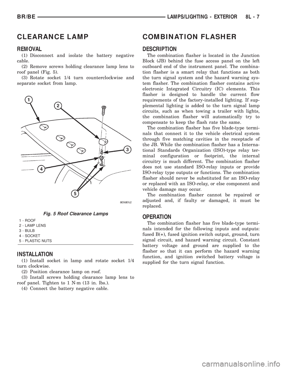
(2) Remove screws holding clearance lamp lens to
roof panel (Fig. 5).
(3) Rotate socket 1/4 turn counterclockwise and
separate socket from lamp.
INSTALLATION
(1) Install socket in lamp and rotate socket 1/4
turn clockwise.
(2) Position clearance lamp on roof.
(3) Install screws holding clearance lamp lens to
roof panel. Tighten to 1 N´m (13 in. lbs.).
(4) Connect the battery negative cable.
COMBINATION FLASHER
DESCRIPTION
The combination flasher is located in the Junction
Block (JB) behind the fuse access panel on the left
outboard end of the instrument panel. The combina-
tion flasher is a smart relay that functions as both
the turn signal system and the hazard warning sys-
tem flasher. The combination flasher contains active
electronic Integrated Circuitry (IC) elements. This
flasher is designed to handle the current flow
requirements of the factory-installed lighting. If sup-
plemental lighting is added to the turn signal lamp
circuits, such as when towing a trailer with lights,
the combination flasher will automatically try to
compensate to keep the flash rate the same.
The combination flasher has five blade-type termi-
nals that connect it to the vehicle electrical system
through five matching cavities in the receptacle of
the JB. While the combination flasher has a Interna-
tional Standards Organization (ISO)-type relay ter-
minal configuration or footprint, the internal
circuitry is much different. The combination flasher
does not use standard ISO-relay inputs or provide
ISO-relay type outputs or functions. The combination
flasher should never be substituted for an ISO-relay
or replaced with an ISO-relay, or else component and
vehicle damage may occur.
The combination flasher cannot be repaired or
adjusted and, if faulty or damaged, it must be
replaced.
OPERATION
The combination flasher has five blade-type termi-
nals intended for the following inputs and outputs:
fused B(+), fused ignition switch output, ground, turn
signal circuit, and hazard warning circuit. Constant
battery voltage and ground are supplied to the
flasher so that it can perform the hazard warning
function, and ignition switched battery voltage is
supplied for the turn signal function.
Fig. 5 Roof Clearance Lamps
1 - ROOF
2 - LAMP LENS
3 - BULB
4 - SOCKET
5 - PLASTIC NUTS
BR/BELAMPS/LIGHTING - EXTERIOR 8L - 7
Page 535 of 2255
(4) Pull the headlamp switch away from the
instrument panel far enough to access the instru-
ment panel wire harness connectors.
(5) Disconnect the two instrument panel wire har-
ness connectors for the headlamp switch from the
connector receptacles on the back of the switch.
(6) Remove the headlamp switch from the instru-
ment panel.
INSTALLATION
WARNING: ON VEHICLES EQUIPPED WITH AIR-
BAGS, DISABLE THE AIRBAG SYSTEM BEFORE
ATTEMPTING ANY STEERING WHEEL, STEERING
COLUMN, OR INSTRUMENT PANEL COMPONENT
DIAGNOSIS OR SERVICE. DISCONNECT AND ISO-
LATE THE BATTERY NEGATIVE (GROUND) CABLE,
THEN WAIT TWO MINUTES FOR THE AIRBAG SYS-
TEM CAPACITOR TO DISCHARGE BEFORE PER-
FORMING FURTHER DIAGNOSIS OR SERVICE. THIS
IS THE ONLY SURE WAY TO DISABLE THE AIRBAG
SYSTEM. FAILURE TO TAKE THE PROPER PRE-
CAUTIONS COULD RESULT IN ACCIDENTAL AIR-
BAG DEPLOYMENT AND POSSIBLE PERSONAL
INJURY.
(1) Position the headlamp switch to the instru-
ment panel.
(2) Reconnect the two instrument panel wire har-
ness connectors for the headlamp switch to the con-
nector receptacles on the back of the switch.
(3) Position the headlamp switch into the instru-
ment panel.
(4) Install and tighten the three screws that secure
the headlamp switch to the instrument panel.
Tighten the screws to 2.2 N´m (20 in. lbs.).
(5) Reinstall the cluster bezel onto the instrument
panel. (Refer to 23 - BODY/INSTRUMENT PANEL/
CLUSTER BEZEL - INSTALLATION).
(6) Connect the battery negative cable.
HEADLAMP UNIT
REMOVAL
(1) Disconnect and isolate the battery negative
cable.
(2) Remove push-in fastener attaching seal to radi-
ator closure panel.
(3) Remove park and turn signal lamp.
(4) Remove screws attaching top of headlamp mod-
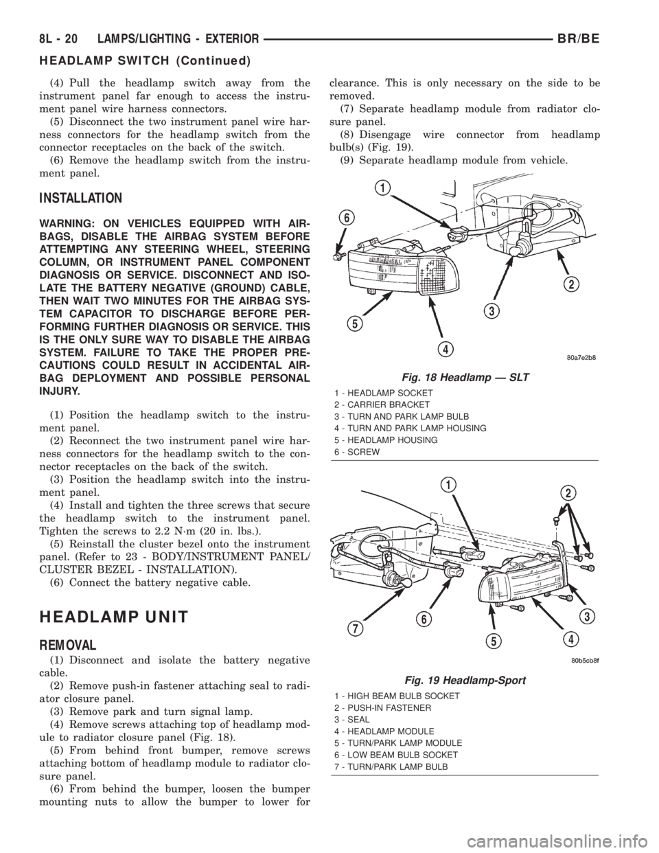
ule to radiator closure panel (Fig. 18).
(5) From behind front bumper, remove screws
attaching bottom of headlamp module to radiator clo-
sure panel.
(6) From behind the bumper, loosen the bumper
mounting nuts to allow the bumper to lower forclearance. This is only necessary on the side to be
removed.
(7) Separate headlamp module from radiator clo-
sure panel.
(8) Disengage wire connector from headlamp
bulb(s) (Fig. 19).
(9) Separate headlamp module from vehicle.
Fig. 18 Headlamp Ð SLT
1 - HEADLAMP SOCKET
2 - CARRIER BRACKET
3 - TURN AND PARK LAMP BULB
4 - TURN AND PARK LAMP HOUSING
5 - HEADLAMP HOUSING
6 - SCREW
Fig. 19 Headlamp-Sport
1 - HIGH BEAM BULB SOCKET
2 - PUSH-IN FASTENER
3 - SEAL
4 - HEADLAMP MODULE
5 - TURN/PARK LAMP MODULE
6 - LOW BEAM BULB SOCKET
7 - TURN/PARK LAMP BULB
8L - 20 LAMPS/LIGHTING - EXTERIORBR/BE
HEADLAMP SWITCH (Continued)
Page 730 of 2255
8W-15 GROUND DISTRIBUTION
Component Page
A/C Compressor Clutch.................8W-15-8, 10
A/C Heater Temperature Select.............8W-15-12
A/C-Heater Control.....................8W-15-14
Aftermarket Trailer Tow Connector............8W-15-6
Airbag Control Module....................8W-15-5
Ash Receiver Lamp.....................8W-15-14
Automatic Day/Night Mirror...............8W-15-13
Auxiliary Battery.......................8W-15-11
Battery.............................8W-15-11
Blend Door Actuator.....................8W-15-12
Blower Motor Relay......................8W-15-2
Brake Lamp Switch.....................8W-15-12
Brake Pressure Switch....................8W-15-3
Center High Mounted Stop Lamp No. 1........8W-15-17
Center High Mounted Stop Lamp No. 2........8W-15-17
Center Identification Lamp................8W-15-18
Central Timer Module.................8W-15-12, 13
Cigar Lighter.........................8W-15-14
Clockspring...........................8W-15-4
Combination Flasher....................8W-15-13
Controller Antilock Brake..................8W-15-5
Cummins Bus.........................8W-15-10
Cup Holder Lamp......................8W-15-14
Data Link Connector................8W-15-8, 10, 12
Daytime Running Lamp Module............8W-15-2, 3
Driver Cylinder Lock Switch...............8W-15-16
Driver Door Ajar Switch..................8W-15-16
Driver Door Window/Lock Switch..........8W-15-16, 17
Driver Heated Seat Cushion...............8W-15-15
Driver Heated Seat Switch................8W-15-13
Driver Power Seat Switch..............8W-15-15, 17
Electric Brake Provision..................8W-15-14
Engine Control Module....................8W-15-9
Engine Starter Motor Relay...............8W-15-8, 9
Fuel Heater..........................8W-15-10
Fuel Heater Relay.......................8W-15-2
Fuel Injection Pump.....................8W-15-9
Fuel Pump Module......................8W-15-7
Fuel Pump Relay.......................8W-15-2
Fuel Transfer Pump.....................8W-15-10
G100......................8W-15-2, 3, 4, 5, 7, 12
G101...............................8W-15-5
G102...............................8W-15-2
G105...............................8W-15-8
G107...............................8W-15-10
G113...............................8W-15-11
G114...............................8W-15-11
G115...............................8W-15-11
G116...............................8W-15-11
G117...............................8W-15-11
G118...............................8W-15-11
G120...............................8W-15-11
G200...........................8W-15-7, 12, 14
G201..........................8W-15-12, 13, 14
G300..........................8W-15-15, 16, 17
G301...............................8W-15-17
G302...............................8W-15-18
Glove Box Lamp And Switch...............8W-15-14
Headlamp Beam Select Switch..............8W-15-14
Headlamp Switch....................8W-15-13, 14
Heated Mirror Switch....................8W-15-13
High Note Horn........................8W-15-7
Ignition Switch........................8W-15-13
Instrument Cluster...................8W-15-12, 14
Component Page
Intake Air Heater Relay No. 1...............8W-15-9
Intake Air Heater Relay No. 2...............8W-15-9
Joint Connector No. 1...................8W-15-2, 5
Joint Connector No. 2....................8W-15-9
Joint Connector No. 5.................8W-15-13, 14
Joint Connector No. 6...................8W-15-4, 5
Joint Connector No. 8..................8W-15-5, 13
Junction Block...................8W-15-12, 13, 14
Left Back-Up Lamp......................8W-15-6
Left Front Door Speaker...................8W-15-4
Left Front Fender Lamp...................8W-15-6
Left License Lamp.......................8W-15-6
Left Outboard Clearance Lamp.............8W-15-18
Left Outboard Identification Lamp...........8W-15-18
Left Park/Turn Signal Lamp................8W-15-3
Left Power Mirror......................8W-15-16
Left Rear Fender Lamp...................8W-15-6
Left Remote Radio Switch..................8W-15-4
Left Tail/Stop/Turn Signal Lamp.............8W-15-6
Left Visor/Vanity Lamp...................8W-15-13
Low Note Horn.........................8W-15-7
Overdrive Switch.......................8W-15-12
Overhead Console......................8W-15-12
Oxygen Sensor 1/2 Left Bank Down...........8W-15-8
Oxygen Sensor 1/2 Pre-Catalyst..............8W-15-8
Oxygen Sensor 1/3 Post-Catalyst.............8W-15-8
Oxygen Sensor 2/2 Right Bank Down..........8W-15-8
Passenger Airbag On/Off Switch..............8W-15-5
Passenger Cylinder Lock Switch.............8W-15-16
Passenger Door Ajar Switch................8W-15-16
Passenger Door Window/Lock Switch..........8W-15-16
Passenger Heated Seat Cushion.............8W-15-15
Passenger Heated Seat Switch..............8W-15-13
Passenger Power Seat Switch..............8W-15-15
Power Distribution Center.................8W-15-2
Power Mirror Switch....................8W-15-16
Power Outlet.........................8W-15-14
Powertrain Control Module..............8W-15-8, 10
Quad High Beam Relay...................8W-15-2
Radio...............................8W-15-5
Radio Choke Relay......................8W-15-4
Right Back-Up Lamp.....................8W-15-6
Right Front Door Speaker..................8W-15-4
Right Front Fender Lamp..................8W-15-6
Right License Lamp......................8W-15-6
Right Outboard Clearance Lamp............8W-15-18
Right Outboard Identification Lamp..........8W-15-18
Right Park/Turn Signal Lamp...............8W-15-7
Right Power Mirror.....................8W-15-16
Right Rear Fender Lamp..................8W-15-6
Right Remote Radio Switch.................8W-15-4
Right Tail/Stop/Turn Signal Lamp............8W-15-6
Right Visor/Vanity Lamp..................8W-15-13
Seat Belt Switch.....................8W-15-15, 17
Seat Heat Interface Module................8W-15-15
Security Relay.........................8W-15-2
Speed Control Servo.....................8W-15-3
Tailgate Lamp.........................8W-15-6
Trailer Tow Connector....................8W-15-6
Trailer Tow Relay.......................8W-15-2
Underhood Lamp.......................8W-15-3
Washer Fluid Level Switch.................8W-15-3
Windshield Washer Pump..................8W-15-7
Wiper Motor...........................8W-15-7
BR/BE8W-15 GROUND DISTRIBUTION 8W - 15 - 1
Page 993 of 2255
LEFT FRONT WHEEL SPEED SENSOR (ABS)-2WAY
CAV CIRCUIT FUNCTION
1 B8 20RD/GY LEFT FRONT WHEEL SPEED SENSOR (-)
2 B9 20RD LEFT FRONT WHEEL SPEED SENSOR (+)
LEFT HEADLAMP - BLUE 3 WAY
CAV CIRCUIT FUNCTION
C L33 18LG/BR HIGH BEAM HEADLAMP DRIVER
B- -
A L45 18PK/RD FUSED B(+)
LEFT LICENSE LAMP - BLACK 2 WAY
CAV CIRCUIT FUNCTION
1 L7 18BK/YL HEADLAMP SWITCH OUTPUT
2 Z13 18BK GROUND
LEFT OUTBOARD CLEARANCE LAMP-2WAY
CAV CIRCUIT FUNCTION
1 L7 18BK/YL HEADLAMP SWITCH OUTPUT
2 Z4 18BK GROUND
LEFT OUTBOARD HEADLAMP - BLUE 3 WAY
CAV CIRCUIT FUNCTION
A L43 18VT FUSED B(+)
B L43 18VT (QUAD HEADLAMP) FUSED B(+)
A L4 20VT/WT (QUAD HEADLAMP) DIMMER SWITCH LOW BEAM OUTPUT
B L4 20VT/WT DIMMER SWITCH LOW BEAM OUTPUT
C L3 20RD/OR DIMMER SWITCH HIGH BEAM OUTPUT
8W - 80 - 58 8W-80 CONNECTOR PIN-OUTSBR/BE
Page 1011 of 2255
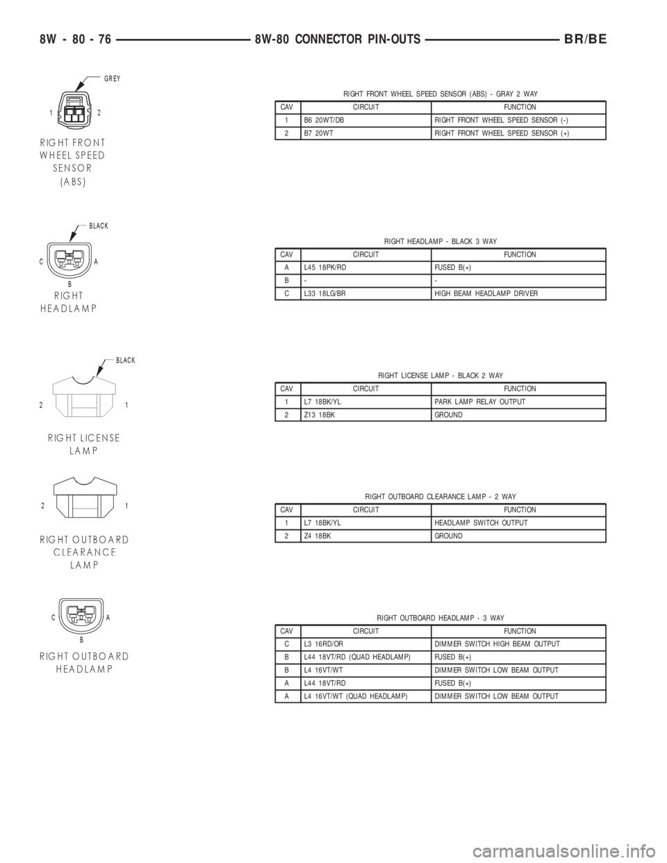
RIGHT FRONT WHEEL SPEED SENSOR (ABS) - GRAY 2 WAY
CAV CIRCUIT FUNCTION
1 B6 20WT/DB RIGHT FRONT WHEEL SPEED SENSOR (-)
2 B7 20WT RIGHT FRONT WHEEL SPEED SENSOR (+)
RIGHT HEADLAMP - BLACK 3 WAY
CAV CIRCUIT FUNCTION
A L45 18PK/RD FUSED B(+)
B- -
C L33 18LG/BR HIGH BEAM HEADLAMP DRIVER
RIGHT LICENSE LAMP - BLACK 2 WAY
CAV CIRCUIT FUNCTION
1 L7 18BK/YL PARK LAMP RELAY OUTPUT
2 Z13 18BK GROUND
RIGHT OUTBOARD CLEARANCE LAMP-2WAY
CAV CIRCUIT FUNCTION
1 L7 18BK/YL HEADLAMP SWITCH OUTPUT
2 Z4 18BK GROUND
RIGHT OUTBOARD HEADLAMP-3WAY
CAV CIRCUIT FUNCTION
C L3 16RD/OR DIMMER SWITCH HIGH BEAM OUTPUT
B L44 18VT/RD (QUAD HEADLAMP) FUSED B(+)
B L4 16VT/WT DIMMER SWITCH LOW BEAM OUTPUT
A L44 18VT/RD FUSED B(+)
A L4 16VT/WT (QUAD HEADLAMP) DIMMER SWITCH LOW BEAM OUTPUT
8W - 80 - 76 8W-80 CONNECTOR PIN-OUTSBR/BE
Page 1022 of 2255
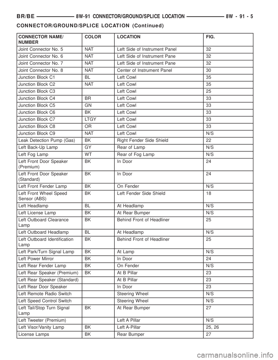
CONNECTOR NAME/
NUMBERCOLOR LOCATION FIG.
Joint Connector No. 5 NAT Left Side of Instrument Panel 32
Joint Connector No. 6 NAT Left Side of Instrument Pane 32
Joint Connector No. 7 NAT Left Side of Instrument Pane 32
Joint Connector No. 8 NAT Center of Instrument Panel 30
Junction Block C1 BL Left Cowl 35
Junction Block C2 NAT Left Cowl 35
Junction Block C3 Left Cowl 25
Junction Block C4 BR Left Cowl 33
Junction Block C5 GN Left Cowl 33
Junction Block C6 BK Left Cowl 33
Junction Block C7 LTGY Left Cowl 33
Junction Block C8 OR Left Cowl 33
Junction Block C9 NAT Left Cowl N/S
Leak Detection Pump (Gas) BK Right Fender Side Shield 22
Left Back-Up Lamp GY Rear of Lamp N/S
Left Fog Lamp WT Rear of Fog Lamp N/S
Left Front Door Speaker
(Premium)BK In Door 24
Left Front Door Speaker
(Standard)BK In Door 24
Left Front Fender Lamp BK On Fender N/S
Left Front Wheel Speed
Sensor (ABS)BK Left Fender Side Shield 18
Left Headlamp BL At Headlamp N/S
Left License Lamp BK At Rear Bumper N/S
Left Outboard Clearance
LampBK Behind Front of Headliner 25
Left Outboard Headlamp BL At Headlamp N/S
Left Outboard Identification
LampBK Behind Front of Headliner 25
Left Park/Turn Signal Lamp BK At Lamp N/S
Left Power Mirror BK In Door 24
Left Rear Fender Lamp BK On Fender N/S
Left Rear Speaker (Premium) BK At B Pillar 23
Left Rear Speaker (Standard) At B Pillar 23
Left Rear Door Speaker In Door 23
Left Remote Radio Switch Steering Wheel N/S
Left Speed Control Switch Steering Wheel N/S
Left Tail/Stop Turn Signal
LampBK At Rear Bumper 27
Left Tweeter (Premium) Left A Pillar N/S
Left Visor/Vanity Lamp BK Left A-Pillar 25, 26
License Lamps BK Rear Bumper 27
BR/BE8W-91 CONNECTOR/GROUND/SPLICE LOCATION 8W - 91 - 5
CONNECTOR/GROUND/SPLICE LOCATION (Continued)