2002 DODGE RAM lug pattern
[x] Cancel search: lug patternPage 95 of 2255

(10) Apply a bead of red Mopar Silicone Rubber
Sealant or equivalent to the housing cover (Fig. 44).
CAUTION: If housing cover is not installed within 3
to 5 minutes, the cover must be cleaned and new
RTV applied or adhesion quality will be compro-
mised.
(11) Install the cover and tighten bolts in a criss-
cross pattern to 47 N´m (35 ft. lbs.).
(12) Fill the differential with Mopar Hypoid Gear
Lubricant or equivalent to bottom of the fill plug
hole.
(13) Install fill hole plug and tighten to 34 N´m (25
ft. lbs.).
(14) Remove support and lower vehicle.DIFFERENTIAL CASE
BEARINGS
REMOVAL
(1) Remove differential case from axle housing.
(2) Remove bearings from the differential case
with Puller/Press C-293-PA, Adapters C-293-62 and
Step Plate C-4487-1 (Fig. 45).
Fig. 44 DIFFERENTIAL COVER - TYPICAL
1 - SEALANT SURFACE
2 - SEALANT
3 - SEALANT THICKNESS
Fig. 45 Differential Bearing Removal
1 - PULLER
2 - ADAPTERS
3 - STEP PLATE
4 - BEARING
5 - DIFFERENTIAL CASE
3 - 40 FRONT AXLE - 248FBIBR/BE
DIFFERENTIAL (Continued)
Page 122 of 2255

CAUTION: If housing cover is not installed within 3
to 5 minutes, the cover must be cleaned and new
RTV applied or adhesion quality will be compro-
mised.
(11) Install the cover and tighten bolts in a criss-
cross pattern to 47 N´m (35 ft. lbs.).
(12) Fill the differential with Mopar Hypoid Gear
Lubricant or equivalent to bottom of the fill plug
hole.(13) Install fill hole plug and tighten to 34 N´m (25
ft. lbs.).
(14) Remove support and lower vehicle.
DIFFERENTIAL - TRAC-LOK
DIAGNOSIS AND TESTING - TRAC-LOKT
The most common problem is a chatter noise when
turning corners. Before removing the unit for repair,
drain, flush and refill the axle with the specified
lubricant. A container of Mopar Trac-loktLubricant
(friction modifier) should be added after repair ser-
vice or during a lubricant change.
After changing the lubricant, drive the vehicle and
make 10 to 12 slow, figure-eight turns. This maneu-
ver will pump lubricant through the clutches. This
will correct the condition in most instances. If the
chatter persists, clutch damage could have occurred.
DIFFERENTIAL TEST
The differential can be tested without removing the
differential case by measuring rotating torque. Make
sure brakes are not dragging during this measure-
ment.
(1) Place blocks in front and rear of both front
wheels.
(2) Raise one rear wheel until it is completely off
the ground.
Fig. 33 DIFFERENTIAL CASE
1 - RAWHIDE HAMMER
Fig. 34 Bearing Cap Reference
1 - REFERENCE LETTERS
2 - REFERENCE LETTERS
Fig. 35 DIFFERENTIAL COVER - TYPICAL
1 - SEALANT SURFACE
2 - SEALANT
3 - SEALANT THICKNESS
BR/BEREAR AXLE - 248RBI 3 - 67
DIFFERENTIAL (Continued)
Page 153 of 2255

down clamps and tighten the tool turnbuckle finger-
tight.
(2) Install a Pilot Stud C-3288-B at the left side of
the differential housing and attach dial indicator to
the pilot stud. Load the indicator plunger against the
opposite side of the housing and zero the dial indica-
tor.
(3) Spread the housing enough to install the case
in the housing. Measure the distance with the dial
indicator.
CAUTION: Do not spread over 0.50 mm (0.020 in). If
the housing is over-spread, it could be distorted or
damaged.
(4) Remove the dial indicator.
(5) Install differential into the housing. Tap the
differential case with a rawhide/rubber hammer to
ensure the bearings are seated in housing (Fig. 33).
(6) Remove the spreader.
(7) Install bearing caps in their original locations
(Fig. 34) and tighten bearing cap bolts in a criss-
cross pattern to 109 N´m (80 ft. lbs.).
(8) Install axle shafts.
(9) Install the hub bearings.
(10) Apply a bead of red Mopar Silicone Rubber
Sealant or equivalent to the housing cover (Fig. 35).CAUTION: If housing cover is not installed within 3
to 5 minutes, the cover must be cleaned and new
RTV applied or adhesion quality will be compro-
mised.
(11) Install the cover and any identification tag.
Tighten the cover bolts in a criss-cross pattern to 47
N´m (35 ft. lbs.).
(12) Fill the differential with Mopar Hypoid Gear
Lubricant or equivalent to bottom of the fill plug
hole.
Fig. 32 Pinion Mate Shaft Roll-Pin
1 - PUNCH
2 - PINION MATE SHAFT
3 - MATE SHAFT LOCKPIN
Fig. 33 DIFFERENTIAL CASE
1 - RAWHIDE HAMMER
Fig. 34 BEARING CAP IDENTIFICATION
1 - REFERENCE LETTERS
2 - REFERENCE LETTERS
3 - 98 REAR AXLE - 267RBIBR/BE
DIFFERENTIAL (Continued)
Page 537 of 2255

VEHICLE PREPARATION FOR HEADLAMP
ALIGNMENT
(1) Verify headlamp dimmer switch and high beam
indicator operation.
(2) Verify headlamps are set for low beam opera-
tion.
(3) Correct defective components that could hinder
proper headlamp alignment.
(4) Verify proper tire inflation.
(5) Clean headlamp lenses.
(6) Verify that luggage area is not heavily loaded.
(7) Fuel tank should be FULL. Add 2.94 kg (6.5
lbs.) of weight over the fuel tank for each estimated
gallon of missing fuel.
HEADLAMP ADJUSTMENT
Headlamps can be aligned using the screen method
provided or alignment tool C-4466±A or equivalent
can be used. refer to the instructions provided with
the tool for proper procedures.
A properly aimed low beam headlamp will project
top edge of high intensity pattern on screen from 50
mm (2 in.) above to 50 mm (2 in.) below headlamp
centerline. The side-to-side outboard edge of high
intensity pattern should be from 50 mm (2 in.) left to
50 mm (2 in.) right of headlamp centerline. (Fig. 20)
The preferred headlamp alignment is 1º down
for the up/down adjustment and 0 for the left/
right adjustment.The high beam pattern should be
correct when the low beams are aligned properly.
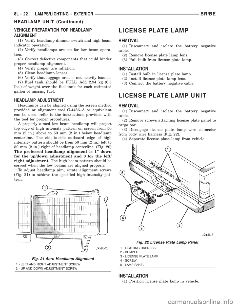
To adjust headlamp aim, rotate alignment screws
(Fig. 21) to achieve the specified high intensity pat-
tern.
LICENSE PLATE LAMP
REMOVAL
(1) Disconnect and isolate the battery negative
cable.
(2) Remove license plate lamp lens.
(3) Pull bulb from license plate lamp.
INSTALLATION
(1) Install bulb in license plate lamp.
(2) Install license plate lamp lens.
(3) Connect the battery negative cable.
LICENSE PLATE LAMP UNIT
REMOVAL
(1) Disconnect and isolate the battery negative
cable.
(2) Remove screws attaching license plate panel to
cargo box.
(3) Disengage license plate lamp wire connector
from body wire harness (Fig. 22).
(4) Separate license plate lamp from vehicle.
INSTALLATION
(1) Position license plate lamp in vehicle.
Fig. 21 Aero Headlamp Alignment
1 - LEFT AND RIGHT ADJUSTMENT SCREW
2 - UP AND DOWN ADJUSTMENT SCREW
Fig. 22 License Plate Lamp Panel
1 - LIGHTING HARNESS
2 - BUMPER
3 - LICENSE PLATE LAMP
4 - SCREW
5 - LAMP PANEL
8L - 22 LAMPS/LIGHTING - EXTERIORBR/BE
HEADLAMP UNIT (Continued)
Page 649 of 2255

(CTM) from the CTM connector receptacle. Reconnect
the battery negative cable. Turn the ignition switch
to the On position. With the washer button
depressed, check for battery voltage at the washer
switch sense circuit cavity of the instrument panel
wire harness connector (Connector C1) for the CTM.
If OK, proceed to the diagnosis for the wiper relay.
(Refer to 8 - ELECTRICAL/WIPERS/WASHERS/
WIPER RELAY - DIAGNOSIS AND TESTING). If
not OK, repair the open washer switch sense circuit
between the CTM and the multi-function switch as
required.
CLEANING - WIPER & WASHER SYSTEM
WIPER SYSTEM
The squeegees of wiper blades exposed to the ele-
ments for a long time tend to lose their wiping effec-
tiveness. Periodic cleaning of the squeegees is
suggested to remove any deposits of salt or road film.
The wiper blades, arms, and windshield glass should
only be cleaned using a sponge or soft cloth and
windshield washer fluid, a mild detergent, or a non-
abrasive cleaner. If the wiper blades continue to
leave streaks, smears, hazing, or beading on the
glass after thorough cleaning of the squeegees and
the glass, the entire wiper blade assembly must be
replaced.
CAUTION: Protect the rubber squeegees of the
wiper blades from any petroleum-based cleaners,
solvents, or contaminants. These products can rap-
idly deteriorate the rubber squeegees.
WASHER SYSTEM
If the washer system is contaminated with foreign
material, drain the washer reservoir by removing the
front washer pump/motor from the reservoir. Clean
foreign material from the inside of the washer reser-
voir using clean washer fluid, a mild detergent, or a
non-abrasive cleaner. Flush foreign material from the
washer system plumbing by first disconnecting the
washer hoses from the washer nozzles, then running
the washer pump/motor to run clean washer fluid or
water through the system. Plugged or restricted
washer nozzles should be carefully back-flushed
using compressed air. If the washer nozzle obstruc-
tion cannot be cleared, replace the washer nozzle.
CAUTION: Never introduce petroleum-based clean-
ers, solvents, or contaminants into the washer sys-
tem. These products can rapidly deteriorate the
rubber seals and hoses of the washer system, as
well as the rubber squeegees of the wiper blades.CAUTION: Never use compressed air to flush the
washer system plumbing. Compressed air pres-
sures are too great for the washer system plumbing
components and will result in further system dam-
age. Never use sharp instruments to clear a
plugged washer nozzle or damage to the nozzle ori-
fice and improper nozzle spray patterns will result.
INSPECTION - WIPER & WASHER SYSTEM
WIPER SYSTEM
The wiper blades and wiper arms should be
inspected periodically, not just when wiper perfor-
mance problems are experienced. This inspection
should include the following points:
(1) Inspect the wiper arms for any indications of
damage, or contamination. If the wiper arms are con-
taminated with any foreign material, clean them as
required. (Refer to 8 - ELECTRICAL/WIPERS/
WASHERS - CLEANING). If a wiper arm is damaged
or corrosion is evident, replace the wiper arm with a
new unit. Do not attempt to repair a wiper arm that
is damaged or corroded.
(2) Carefully lift the wiper blade off of the glass.
Note the action of the wiper arm hinge. The wiper
arm should pivot freely at the hinge, but with no lat-
eral looseness evident. If there is any binding evident
in the wiper arm hinge, or there is evident lateral
play in the wiper arm hinge, replace the wiper arm.
CAUTION: Do not allow the wiper arm to spring
back against the glass without the wiper blade in
place or the glass may be damaged.
(3) Once proper hinge action of the wiper arm is
confirmed, check the hinge for proper spring tension.
Remove the wiper blade from the wiper arm. Either
place a small postal scale between the blade end of
the wiper arm and the glass, or carefully lift the
blade end of the arm away from the glass using a
small fish scale. Compare the scale readings between
the right and left wiper arms. Replace a wiper arm if
it has comparatively lower spring tension, as evi-
denced by a lower scale reading.
(4) Inspect the wiper blades and squeegees for any
indications of damage, contamination, or rubber dete-
rioration (Fig. 1). If the wiper blades or squeegees
are contaminated with any foreign material, clean
them and the glass as required. (Refer to 8 - ELEC-
TRICAL/WIPERS/WASHERS - CLEANING). After
cleaning the wiper blade and the glass, if the wiper
blade still fails to clear the glass without smearing,
streaking, chattering, hazing, or beading, replace the
wiper blade. Also, if a wiper blade is damaged or the
squeegee rubber is damaged or deteriorated, replace
8R - 6 WIPERS/WASHERSBR/BE
WIPERS/WASHERS (Continued)
Page 1072 of 2255

HEADLAMP RELAY
DESCRIPTION
The headlamp (or security) relay is a International
Standards Organization (ISO) micro-relay. The termi-
nal designations and functions are the same as a con-
ventional ISO relay. However, the micro-relay
terminal orientation (or footprint) is different, cur-
rent capacity is lower, and the relay case dimensions
are smaller than those of the conventional ISO relay.
The headlamp relay is a electromechanical device
that switches battery current to the headlamps when
the high-line or premium Central Timer Module
(CTM) grounds the relay coil. See Headlamp Relay in
the Diagnosis and Testing section of this group for
more information.
The headlamp (or security) relay is located in the
Power Distribution Center (PDC), in the engine com-
partment. Refer to the PDC label for relay identifica-
tion and location.
The headlamp relay cannot be repaired and, if
faulty or damaged, it must be replaced.
REMOVAL
(1) Disconnect and isolate the battery negative
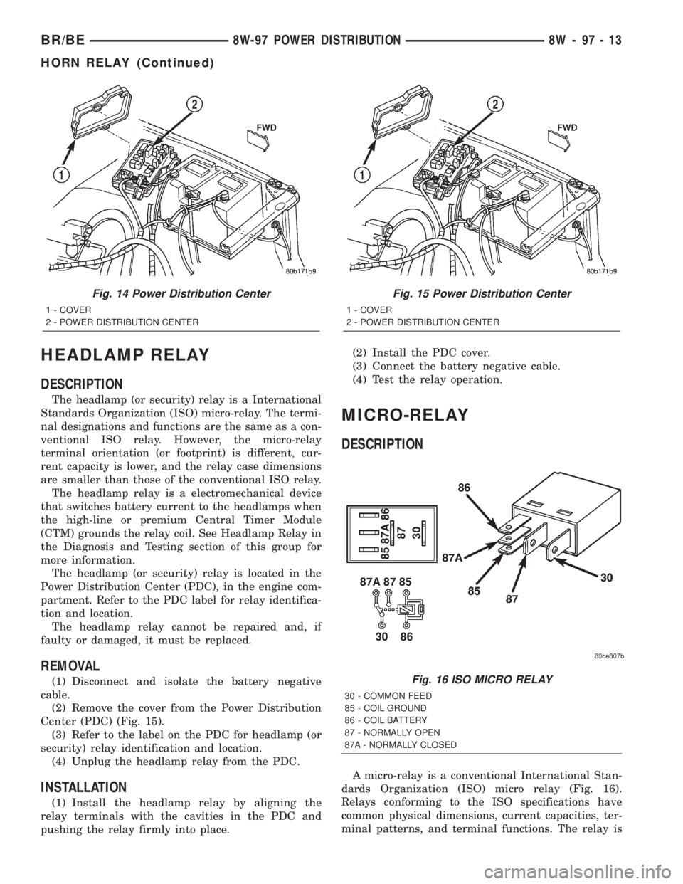
cable.
(2) Remove the cover from the Power Distribution
Center (PDC) (Fig. 15).
(3) Refer to the label on the PDC for headlamp (or
security) relay identification and location.
(4) Unplug the headlamp relay from the PDC.
INSTALLATION
(1) Install the headlamp relay by aligning the
relay terminals with the cavities in the PDC and
pushing the relay firmly into place.(2) Install the PDC cover.
(3) Connect the battery negative cable.
(4) Test the relay operation.
MICRO-RELAY
DESCRIPTION
A micro-relay is a conventional International Stan-
dards Organization (ISO) micro relay (Fig. 16).
Relays conforming to the ISO specifications have
common physical dimensions, current capacities, ter-
minal patterns, and terminal functions. The relay is
Fig. 14 Power Distribution Center
1 - COVER
2 - POWER DISTRIBUTION CENTER
Fig. 15 Power Distribution Center
1 - COVER
2 - POWER DISTRIBUTION CENTER
Fig. 16 ISO MICRO RELAY
30 - COMMON FEED
85 - COIL GROUND
86 - COIL BATTERY
87 - NORMALLY OPEN
87A - NORMALLY CLOSED
BR/BE8W-97 POWER DISTRIBUTION 8W - 97 - 13
HORN RELAY (Continued)
Page 1086 of 2255

mounting holes must be circled. For corner sealing, a
3.17 or 6.35 mm (1/8 or 1/4 in.) drop is placed in the
center of the gasket contact area. Uncured sealant
may be removed with a shop towel. Components
should be torqued in place while the sealant is still
wet to the touch (within 10 minutes). The usage of a
locating dowel is recommended during assembly to
prevent smearing material off the location.
MopartGasket Sealant in an aerosol can should be
applied using a thin, even coat sprayed completely
over both surfaces to be joined, and both sides of a
gasket. Then proceed with assembly. Material in a
can w/applicator can be brushed on evenly over the
sealing surfaces. Material in an aerosol can should be
used on engines with multi-layer steel gaskets.
STANDARD PROCEDURE - REPAIR DAMAGED
OR WORN THREADS
CAUTION: Be sure that the tapped holes maintain
the original center line.
Damaged or worn threads can be repaired. Essen-
tially, this repair consists of:
²Drilling out worn or damaged threads.
²Tapping the hole with a special Heli-Coil Tap, or
equivalent.
²Installing an insert into the tapped hole to bring
the hole back to its original thread size.
STANDARD PROCEDUREÐHYDROSTATIC
LOCK
CAUTION: DO NOT use the starter motor to rotate
the crankshaft. Severe damage could occur.
When an engine is suspected of hydrostatic lock
(regardless of what caused the problem), follow the
steps below.
(1) Perform the Fuel Pressure Release Procedure
(Refer to 14 - FUEL SYSTEM/FUEL DELIVERY -
STANDARD PROCEDURE).
(2) Disconnect the negative cable(s) from the bat-
tery.
(3) Inspect air cleaner, induction system, and
intake manifold to ensure system is dry and clear of
foreign material.
(4) Place a shop towel around the spark plugs to
catch any fluid that may possibly be under pressure
in the cylinder head. Remove the spark plugs.
(5) With all spark plugs removed, rotate the crank-
shaft using a breaker bar and socket.
(6) Identify the fluid in the cylinders (coolant, fuel,
oil, etc.).
(7) Be sure all fluid has been removed from the
cylinders.(8) Repair engine or components as necessary to
prevent this problem from occurring again.
(9) Squirt a small amount of engine oil into the
cylinders to lubricate the walls. This will prevent
damage on restart.
(10) Install new spark plugs. Tighten the spark
plugs to 41 N´m (30 ft. lbs.) torque.
(11) Drain engine oil. Remove and discard the oil
filter.
(12) Install the drain plug. Tighten the plug to 34
N´m (25 ft. lbs.) torque.
(13) Install a new oil filter.
(14) Fill engine crankcase with the specified
amount and grade of oil. (Refer to LUBRICATION &
MAINTENANCE - SPECIFICATIONS).
(15) Connect the negative cable(s) to the battery.
(16) Start the engine and check for any leaks.
STANDARD PROCEDURE - CYLINDER BORE
HONING
Before honing, stuff plenty of clean shop towels
under the bores and over the crankshaft to keep
abrasive materials from entering the crankshaft
area.
(1) Used carefully, the Cylinder Bore Sizing Hone
C-823, equipped with 220 grit stones, is the best tool
for this job. In addition to deglazing, it will reduce
taper and out-of-round, as well as removing light
scuffing, scoring and scratches. Usually, a few strokes
will clean up a bore and maintain the required lim-
its.
CAUTION: DO NOT use rigid type hones to remove
cylinder wall glaze.
(2) Deglazing of the cylinder walls may be done if
the cylinder bore is straight and round. Use a cylin-
der surfacing hone, Honing Tool C-3501, equipped
with 280 grit stones (C-3501-3810). about 20-60
strokes, depending on the bore condition, will be suf-
ficient to provide a satisfactory surface. Using honing
oil C-3501-3880, or a light honing oil, available from
major oil distributors.
CAUTION: DO NOT use engine or transmission oil,
mineral spirits, or kerosene.
(3) Honing should be done by moving the hone up
and down fast enough to get a crosshatch pattern.
The hone marks should INTERSECT at 40É to 60É
for proper seating of rings (Fig. 3).
(4) A controlled hone motor speed between 200 and
300 RPM is necessary to obtain the proper cross-
hatch angle. The number of up and down strokes per
minute can be regulated to get the desired 40É to 60É
angle. Faster up and down strokes increase the cross-
hatch angle.
BR/BEENGINE 5.9L 9 - 11
ENGINE 5.9L (Continued)
Page 1399 of 2255

(2) Note RPM drop for each cylinder. As an alter-
native, loosen high-pressure fuel line fitting at fuel
injector connector tube (Fig. 15). Listen for a change
in engine speed. After testing, tighten line fitting to
40 N´m (30 ft. lbs.) torque. If engine speed drops,
injector was operating normally. If engine speed
remains same, injector may be malfunctioning. Test
all injectors in same manner one at a time.(3) Once injector has been found to be malfunc-
tioning, remove it from engine and test it. Refer to
Fuel Injector Removal/Installation.
WARNING: FUEL INJECTOR TESTERS CAN
DEVELOP EXTREMELY HIGH PRESSURES. FUEL
UNDER THIS AMOUNT OF PRESSURE CAN PENE-
TRATE SKIN AND CAUSE PERSONAL INJURY.
WEAR SAFETY GOGGLES AND ADEQUATE PRO-
TECTIVE CLOTHING. AVOID CONTACT WITH FUEL
SPRAY WHEN OPERATING INJECTOR TESTOR.
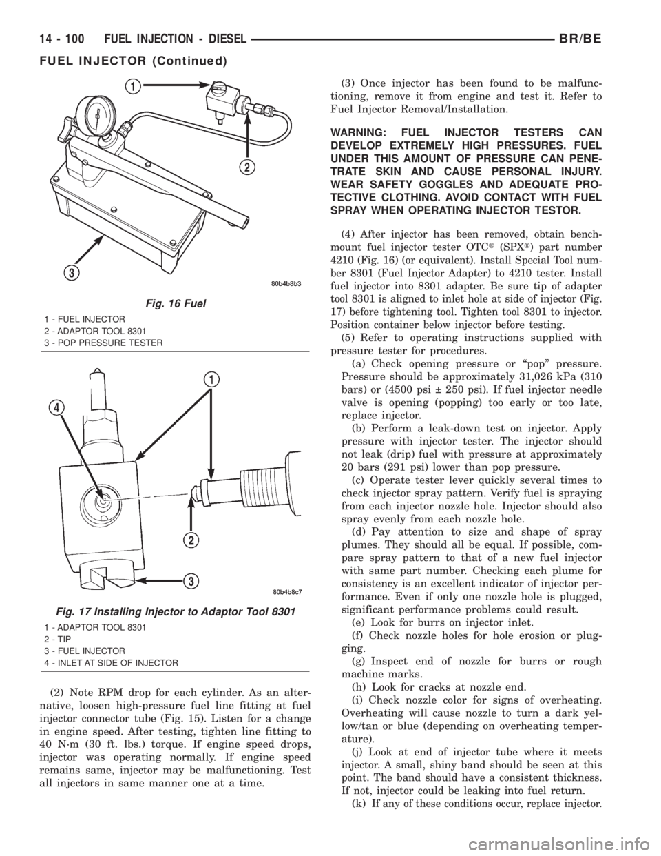
(4)
After injector has been removed, obtain bench-
mount fuel injector tester OTCt(SPXt) part number
4210 (Fig. 16) (or equivalent). Install Special Tool num-
ber 8301 (Fuel Injector Adapter) to 4210 tester. Install
fuel injector into 8301 adapter. Be sure tip of adapter
tool 8301 is aligned to inlet hole at side of injector (Fig.
17) before tightening tool. Tighten tool 8301 to injector.
Position container below injector before testing.
(5) Refer to operating instructions supplied with
pressure tester for procedures.
(a) Check opening pressure or ªpopº pressure.
Pressure should be approximately 31,026 kPa (310
bars) or (4500 psi 250 psi). If fuel injector needle
valve is opening (popping) too early or too late,
replace injector.
(b) Perform a leak-down test on injector. Apply
pressure with injector tester. The injector should
not leak (drip) fuel with pressure at approximately
20 bars (291 psi) lower than pop pressure.
(c) Operate tester lever quickly several times to
check injector spray pattern. Verify fuel is spraying
from each injector nozzle hole. Injector should also
spray evenly from each nozzle hole.
(d) Pay attention to size and shape of spray
plumes. They should all be equal. If possible, com-
pare spray pattern to that of a new fuel injector
with same part number. Checking each plume for
consistency is an excellent indicator of injector per-
formance. Even if only one nozzle hole is plugged,
significant performance problems could result.
(e) Look for burrs on injector inlet.
(f) Check nozzle holes for hole erosion or plug-
ging.
(g) Inspect end of nozzle for burrs or rough
machine marks.
(h) Look for cracks at nozzle end.
(i) Check nozzle color for signs of overheating.
Overheating will cause nozzle to turn a dark yel-
low/tan or blue (depending on overheating temper-
ature).
(j)
Look at end of injector tube where it meets
injector. A small, shiny band should be seen at this
point. The band should have a consistent thickness.
If not, injector could be leaking into fuel return.
(k)If any of these conditions occur, replace injector.
Fig. 16 Fuel
1 - FUEL INJECTOR
2 - ADAPTOR TOOL 8301
3 - POP PRESSURE TESTER
Fig. 17 Installing Injector to Adaptor Tool 8301
1 - ADAPTOR TOOL 8301
2 - TIP
3 - FUEL INJECTOR
4 - INLET AT SIDE OF INJECTOR
14 - 100 FUEL INJECTION - DIESELBR/BE
FUEL INJECTOR (Continued)