2002 DODGE RAM check oil
[x] Cancel search: check oilPage 19 of 2255

DESCRIPTION - AUTOMATIC TRANSMISSION
FLUID
NOTE: Refer to the maintenance schedules in this
group for the recommended maintenance (fluid/filter
change) intervals for this transmission.
NOTE: Refer to Service Procedures in this group for
fluid level checking procedures.
MopartATF +4, type 9602, Automatic Transmis-
sion Fluid is the recommended fluid for
DaimlerChrysler automatic transmissions.
Dexron II fluid IS NOT recommended. Clutch
chatter can result from the use of improper
fluid.
MopartATF +4, type 9602, Automatic Transmis-
sion Fluid when new is red in color. The ATF is dyed
red so it can be identified from other fluids used in
the vehicle such as engine oil or antifreeze. The red
color is not permanent and is not an indicator of fluid
condition. As the vehicle is driven, the ATF will begin
to look darker in color and may eventually become
brown.This is normal.A dark brown/black fluid
accompanied with a burnt odor and/or deterioration
in shift quality may indicate fluid deterioration or
transmission component failure.
FLUID ADDITIVES
DaimlerChrysler strongly recommends against the
addition of any fluids to the transmission, other than
those automatic transmission fluids listed above.
Exceptions to this policy are the use of special dyes
to aid in detecting fluid leaks.
Various ªspecialº additives and supplements exist
that claim to improve shift feel and/or quality. These
additives and others also claim to improve converter
clutch operation and inhibit overheating, oxidation,
varnish, and sludge. These claims have not been sup-
ported to the satisfaction of DaimlerChrysler and
these additivesmust not be used.The use of trans-
mission ªsealersº should also be avoided, since they
may adversely affect the integrity of transmission
seals.
OPERATION - AUTOMATIC TRANSMISSION
FLUID
The automatic transmission fluid is selected based
upon several qualities. The fluid must provide a high
level of protection for the internal components by
providing a lubricating film between adjacent metal
components. The fluid must also be thermally stable
so that it can maintain a consistent viscosity through
a large temperature range. If the viscosity stays con-
stant through the temperature range of operation,transmission operation and shift feel will remain con-
sistent. Transmission fluid must also be a good con-
ductor of heat. The fluid must absorb heat from the
internal transmission components and transfer that
heat to the transmission case.
FLUID CAPACITIES
SPECIFICATIONS
FLUID CAPACITIES
DESCRIPTION SPECIFICATION
FUEL TANK
2500 Series Club Cab
and Quad Cab with 6.5'
Short Box129 L (34 gal.)*****
All 8' Long Box 132 L (35 gal.)*****
All Cab/Chassis Models 132 L (35 gal.)*****
ENGINE OIL WITH FILTER
5.9L 4.7 L (5.0 qts.)
8.0L 6.6 L (7.0 qts.)
5.9L DIESEL 10.4 L (11.0 qts.)
COOLING SYSTEM
5.9L 19 L (20 qts.)****
8.0L 24.5 L (26.0 qts.)****
5.9L DIESEL 22.7 L (24.0 qts.)****
POWER STEERING
Power steering fluid capacities are dependent on
engine/chassis options as well as steering gear/cooler
options. Depending on type and size of internal
cooler, length and inside diameter of cooler lines, or
use of an auxiliary cooler, these capacities may vary.
Refer to 19, Steering for proper fill and bleed
procedures.
AUTOMATIC TRANSMISSION
Service Fill - 46RE 3.8 L (4.0 qts.)
O-haul - 46RE 9-9.5L (19-20 pts.)*
Service Fill - 47RE 3.8 L (4.0 qts.)
O-haul - 47RE 14-16 L (29-33 pts.)*
0 - 6 LUBRICATION & MAINTENANCEBR/BE
FLUID TYPES (Continued)
Page 30 of 2255
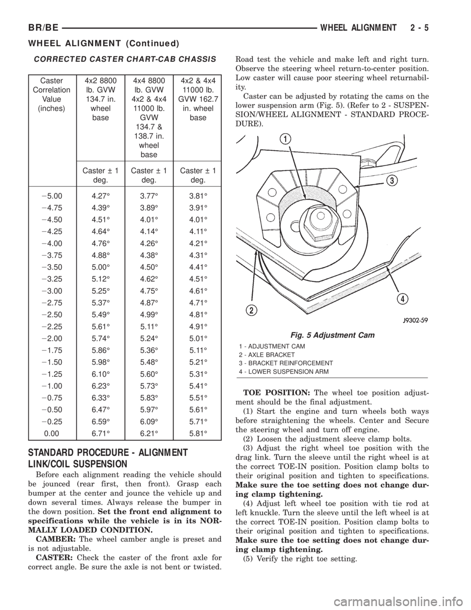
CORRECTED CASTER CHART-CAB CHASSIS
Caster
Correlation
Value
(inches)4x2 8800
lb. GVW
134.7 in.
wheel
base4x4 8800
lb. GVW
4x2 & 4x4
11000 lb.
GVW
134.7 &
138.7 in.
wheel
base4x2 & 4x4
11000 lb.
GVW 162.7
in. wheel
base
Caster 1
deg.Caster 1
deg.Caster 1
deg.
25.00 4.27É 3.77É 3.81É
24.75 4.39É 3.89É 3.91É
24.50 4.51É 4.01É 4.01É
24.25 4.64É 4.14É 4.11É
24.00 4.76É 4.26É 4.21É
23.75 4.88É 4.38É 4.31É
23.50 5.00É 4.50É 4.41É
23.25 5.12É 4.62É 4.51É
23.00 5.25É 4.75É 4.61É
22.75 5.37É 4.87É 4.71É
22.50 5.49É 4.99É 4.81É
22.25 5.61É 5.11É 4.91É
22.00 5.74É 5.24É 5.01É
21.75 5.86É 5.36É 5.11É
21.50 5.98É 5.48É 5.21É
21.25 6.10É 5.60É 5.31É
21.00 6.23É 5.73É 5.41É
20.75 6.33É 5.83É 5.51É
20.50 6.47É 5.97É 5.61É
20.25 6.59É 6.09É 5.71É
0.00 6.71É 6.21É 5.81É
STANDARD PROCEDURE - ALIGNMENT
LINK/COIL SUSPENSION
Before each alignment reading the vehicle should
be jounced (rear first, then front). Grasp each
bumper at the center and jounce the vehicle up and
down several times. Always release the bumper in
the down position.Set the front end alignment to
specifications while the vehicle is in its NOR-
MALLY LOADED CONDITION.
CAMBER:The wheel camber angle is preset and
is not adjustable.
CASTER:Check the caster of the front axle for
correct angle. Be sure the axle is not bent or twisted.Road test the vehicle and make left and right turn.
Observe the steering wheel return-to-center position.
Low caster will cause poor steering wheel returnabil-
ity.
Caster can be adjusted by rotating the cams on the
lower suspension arm (Fig. 5). (Refer to 2 - SUSPEN-
SION/WHEEL ALIGNMENT - STANDARD PROCE-
DURE).
TOE POSITION:The wheel toe position adjust-
ment should be the final adjustment.
(1) Start the engine and turn wheels both ways
before straightening the wheels. Center and Secure
the steering wheel and turn off engine.
(2) Loosen the adjustment sleeve clamp bolts.
(3) Adjust the right wheel toe position with the
drag link. Turn the sleeve until the right wheel is at
the correct TOE-IN position. Position clamp bolts to
their original position and tighten to specifications.
Make sure the toe setting does not change dur-
ing clamp tightening.
(4) Adjust left wheel toe position with tie rod at
left knuckle. Turn the sleeve until the left wheel is at
the correct TOE-IN position. Position clamp bolts to
their original position and tighten to specifications.
Make sure the toe setting does not change dur-
ing clamp tightening.
(5) Verify the right toe setting.
Fig. 5 Adjustment Cam
1 - ADJUSTMENT CAM
2 - AXLE BRACKET
3 - BRACKET REINFORCEMENT
4 - LOWER SUSPENSION ARM
BR/BEWHEEL ALIGNMENT 2 - 5
WHEEL ALIGNMENT (Continued)
Page 36 of 2255

²136 N´m (110 ft. lbs.) Install the lower ball joint
cotter pin.
(6) Install the stabilizer bar link on the lower sus-
pension arm. Install the grommet, retainer and nut
and tighten to 37 N´m (27 ft. lbs.).
(7) Install the tie rod end on the steering knuckle
and tighten nut to 108 N´m (80 ft. lbs.). Install cotter
pin.
(8) Install the brake rotor and caliper assembly,
(Refer to 5 - BRAKES/HYDRAULIC/MECHANICAL/
ROTORS - INSTALLATION).
(9) Install the tire and wheel assembly, (Refer to
22 - TIRES/WHEELS/WHEELS - STANDARD PRO-
CEDURE).
(10) Remove the support and lower the vehicle.
(11) Tighten the suspension arm crossmember
nuts to 169 N´m (125 ft. lbs.).
SHOCK
DIAGNOSIS AND TESTING - SHOCK
A knocking or rattling noise from a shock absorber
may be caused by movement between mounting
bushings and metal brackets or attaching compo-
nents. These noises can usually be stopped by tight-
ening the attaching nuts. If the noise persists,
inspect for damaged and worn bushings, and attach-
ing components. Repair as necessary if any of these
conditions exist.
A squeaking noise from the shock absorber may be
caused by the hydraulic valving and may be intermit-
tent. This condition is not repairable and the shock
absorber must be replaced.
The shock absorbers are not refillable or adjust-
able. If a malfunction occurs, the shock absorber
must be replaced. To test a shock absorber, hold it in
an upright position and force the piston in and out of
the cylinder four or five times. The action throughout
each stroke should be smooth and even.
The shock absorber bushings do not require any
type of lubrication. Do not attempt to stop bushing
noise by lubricating them. Grease and mineral oil-
base lubricants will deteriorate the bushing.
REMOVAL
(1) Raise and support vehicle.
(2) Remove shock upper nut and remove retainer
and grommet.
(3) Remove lower mounting bolt from suspension
arm and remove shock (Fig. 5).
INSTALLATION
(1) Extend shock fully, install retainer and grom-
met on top of shock absorber. Check grommets and
retainer for wear.(2) Guide shock up through upper suspension arm
bracket. Install top grommet, retainer and nut.
Tighten nut to 54 N´m (40 ft. lbs.).
(3) Align bottom end of shock into lower suspen-
sion arm and install mounting bolt. Tighten bolt to
142 N´m (105 ft. lbs.).
(4) Remove support and lower vehicle.
SPRING
REMOVAL
(1) Raise and support the vehicle.
(2) Remove the tire and wheel assembly.
(3) Remove the brake caliper assembly and rotor,
(Refer to 5 - BRAKES/HYDRAULIC/MECHANICAL/
ROTORS - REMOVAL).
(4) Remove the cotter pin and nut from the tie rod.
Remove the tie rod end from the steering knuckle
with Puller C-3894-A.
(5) Remove the stabilizer bar link from the lower
suspension arm.
(6) Support the lower suspension arm outboard
end with a jack. Place a jack under the arm in front
of the shock mount.
(7) Remove the cotter pin and nut from the lower
ball joint. Separate the ball joint with Remover
C-4150A.
(8) Remove the lower shock bolt from the suspen-
sion arm.
(9) Lower the jack and suspension arm until
spring tension is relieved. Remove spring and rubber
isolator (Fig. 6).
Fig. 5 Shock
1 - SHOCK
2 - JOUNCE BUMPER
BR/BEFRONT - 2WD 2 - 11
LOWER CONTROL ARM (Continued)
Page 50 of 2255
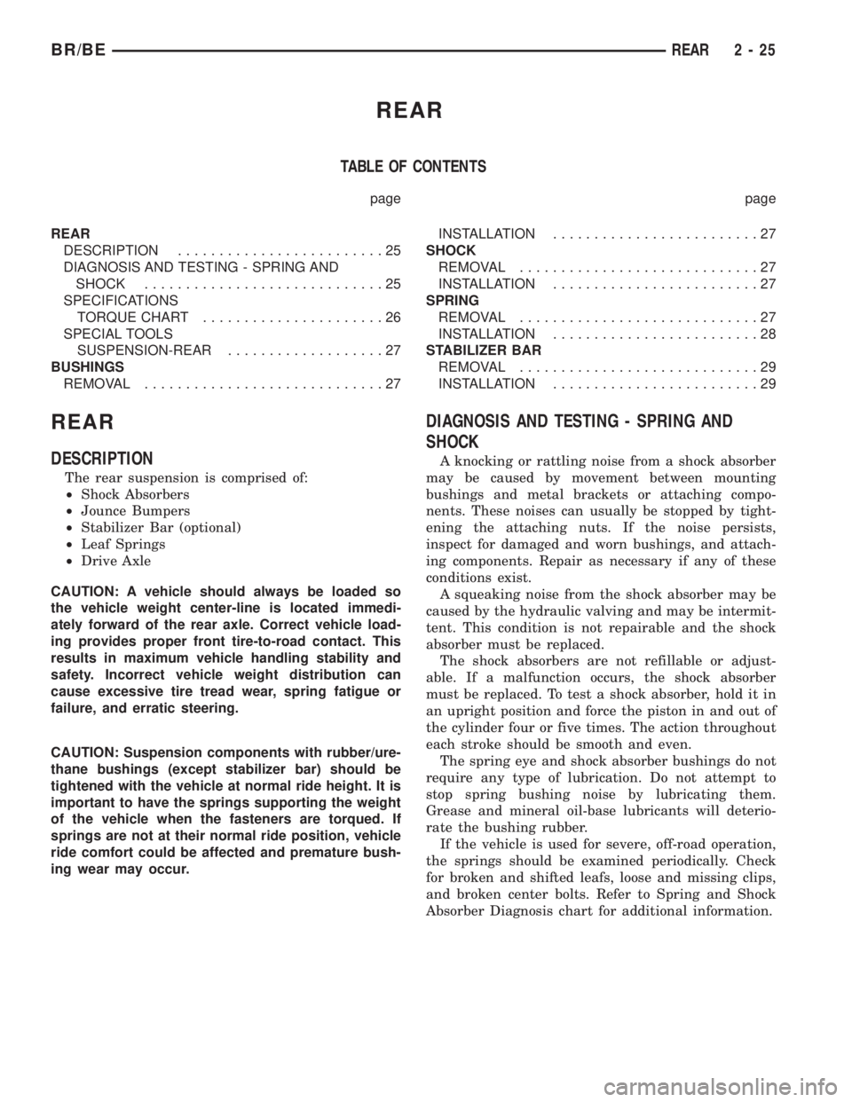
REAR
TABLE OF CONTENTS
page page
REAR
DESCRIPTION.........................25
DIAGNOSIS AND TESTING - SPRING AND
SHOCK.............................25
SPECIFICATIONS
TORQUE CHART......................26
SPECIAL TOOLS
SUSPENSION-REAR...................27
BUSHINGS
REMOVAL.............................27INSTALLATION.........................27
SHOCK
REMOVAL.............................27
INSTALLATION.........................27
SPRING
REMOVAL.............................27
INSTALLATION.........................28
STABILIZER BAR
REMOVAL.............................29
INSTALLATION.........................29
REAR
DESCRIPTION
The rear suspension is comprised of:
²Shock Absorbers
²Jounce Bumpers
²Stabilizer Bar (optional)
²Leaf Springs
²Drive Axle
CAUTION: A vehicle should always be loaded so
the vehicle weight center-line is located immedi-
ately forward of the rear axle. Correct vehicle load-
ing provides proper front tire-to-road contact. This
results in maximum vehicle handling stability and
safety. Incorrect vehicle weight distribution can
cause excessive tire tread wear, spring fatigue or
failure, and erratic steering.
CAUTION: Suspension components with rubber/ure-
thane bushings (except stabilizer bar) should be
tightened with the vehicle at normal ride height. It is
important to have the springs supporting the weight
of the vehicle when the fasteners are torqued. If
springs are not at their normal ride position, vehicle
ride comfort could be affected and premature bush-
ing wear may occur.
DIAGNOSIS AND TESTING - SPRING AND
SHOCK
A knocking or rattling noise from a shock absorber
may be caused by movement between mounting
bushings and metal brackets or attaching compo-
nents. These noises can usually be stopped by tight-
ening the attaching nuts. If the noise persists,
inspect for damaged and worn bushings, and attach-
ing components. Repair as necessary if any of these
conditions exist.
A squeaking noise from the shock absorber may be
caused by the hydraulic valving and may be intermit-
tent. This condition is not repairable and the shock
absorber must be replaced.
The shock absorbers are not refillable or adjust-
able. If a malfunction occurs, the shock absorber
must be replaced. To test a shock absorber, hold it in
an upright position and force the piston in and out of
the cylinder four or five times. The action throughout
each stroke should be smooth and even.
The spring eye and shock absorber bushings do not
require any type of lubrication. Do not attempt to
stop spring bushing noise by lubricating them.
Grease and mineral oil-base lubricants will deterio-
rate the bushing rubber.
If the vehicle is used for severe, off-road operation,
the springs should be examined periodically. Check
for broken and shifted leafs, loose and missing clips,
and broken center bolts. Refer to Spring and Shock
Absorber Diagnosis chart for additional information.
BR/BEREAR 2 - 25
Page 73 of 2255

Condition Possible Causes Correction
Gear Teeth Broke 1. Overloading. 1. Replace gears. Examine other
gears and bearings for possible
damage.
2. Erratic clutch operation. 2. Replace gears and examine the
remaining parts for damage. Avoid
erratic clutch operation.
3. Ice-spotted pavement. 3. Replace gears and examine
remaining parts for damage.
4. Improper adjustments. 4. Replace gears and examine
remaining parts for damage. Ensure
ring gear backlash is correct.
Axle Noise 1. Insufficient lubricant. 1. Fill differential with the correct
fluid type and quantity.
2. Improper ring gear and pinion
adjustment.2. Check ring gear and pinion
contact pattern.
3. Unmatched ring gear and pinion. 3. Replace gears with a matched
ring gear and pinion.
4. Worn teeth on ring gear and/or
pinion.4. Replace ring gear and pinion.
5. Loose pinion bearings. 5. Adjust pinion bearing pre-load.
6. Loose differential bearings. 6. Adjust differential bearing
pre-load.
7. Mis-aligned or sprung ring gear. 7. Measure ring gear run-out.
Replace components as necessary.
8. Loose differential bearing cap
bolts.8. Inspect differential components
and replace as necessary. Ensure
that the bearing caps are torqued
tot he proper specification.
9. Housing not machined properly. 9. Replace housing.
REMOVAL
(1) Raise and support the vehicle.
(2) Remove wheels and tires.
(3) Remove brake calipers and rotors. Refer to 5
Brakes for procedures.
(4) Remove ABS wheel speed sensors, if equipped.
Refer to 5 Brakes for procedures.
(5) Disconnect axle vent hose.
(6) Disconnect vacuum hose and electrical connec-
tor at disconnect housing.
(7) Remove front propeller shaft.
(8) Disconnect stabilizer bar links at the axle
brackets.
(9) Disconnect shock absorbers from axle brackets.
(10) Disconnect track bar from the axle bracket.
(11) Disconnect tie rod and drag link from the
steering knuckles.
(12) Position suitable lifting device under the axle
assembly.(13) Secure axle to lifting device.
(14) Mark suspension alignment cams for installa-
tion reference.
(15) Disconnect upper and lower suspension arms
from the axle bracket.
(16) Lower the axle. The coil springs will drop
with the axle.
(17) Remove the coil springs from the axle bracket.
INSTALLATION
CAUTION: Suspension components with rubber
bushings should be tightened with the weight of the
vehicle on the suspension, at normal height. If
springs are not at their normal ride position, vehicle
ride comfort could be affected and premature bush-
ing wear may occur. Rubber bushings must never
be lubricated.
(1) Support the axle on a suitable lifting device.
3 - 18 FRONT AXLE - 248FBIBR/BE
FRONT AXLE - 248FBI (Continued)
Page 86 of 2255
AXLE SHAFT SEALS
REMOVAL
(1) Remove hub bearings and axle shafts.
(2) Remove axle shaft seal from the differential
housing with a long drift or punch.Be careful not
to damage housing.
(3) Clean the inside perimeter of the differential
housing with fine crocus cloth.
INSTALLATION
(1) Apply a light film of oil to the inside lip of the
new axle shaft seal.
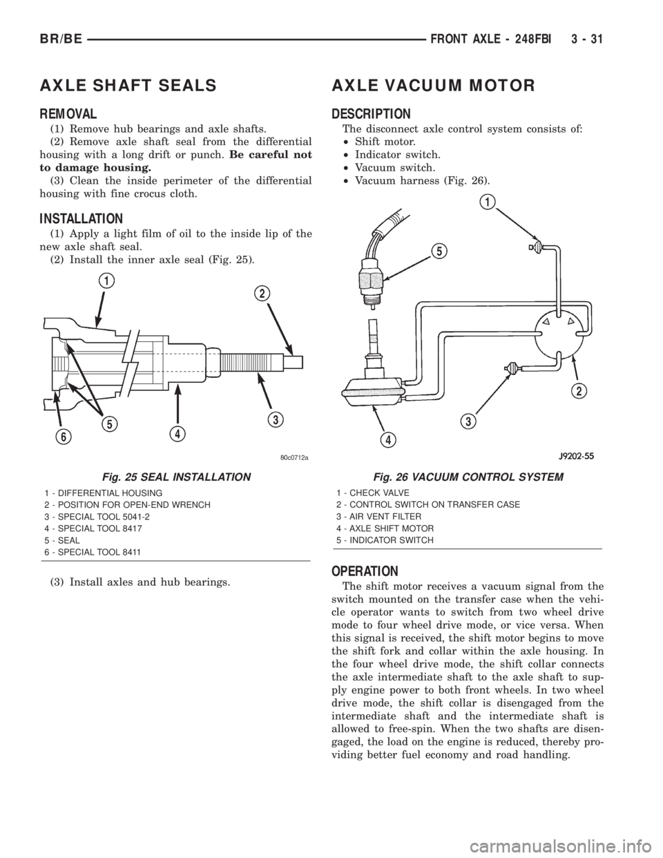
(2) Install the inner axle seal (Fig. 25).
(3) Install axles and hub bearings.
AXLE VACUUM MOTOR
DESCRIPTION
The disconnect axle control system consists of:
²Shift motor.
²Indicator switch.
²Vacuum switch.
²Vacuum harness (Fig. 26).
OPERATION
The shift motor receives a vacuum signal from the
switch mounted on the transfer case when the vehi-
cle operator wants to switch from two wheel drive
mode to four wheel drive mode, or vice versa. When
this signal is received, the shift motor begins to move
the shift fork and collar within the axle housing. In
the four wheel drive mode, the shift collar connects
the axle intermediate shaft to the axle shaft to sup-
ply engine power to both front wheels. In two wheel
drive mode, the shift collar is disengaged from the
intermediate shaft and the intermediate shaft is
allowed to free-spin. When the two shafts are disen-
gaged, the load on the engine is reduced, thereby pro-
viding better fuel economy and road handling.
Fig. 25 SEAL INSTALLATION
1 - DIFFERENTIAL HOUSING
2 - POSITION FOR OPEN-END WRENCH
3 - SPECIAL TOOL 5041-2
4 - SPECIAL TOOL 8417
5 - SEAL
6 - SPECIAL TOOL 8411
Fig. 26 VACUUM CONTROL SYSTEM
1 - CHECK VALVE
2 - CONTROL SWITCH ON TRANSFER CASE
3 - AIR VENT FILTER
4 - AXLE SHIFT MOTOR
5 - INDICATOR SWITCH
BR/BEFRONT AXLE - 248FBI 3 - 31
Page 131 of 2255
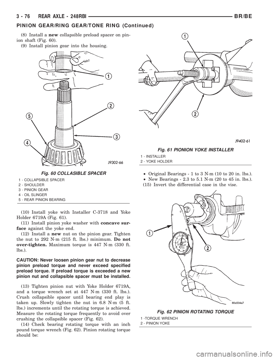
(8) Install anewcollapsible preload spacer on pin-
ion shaft (Fig. 60).
(9) Install pinion gear into the housing.
(10) Install yoke with Installer C-3718 and Yoke
Holder 6719A (Fig. 61).
(11) Install pinion yoke washer withconcave sur-
faceagainst the yoke end.
(12) Install anewnut on the pinion gear. Tighten
the nut to 292 N´m (215 ft. lbs.) minimum.Do not
over-tighten.Maximum torque is 447 N´m (330 ft.
lbs.).
CAUTION: Never loosen pinion gear nut to decrease
pinion preload torque and never exceed specified
preload torque. If preload torque is exceeded a new
pinion nut and collapsible spacer must be installed.
(13) Tighten pinion nut with Yoke Holder 6719A,
and a torque wrench set at 447 N´m (330 ft. lbs.).
Crush collapsible spacer until bearing end play is
taken up. Slowly tighten the nut in 6.8 N´m (5 ft.
lbs.) increments until the rotating torque is achieved.
Measure the rotating torque frequently to avoid over
crushing the collapsible spacer (Fig. 62).
(14) Check bearing rotating torque with an inch
pound torque wrench (Fig. 62). Pinion rotating torque
should be:²Original Bearings-1to3N´m(10to20in.lbs.).
²New Bearings - 2.3 to 5.1 N´m (20 to 45 in. lbs.).
(15) Invert the differential case in the vise.
Fig. 60 COLLASIBLE SPACER
1 - COLLAPSIBLE SPACER
2 - SHOULDER
3 - PINION GEAR
4 - OIL SLINGER
5 - REAR PINION BEARING
Fig. 61 PIONION YOKE INSTALLER
1 - INSTALLER
2 - YOKE HOLDER
Fig. 62 PINION ROTATING TORQUE
1 -TORQUE WRENCH
2 - PINION YOKE
3 - 76 REAR AXLE - 248RBIBR/BE
PINION GEAR/RING GEAR/TONE RING (Continued)
Page 160 of 2255
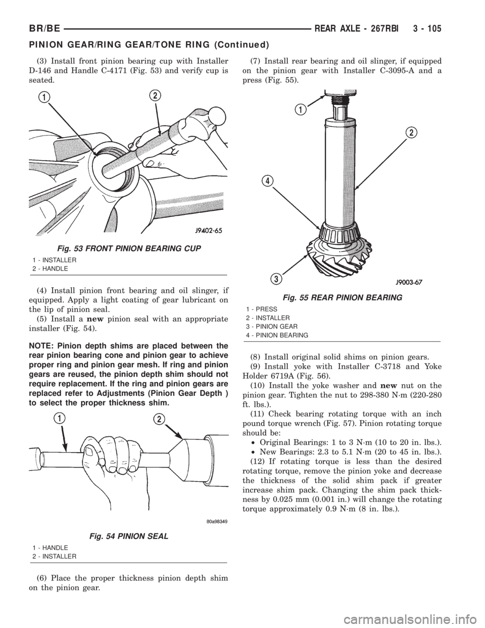
(3) Install front pinion bearing cup with Installer
D-146 and Handle C-4171 (Fig. 53) and verify cup is
seated.
(4) Install pinion front bearing and oil slinger, if
equipped. Apply a light coating of gear lubricant on
the lip of pinion seal.
(5) Install anewpinion seal with an appropriate
installer (Fig. 54).
NOTE: Pinion depth shims are placed between the
rear pinion bearing cone and pinion gear to achieve
proper ring and pinion gear mesh. If ring and pinion
gears are reused, the pinion depth shim should not
require replacement. If the ring and pinion gears are
replaced refer to Adjustments (Pinion Gear Depth )
to select the proper thickness shim.
(6) Place the proper thickness pinion depth shim
on the pinion gear.(7) Install rear bearing and oil slinger, if equipped
on the pinion gear with Installer C-3095-A and a
press (Fig. 55).
(8) Install original solid shims on pinion gears.
(9) Install yoke with Installer C-3718 and Yoke
Holder 6719A (Fig. 56).
(10) Install the yoke washer andnewnut on the
pinion gear. Tighten the nut to 298-380 N´m (220-280
ft. lbs.).
(11) Check bearing rotating torque with an inch
pound torque wrench (Fig. 57). Pinion rotating torque
should be:
²Original Bearings: 1 to 3 N´m (10 to 20 in. lbs.).
²New Bearings: 2.3 to 5.1 N´m (20 to 45 in. lbs.).
(12) If rotating torque is less than the desired
rotating torque, remove the pinion yoke and decrease
the thickness of the solid shim pack if greater
increase shim pack. Changing the shim pack thick-
ness by 0.025 mm (0.001 in.) will change the rotating
torque approximately 0.9 N´m (8 in. lbs.).
Fig. 53 FRONT PINION BEARING CUP
1 - INSTALLER
2 - HANDLE
Fig. 54 PINION SEAL
1 - HANDLE
2 - INSTALLER
Fig. 55 REAR PINION BEARING
1 - PRESS
2 - INSTALLER
3 - PINION GEAR
4 - PINION BEARING
BR/BEREAR AXLE - 267RBI 3 - 105
PINION GEAR/RING GEAR/TONE RING (Continued)