2002 DODGE RAM air bleeding
[x] Cancel search: air bleedingPage 196 of 2255

mile or two. However, if the lining is both soaked and
dirt contaminated, cleaning and/or replacement will
be necessary.
BRAKE LINING CONTAMINATION
Brake lining contamination is mostly a product of
leaking calipers or wheel cylinders, worn seals, driv-
ing through deep water puddles, or lining that has
become covered with grease and grit during repair.
Contaminated lining should be replaced to avoid fur-
ther brake problems.
WHEEL AND TIRE PROBLEMS
Some conditions attributed to brake components
may actually be caused by a wheel or tire problem.
A damaged wheel can cause shudder, vibration and
pull. A worn or damaged tire can also cause pull.
Severely worn tires with very little tread left can
produce a grab-like condition as the tire loses and
recovers traction. Flat-spotted tires can cause vibra-
tion and generate shudder during brake operation. A
tire with internal damage such as a severe bruise,
cut, or ply separation can cause pull and vibration.
BRAKE NOISES
Some brake noise is common with rear drum
brakes and on some disc brakes during the first few
stops after a vehicle has been parked overnight or
stored. This is primarily due to the formation of trace
corrosion (light rust) on metal surfaces. This light
corrosion is typically cleared from the metal surfaces
after a few brake applications causing the noise to
subside.
BRAKE SQUEAK/SQUEAL
Brake squeak or squeal may be due to linings that
are wet or contaminated with brake fluid, grease, or
oil. Glazed linings and rotors with hard spots can
also contribute to squeak. Dirt and foreign material
embedded in the brake lining will also cause squeak/
squeal.
A very loud squeak or squeal is frequently a sign of
severely worn brake lining. If the lining has worn
through to the brake shoes in spots, metal-to-metal
contact occurs. If the condition is allowed to continue,
rotors and drums can become so scored that replace-
ment is necessary.
BRAKE CHATTER
Brake chatter is usually caused by loose or worn
components, or glazed/burnt lining. Rotors with hard
spots can also contribute to chatter. Additional causes
of chatter are out-of-tolerance rotors, brake lining not
securely attached to the shoes, loose wheel bearings
and contaminated brake lining.THUMP/CLUNK NOISE
Thumping or clunk noises during braking are fre-
quentlynotcaused by brake components. In many
cases, such noises are caused by loose or damaged
steering, suspension, or engine components. However,
calipers that bind on the slide surfaces can generate
a thump or clunk noise. In addition, worn out,
improperly adjusted, or improperly assembled rear
brake shoes can also produce a thump noise.
STANDARD PROCEDURE
STANDARD PROCEDURE - MANUAL BLEEDING
Use Mopar brake fluid, or an equivalent quality
fluid meeting SAE J1703-F and DOT 3 standards
only. Use fresh, clean fluid from a sealed container at
all times.
(1) Remove reservoir filler caps and fill reservoir.
(2) If calipers, or wheel cylinders were overhauled,
open all caliper and wheel cylinder bleed screws.
Then close each bleed screw as fluid starts to drip
from it. Top off master cylinder reservoir once more
before proceeding.
(3) Attach one end of bleed hose to bleed screw
and insert opposite end in glass container partially
filled with brake fluid (Fig. 1). Be sure end of bleed
hose is immersed in fluid.
(4)
Open up bleeder, then have a helper press down
the brake pedal. Once the pedal is down close the
bleeder. Repeat bleeding until fluid stream is clear and
free of bubbles. Then move to the next wheel.
Fig. 1 Bleed Hose Setup
1 - BLEED HOSE
2 - FLUID CONTAINER PARTIALLY FILLED WITH FLUID
BR/BEBRAKES - BASE 5 - 7
HYDRAULIC/MECHANICAL (Continued)
Page 197 of 2255
STANDARD PROCEDURE - PRESSURE
BLEEDING
Use Mopar brake fluid, or an equivalent quality
fluid meeting SAE J1703-F and DOT 3 standards
only. Use fresh, clean fluid from a sealed container at
all times.
If pressure bleeding equipment will be used, the
front brake metering valve will have to be held open
to bleed the front brakes. The valve stem is located
in the forward end or top of the combination valve.
The stem must either be pressed inward, or held out-
ward slightly. A spring clip tool or helper is needed to
hold the valve stem in position.
Follow the manufacturers instructions carefully
when using pressure equipment. Do not exceed the
tank manufacturers pressure recommendations. Gen-
erally, a tank pressure of 15-20 psi is sufficient for
bleeding.
Fill the bleeder tank with recommended fluid and
purge air from the tank lines before bleeding.
Do not pressure bleed without a proper master cyl-
inder adapter. The wrong adapter can lead to leak-
age, or drawing air back into the system. Use
adapter provided with the equipment or Adapter
6921.
BRAKE LINES
STANDARD PROCEDURE
STANDARD PROCEDURE - DOUBLE INVERTED
FLARING
A preformed metal brake tube is recommended and
preferred for all repairs. However, double-wall steel
tube can be used for emergency repair when factory
replacement parts are not readily available.
(1) Cut off damaged tube with Tubing Cutter.
(2) Ream cut edges of tubing to ensure proper
flare.
(3) Install replacement tube nut on the tube.
(4) Insert tube in flaring tool.
(5) Place gauge form over the end of the tube.
(6) Push tubing through flaring tool jaws until
tube contacts recessed notch in gauge that matches
tube diameter.
(7) Tighten the tool bar on the tube
(8) Insert plug on gauge in the tube. Then swing
compression disc over gauge and center tapered flar-
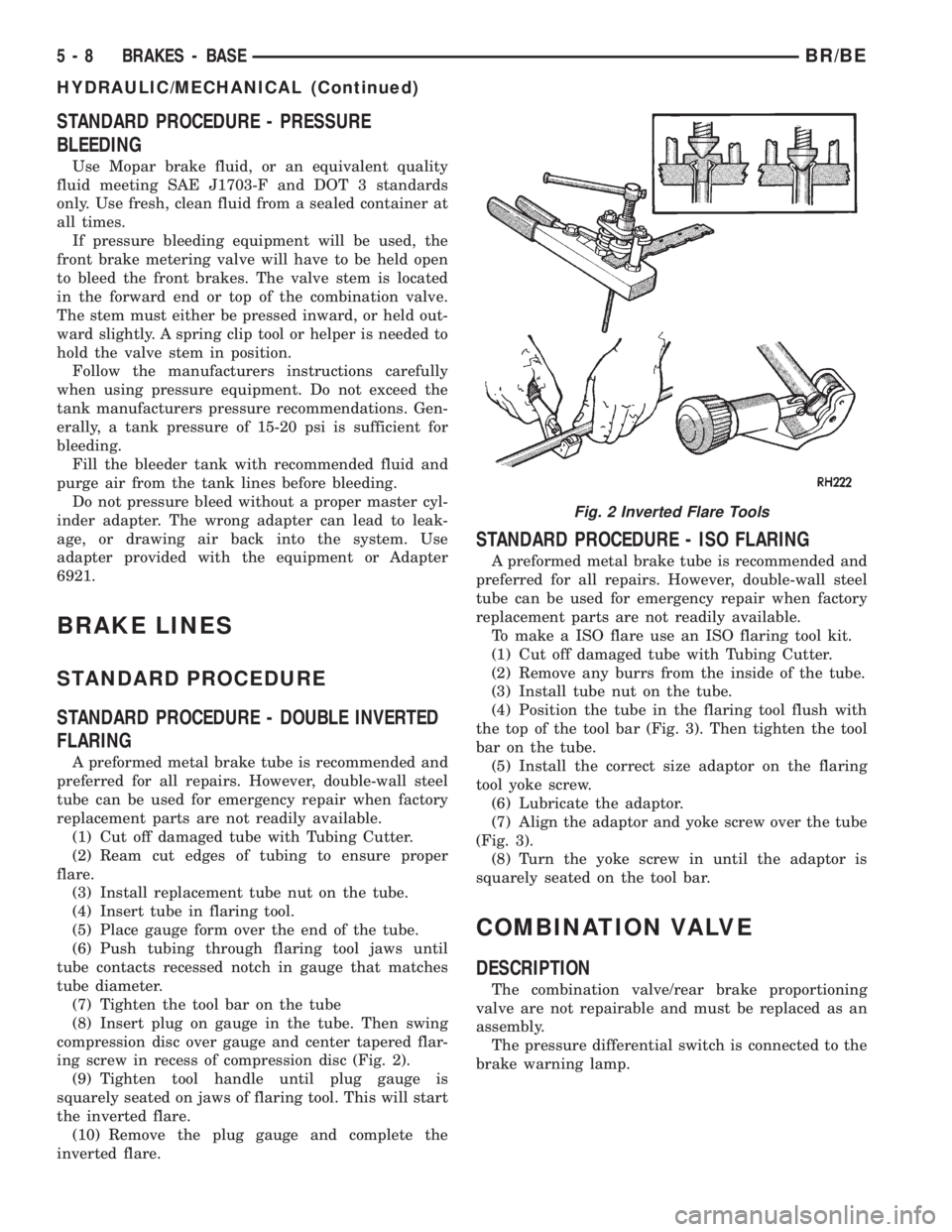
ing screw in recess of compression disc (Fig. 2).
(9) Tighten tool handle until plug gauge is
squarely seated on jaws of flaring tool. This will start
the inverted flare.
(10) Remove the plug gauge and complete the
inverted flare.
STANDARD PROCEDURE - ISO FLARING
A preformed metal brake tube is recommended and
preferred for all repairs. However, double-wall steel
tube can be used for emergency repair when factory
replacement parts are not readily available.
To make a ISO flare use an ISO flaring tool kit.
(1) Cut off damaged tube with Tubing Cutter.
(2) Remove any burrs from the inside of the tube.
(3) Install tube nut on the tube.
(4) Position the tube in the flaring tool flush with
the top of the tool bar (Fig. 3). Then tighten the tool
bar on the tube.
(5) Install the correct size adaptor on the flaring
tool yoke screw.
(6) Lubricate the adaptor.
(7) Align the adaptor and yoke screw over the tube
(Fig. 3).
(8) Turn the yoke screw in until the adaptor is
squarely seated on the tool bar.
COMBINATION VALVE
DESCRIPTION
The combination valve/rear brake proportioning
valve are not repairable and must be replaced as an
assembly.
The pressure differential switch is connected to the
brake warning lamp.
Fig. 2 Inverted Flare Tools
5 - 8 BRAKES - BASEBR/BE
HYDRAULIC/MECHANICAL (Continued)
Page 208 of 2255
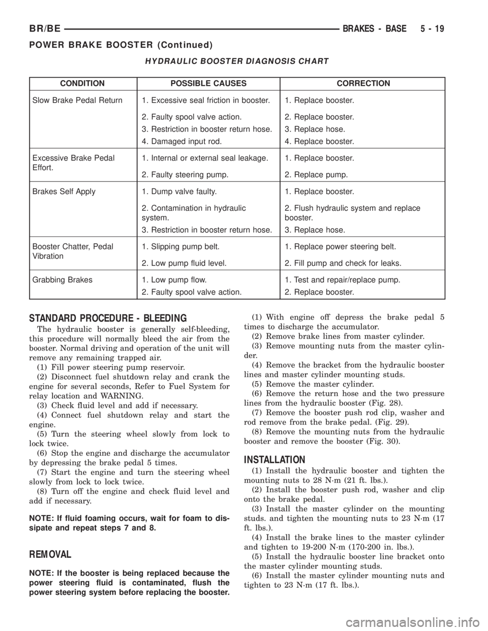
HYDRAULIC BOOSTER DIAGNOSIS CHART
CONDITION POSSIBLE CAUSES CORRECTION
Slow Brake Pedal Return 1. Excessive seal friction in booster. 1. Replace booster.
2. Faulty spool valve action. 2. Replace booster.
3. Restriction in booster return hose. 3. Replace hose.
4. Damaged input rod. 4. Replace booster.
Excessive Brake Pedal
Effort.1. Internal or external seal leakage. 1. Replace booster.
2. Faulty steering pump. 2. Replace pump.
Brakes Self Apply 1. Dump valve faulty. 1. Replace booster.
2. Contamination in hydraulic
system.2. Flush hydraulic system and replace
booster.
3. Restriction in booster return hose. 3. Replace hose.
Booster Chatter, Pedal
Vibration1. Slipping pump belt. 1. Replace power steering belt.
2. Low pump fluid level. 2. Fill pump and check for leaks.
Grabbing Brakes 1. Low pump flow. 1. Test and repair/replace pump.
2. Faulty spool valve action. 2. Replace booster.
STANDARD PROCEDURE - BLEEDING
The hydraulic booster is generally self-bleeding,
this procedure will normally bleed the air from the
booster. Normal driving and operation of the unit will
remove any remaining trapped air.
(1) Fill power steering pump reservoir.
(2) Disconnect fuel shutdown relay and crank the
engine for several seconds, Refer to Fuel System for
relay location and WARNING.
(3) Check fluid level and add if necessary.
(4) Connect fuel shutdown relay and start the
engine.
(5) Turn the steering wheel slowly from lock to
lock twice.
(6) Stop the engine and discharge the accumulator
by depressing the brake pedal 5 times.
(7) Start the engine and turn the steering wheel
slowly from lock to lock twice.
(8) Turn off the engine and check fluid level and
add if necessary.
NOTE: If fluid foaming occurs, wait for foam to dis-
sipate and repeat steps 7 and 8.
REMOVAL
NOTE: If the booster is being replaced because the
power steering fluid is contaminated, flush the
power steering system before replacing the booster.(1) With engine off depress the brake pedal 5
times to discharge the accumulator.
(2) Remove brake lines from master cylinder.
(3) Remove mounting nuts from the master cylin-
der.
(4) Remove the bracket from the hydraulic booster
lines and master cylinder mounting studs.
(5) Remove the master cylinder.
(6) Remove the return hose and the two pressure
lines from the hydraulic booster (Fig. 28).
(7) Remove the booster push rod clip, washer and
rod remove from the brake pedal. (Fig. 29).
(8) Remove the mounting nuts from the hydraulic
booster and remove the booster (Fig. 30).
INSTALLATION
(1) Install the hydraulic booster and tighten the
mounting nuts to 28 N´m (21 ft. lbs.).
(2) Install the booster push rod, washer and clip
onto the brake pedal.
(3) Install the master cylinder on the mounting
studs. and tighten the mounting nuts to 23 N´m (17
ft. lbs.).
(4) Install the brake lines to the master cylinder
and tighten to 19-200 N´m (170-200 in. lbs.).
(5) Install the hydraulic booster line bracket onto
the master cylinder mounting studs.
(6) Install the master cylinder mounting nuts and
tighten to 23 N´m (17 ft. lbs.).
BR/BEBRAKES - BASE 5 - 19
POWER BRAKE BOOSTER (Continued)
Page 216 of 2255
(4) Clamp hose shut between vacuum source and
check valve.
(5) Stop engine and observe vacuum gauge.
(6) If vacuum drops more than one inch HG (33
millibars) within 15 seconds, booster diaphragm or
check valve is faulty.
POWER BOOSTER CHECK VALVE TEST
(1) Disconnect vacuum hose from check valve.
(2) Remove check valve and valve seal from
booster.
(3) Use a hand operated vacuum pump for test.
(4) Apply 15-20 inches vacuum at large end of
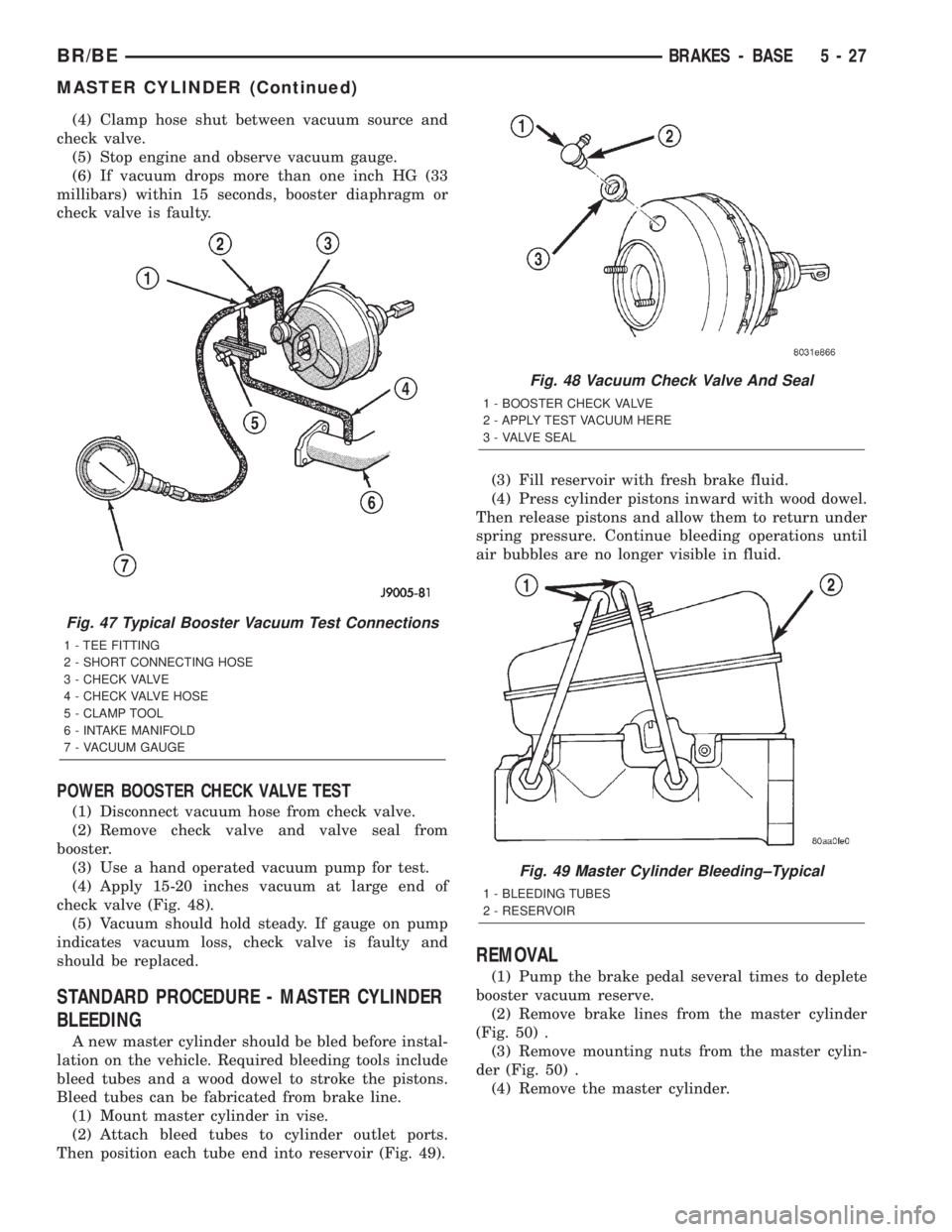
check valve (Fig. 48).
(5) Vacuum should hold steady. If gauge on pump
indicates vacuum loss, check valve is faulty and
should be replaced.
STANDARD PROCEDURE - MASTER CYLINDER
BLEEDING
A new master cylinder should be bled before instal-
lation on the vehicle. Required bleeding tools include
bleed tubes and a wood dowel to stroke the pistons.
Bleed tubes can be fabricated from brake line.
(1) Mount master cylinder in vise.
(2) Attach bleed tubes to cylinder outlet ports.
Then position each tube end into reservoir (Fig. 49).(3) Fill reservoir with fresh brake fluid.
(4) Press cylinder pistons inward with wood dowel.
Then release pistons and allow them to return under
spring pressure. Continue bleeding operations until
air bubbles are no longer visible in fluid.
REMOVAL
(1) Pump the brake pedal several times to deplete
booster vacuum reserve.
(2) Remove brake lines from the master cylinder
(Fig. 50) .
(3) Remove mounting nuts from the master cylin-
der (Fig. 50) .
(4) Remove the master cylinder.
Fig. 47 Typical Booster Vacuum Test Connections
1 - TEE FITTING
2 - SHORT CONNECTING HOSE
3 - CHECK VALVE
4 - CHECK VALVE HOSE
5 - CLAMP TOOL
6 - INTAKE MANIFOLD
7 - VACUUM GAUGE
Fig. 48 Vacuum Check Valve And Seal
1 - BOOSTER CHECK VALVE
2 - APPLY TEST VACUUM HERE
3 - VALVE SEAL
Fig. 49 Master Cylinder Bleeding±Typical
1 - BLEEDING TUBES
2 - RESERVOIR
BR/BEBRAKES - BASE 5 - 27
MASTER CYLINDER (Continued)
Page 225 of 2255
OPERATION
Battery voltage is supplied to the CAB when a
speed of 15 miles per hour is reached. The CAB per-
forms a system initialization procedure at this point.
Initialization consists of a static and dynamic self
check of system electrical components.
The static and dynamic checks occurs at ignition
start up. During the dynamic check, the CAB briefly
cycles the pump and solenoids to verify operation. An
audible noise may be heard during this self check.
This noise should be considered normal.
If an ABS component exhibits a fault during ini-
tialization, the CAB illuminates the amber warning
light and registers a fault code in the microprocessor
memory.
The CAB monitors wheel speed sensor inputs con-
tinuously while the vehicle is in motion. However,
the CAB will not activate any ABS components as
long as sensor inputs indicate normal braking.
During normal braking, the master cylinder, power
booster and wheel brake units all function as they
would in a vehicle without ABS. The HCU compo-
nents are not activated.
The purpose of the antilock system is to prevent
wheel lockup during periods of high wheel slip. Pre-
venting lockup helps maintain vehicle braking action
and steering control.
The antilock CAB activates the system whenever
sensor signals indicate periods of wheel slip. Periods
of wheel slip occur when brake stops involve high
pedal pressure and rate of vehicle deceleration.
The antilock system prevents lockup during a
wheel slip condition by modulating fluid apply pres-
sure to the wheel brake units.
Brake fluid apply pressure is modulated according
to wheel speed, degree of slip and rate of decelera-
tion. Sensors at each front wheel convert wheel speed
into electrical signals. These signals are transmitted
to the CAB for processing and determination of
wheel slip and deceleration rate.
The ABS system has three fluid pressure control
channels. The front brakes are controlled separately
and the rear brakes in tandem. A speed sensor input
signal indicating a wheel slip condition activates the
CAB antilock program.
There are Two solenoid valves (Isolation and Dump
valve) which are used in each antilock control chan-
nel. The valves are all located within the HCU valve
body and work in pairs to either increase, hold, or
decrease apply pressure as needed in the individual
control channels.
During an ABS stop the ISO valve actuates, Stop-
ping anymore pressure build Ðup to the calipers.
Then the Dump valve dumps off pressure until the
wheel unlocks. This will continue until the wheels
quit slipping altogether.
DIAGNOSIS AND TESTING - ANTILOCK
BRAKES
The ABS brake system performs several self-tests
every time the ignition switch is turned on and the
vehicle is driven. The CAB monitors the systems
input and output circuits to verify the system is oper-
ating correctly. If the on board diagnostic system
senses that a circuit is malfunctioning the system
will set a trouble code in its memory.
NOTE: An audible noise may be heard during the
self-test. This noise should be considered normal.
NOTE: The MDS or DRB III scan tool is used to
diagnose the ABS system. For additional informa-
tion refer to the Antilock Brake section in Group
8W. For test procedures refer to the Chassis Diag-
nostic Manual.
STANDARD PROCEDURE
STANDARD PROCEDURE - RWAL SERVICE
PRECAUTIONS
The RWAL uses an electronic control module, the
CAB. This module is designed to withstand normal
current draws associated with vehicle operation.
Care must be taken to avoid overloading the CAB
circuits.In testing for open or short circuits, do
not ground or apply voltage to any of the cir-
cuits unless instructed to do so for a diagnostic
procedure.These circuits should only be tested
using a high impedance multi-meter or the DRB
tester as described in this section. Power should
never be removed or applied to any control module
with the ignition in the ON position. Before removing
or connecting battery cables, fuses, or connectors,
always turn the ignition to the OFF position.
CAUTION: Use only factory wiring harnesses. Do
not cut or splice wiring to the brake circuits. The
addition of after-market electrical equipment (car
phone, radar detector, citizen band radio, trailer
lighting, trailer brakes, ect.) on a vehicle equipped
with antilock brakes may affect the function of the
antilock brake system.
STANDARD PROCEDURE - BLEEDING ABS
BRAKE SYSTEM
ABS system bleeding requires conventional bleed-
ing methods plus use of the DRB scan tool. The pro-
cedure involves performing a base brake bleeding,
followed by use of the scan tool to cycle and bleed the
5 - 36 BRAKES - ABSBR/BE
BRAKES - ABS (Continued)
Page 226 of 2255
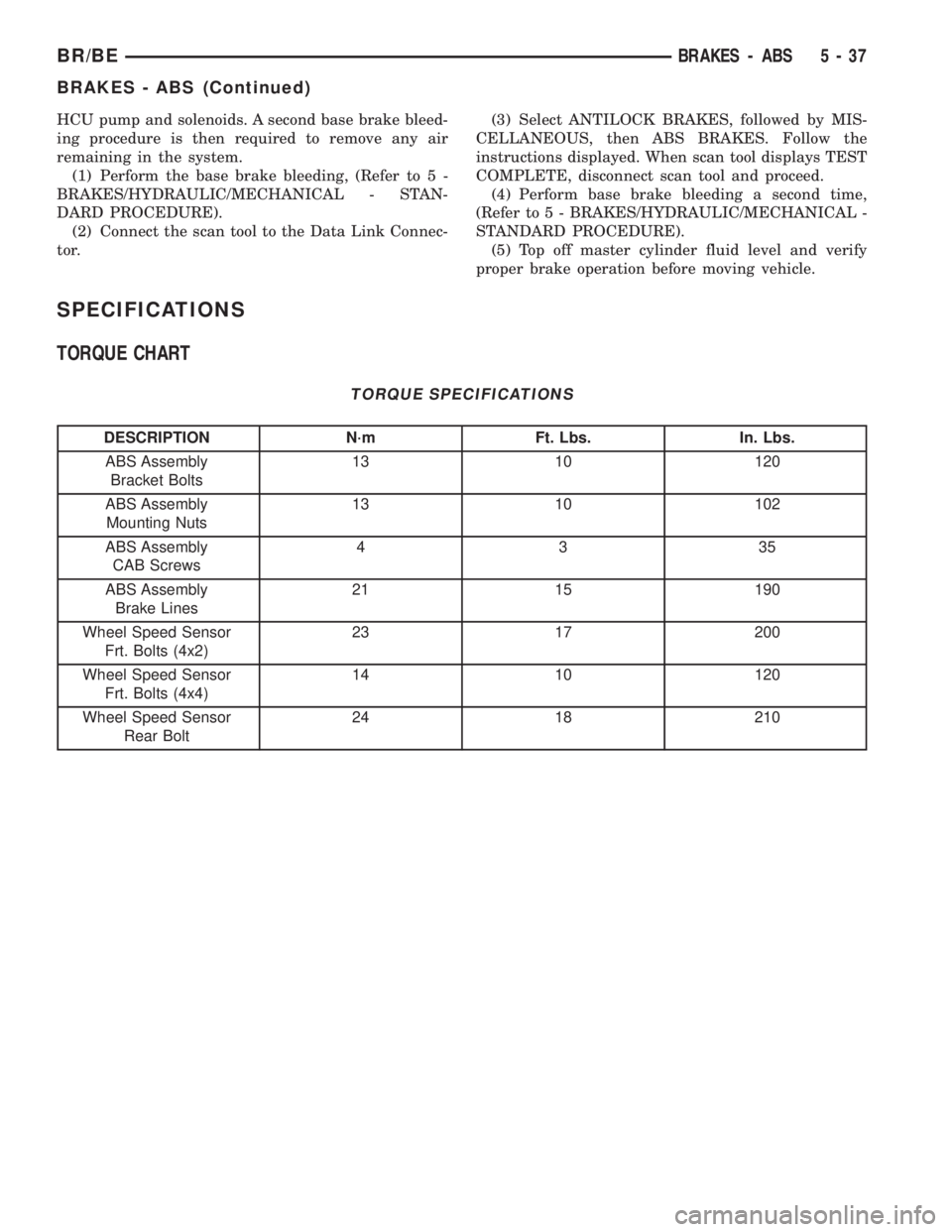
HCU pump and solenoids. A second base brake bleed-
ing procedure is then required to remove any air
remaining in the system.
(1) Perform the base brake bleeding, (Refer to 5 -
BRAKES/HYDRAULIC/MECHANICAL - STAN-
DARD PROCEDURE).
(2) Connect the scan tool to the Data Link Connec-
tor.(3) Select ANTILOCK BRAKES, followed by MIS-
CELLANEOUS, then ABS BRAKES. Follow the
instructions displayed. When scan tool displays TEST
COMPLETE, disconnect scan tool and proceed.
(4) Perform base brake bleeding a second time,
(Refer to 5 - BRAKES/HYDRAULIC/MECHANICAL -
STANDARD PROCEDURE).
(5) Top off master cylinder fluid level and verify
proper brake operation before moving vehicle.
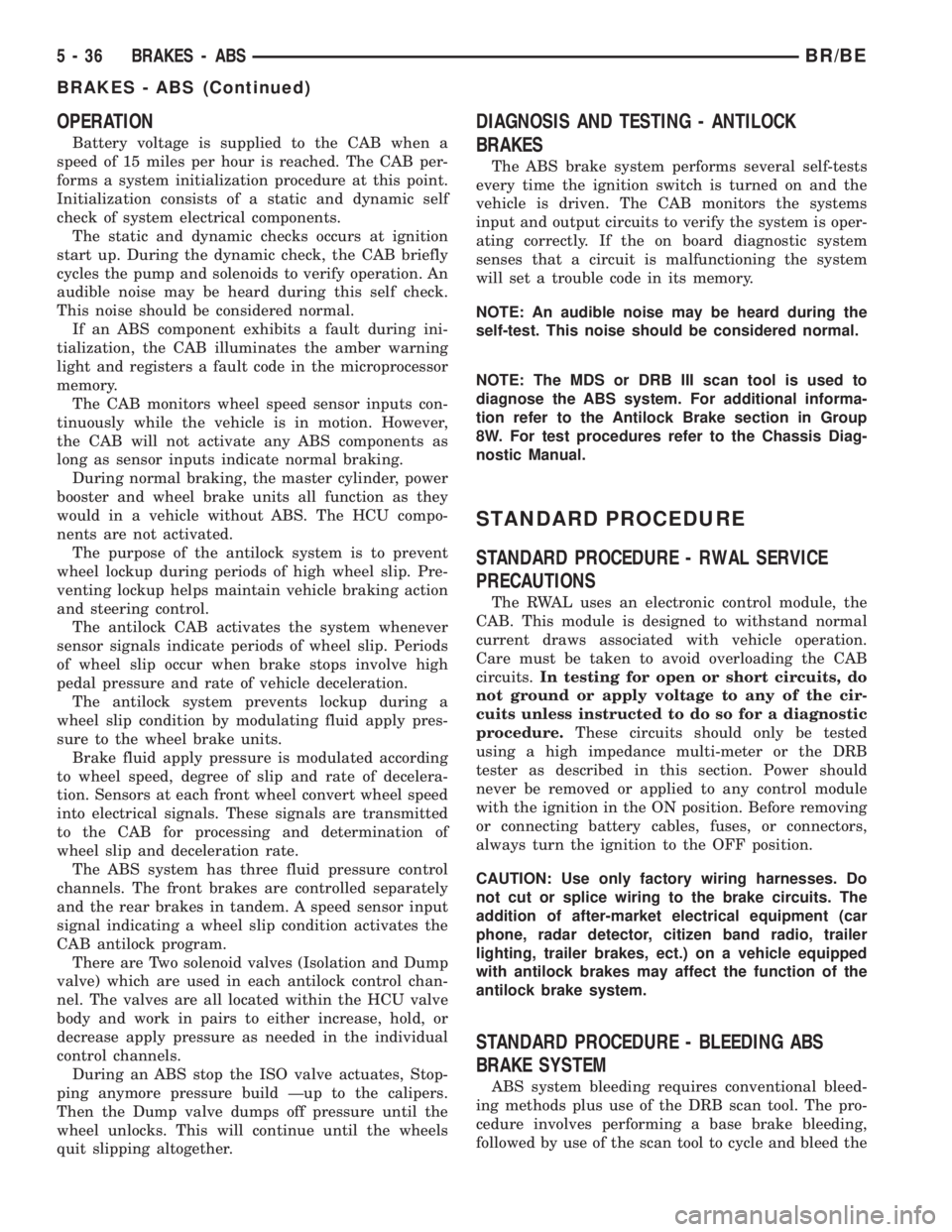
SPECIFICATIONS
TORQUE CHART
TORQUE SPECIFICATIONS
DESCRIPTION N´m Ft. Lbs. In. Lbs.
ABS Assembly
Bracket Bolts13 10 120
ABS Assembly
Mounting Nuts13 10 102
ABS Assembly
CAB Screws4335
ABS Assembly
Brake Lines21 15 190
Wheel Speed Sensor
Frt. Bolts (4x2)23 17 200
Wheel Speed Sensor
Frt. Bolts (4x4)14 10 120
Wheel Speed Sensor
Rear Bolt24 18 210
BR/BEBRAKES - ABS 5 - 37
BRAKES - ABS (Continued)
Page 1301 of 2255
FUEL DELIVERY - GASOLINE
DESCRIPTION - FUEL DELIVERY SYSTEM
The fuel delivery system consists of:
²the fuel pump module containing the electric
fuel pump, fuel filter/fuel pressure regulator, rollover
valve (certain modules), fuel gauge sending unit (fuel
level sensor) and a separate fuel filter located at bot-
tom of pump module
²fuel tubes/lines/hoses
²quick-connect fittings
²fuel injector rail
²fuel injectors
²fuel tank
²fuel tank filler/vent tube assembly
²fuel tank filler tube cap
²accelerator pedal
²throttle cable
OPERATION - FUEL DELIVERY SYSTEM
Fuel is returned through the fuel pump module
and back into the fuel tank through the fuel filter/
fuel pressure regulator. A separate fuel return line
from the engine to the tank is not used with any gas-
oline powered engine.
The fuel tank assembly consists of: the fuel tank,
fuel pump module assembly, fuel pump module lock-
nut/gasket and fuel tank check valve(s) (refer to 25,
Emission Control System for Fuel Tank Check Valve
information).
A fuel filler/vent tube assembly using a pressure/
vacuum, 1/4 turn fuel filler cap is used. The fuel
filler tube contains a flap door located below the fuel
fill cap.
Also to be considered part of the fuel system is the
evaporation control system. This is designed to
reduce the emission of fuel vapors into the atmo-
sphere. The description and function of the Evapora-
tive Control System is found in 25, Emission Control
Systems.
Both fuel filters (at bottom of fuel pump module
and within fuel pressure regulator) are designed for
extended service. They do not require normal sched-
uled maintenance. Filters should only be replaced if
a diagnostic procedure indicates to do so.
DIAGNOSIS AND TESTING - FUEL PRESSURE
LEAK DOWN TEST
Use this test in conjunction with the Fuel Pump
Pressure Test and Fuel Pump Capacity Test.
Check Valve Operation:The electric fuel pump
outlet contains a one-way check valve to prevent fuel
flow back into the tank and to maintain fuel supply
line pressure (engine warm) when pump is not oper-
ational. It is also used to keep the fuel supply linefull of gasoline when pump is not operational. After
the vehicle has cooled down, fuel pressure may drop
to 0 psi (cold fluid contracts), but liquid gasoline will
remain in fuel supply line between the check valve
and fuel injectors.Fuel pressure that has
dropped to 0 psi on a cooled down vehicle
(engine off) is a normal condition.When the elec-
tric fuel pump is activated, fuel pressure should
immediately(1±2 seconds) rise to specification.
Abnormally long periods of cranking to restart a
hotengine that has been shut down for a short
period of time may be caused by:
²Fuel pressure bleeding past a fuel injector(s).
²Fuel pressure bleeding past the check valve in
the fuel pump module.
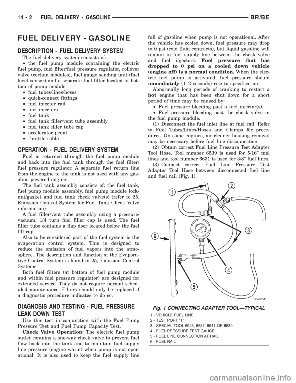
(1) Disconnect the fuel inlet line at fuel rail. Refer
to Fuel Tubes/Lines/Hoses and Clamps for proce-
dures. On some engines, air cleaner housing removal
may be necessary before fuel line disconnection.
(2) Obtain correct Fuel Line Pressure Test Adapter
Tool Hose. Tool number 6539 is used for 5/16º fuel
lines and tool number 6631 is used for 3/8º fuel lines.
(3) Connect correct Fuel Line Pressure Test
Adapter Tool Hose between disconnected fuel line
and fuel rail (Fig. 1).
Fig. 1 CONNECTING ADAPTER TOOLÐTYPICAL
1 - VEHICLE FUEL LINE
2 - TEST PORT ªTº
3 - SPECIAL TOOL 6923, 6631, 6541 OR 6539
4 - FUEL PRESSURE TEST GAUGE
5 - FUEL LINE CONNECTION AT RAIL
6 - FUEL RAIL
14 - 2 FUEL DELIVERY - GASOLINEBR/BE
Page 1359 of 2255
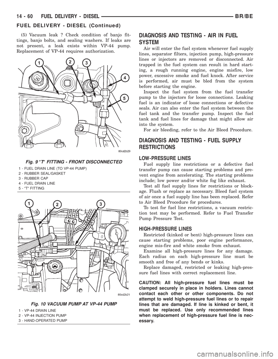
(5) Vacuum leak ? Check condition of banjo fit-
tings, banjo bolts, and sealing washers. If leaks are
not present, a leak exists within VP-44 pump.
Replacement of VP-44 requires authorization.DIAGNOSIS AND TESTING - AIR IN FUEL
SYSTEM
Air will enter the fuel system whenever fuel supply
lines, separator filters, injection pump, high-pressure
lines or injectors are removed or disconnected. Air
trapped in the fuel system can result in hard start-
ing, a rough running engine, engine misfire, low
power, excessive smoke and fuel knock. After service
is performed, air must be bled from the system
before starting the engine.
Inspect the fuel system from the fuel transfer
pump to the injectors for loose connections. Leaking
fuel is an indicator of loose connections or defective
seals. Air can also enter the fuel system between the
fuel tank and the transfer pump. Inspect the fuel
tank and fuel lines for damage that might allow air
into the system.
For air bleeding, refer to the Air Bleed Procedure.
DIAGNOSIS AND TESTING - FUEL SUPPLY
RESTRICTIONS
LOW-PRESSURE LINES
Fuel supply line restrictions or a defective fuel
transfer pump can cause starting problems and pre-
vent engine from accelerating. The starting problems
include; low power and/or white fog like exhaust.
Test all fuel supply lines for restrictions or block-
age. Flush or replace as necessary. Bleed fuel system
of air once a fuel supply line has been replaced. Refer
to Air Bleed Procedure for procedures.
To test for fuel line restrictions, a vacuum restric-
tion test may be performed. Refer to Fuel Transfer
Pump Pressure Test.
HIGH-PRESSURE LINES
Restricted (kinked or bent) high-pressure lines can
cause starting problems, poor engine performance,
engine mis-fire and white smoke from exhaust.
Examine all high-pressure lines for any damage.
Each radius on each high-pressure line must be
smooth and free of any bends or kinks.
Replace damaged, restricted or leaking high-pres-
sure fuel lines with correct replacement line.
CAUTION: All high-pressure fuel lines must be
clamped securely in place in holders. Lines cannot
contact each other or other components. Do not
attempt to weld high-pressure fuel lines or to repair
lines that are damaged. If line is kinked or bent, it
must be replaced. Use only recommended lines
when replacement of high-pressure fuel line is nec-
essary.
Fig. 9(T(FITTING - FRONT DISCONNECTED
1 - FUEL DRAIN LINE (TO VP-44 PUMP)
2 - RUBBER SEAL/GASKET
3 - RUBBER CAP
4 - FUEL DRAIN LINE
5-9T9FITTING
Fig. 10 VACUUM PUMP AT VP-44 PUMP
1 - VP-44 DRAIN LINE
2 - VP-44 INJECTION PUMP
3 - HAND-OPERATED PUMP
14 - 60 FUEL DELIVERY - DIESELBR/BE
FUEL DELIVERY - DIESEL (Continued)