2002 DODGE RAM air bleeding
[x] Cancel search: air bleedingPage 1360 of 2255
STANDARD PROCEDURE
STANDARD PROCEDURES - WATER DRAINING
AT FUEL FILTER
Refer to Fuel Filter/Water Separator removal/in-
stallation for procedures.
STANDARD PROCEDURES - CLEANING FUEL
SYSTEM PARTS
CAUTION: Cleanliness cannot be overemphasized
when handling or replacing diesel fuel system com-
ponents. This especially includes the fuel injectors,
high-pressure fuel lines and fuel injection pump.
Very tight tolerances are used with these parts. Dirt
contamination could cause rapid part wear and pos-
sible plugging of fuel injector nozzle tip holes. This
in turn could lead to possible engine misfire.
Always wash/clean any fuel system component
thoroughly before disassembly and then air dry.
Cap or cover any open part after disassembly.
Before assembly, examine each part for dirt, grease
or other contaminants and clean if necessary. When
installing new parts, lubricate them with clean
engine oil or clean diesel fuel only.
STANDARD PROCEDURE - AIR BLEED
A certain amount of air becomes trapped in the
fuel system when fuel system components on the
supply and/or high-pressure side are serviced or
replaced. Primary air bleeding is accomplished using
the electric fuel transfer (lift) pump. If the vehicle
has been allowed to run completely out of fuel, the
fuel injectors must also be bled as the fuel injection
pumpis notself-bleeding (priming).
Servicing or replacing components on the fuel
return side will not require air bleeding.
WARNING: DO NOT BLEED AIR FROM THE FUEL
SYSTEM OF A HOT ENGINE.
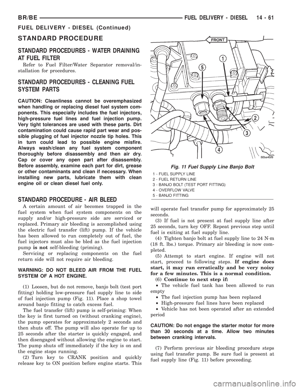
(1) Loosen, but do not remove, banjo bolt (test port
fitting) holding low-pressure fuel supply line to side
of fuel injection pump (Fig. 11). Place a shop towel
around banjo fitting to catch excess fuel.
The fuel transfer (lift) pump is self-priming: When
the key is first turned on (without cranking engine),
the pump operates for approximately 2 seconds and
then shuts off. The pump will also operate for up to
25 seconds after the starter is quickly engaged, and
then disengaged without allowing the engine to start.
The pump shuts off immediately if the key is on and
the engine stops running.
(2) Turn key to CRANK position and quickly
release key to ON position before engine starts. Thiswill operate fuel transfer pump for approximately 25
seconds.
(3) If fuel is not present at fuel supply line after
25 seconds, turn key OFF. Repeat previous step until
fuel is exiting at fuel supply line.
(4) Tighten banjo bolt at fuel supply line to 24 N´m
(18 ft. lbs.) torque. Primary air bleeding is now com-
pleted.
(5) Attempt to start engine. If engine will not
start, proceed to following steps.If engine does
start, it may run erratically and be very noisy
for a few minutes. This is a normal condition.
(6)Continue to next step if:
²The vehicle fuel tank has been allowed to run
empty
²The fuel injection pump has been replaced
²High-pressure fuel lines have been replaced
²Vehicle has not been operated after an extended
period
CAUTION: Do not engage the starter motor for more
than 30 seconds at a time. Allow two minutes
between cranking intervals.
(7) Perform previous air bleeding procedure steps
using fuel transfer pump. Be sure fuel is present at
fuel supply line (Fig. 11) before proceeding.
Fig. 11 Fuel Supply Line Banjo Bolt
1 - FUEL SUPPLY LINE
2 - FUEL RETURN LINE
3 - BANJO BOLT (TEST PORT FITTING)
4 - OVERFLOW VALVE
5 - BANJO FITTING
BR/BEFUEL DELIVERY - DIESEL 14 - 61
FUEL DELIVERY - DIESEL (Continued)
Page 1361 of 2255
(8) Crank the engine for 30 seconds at a time to
allow air trapped in the injection pump to vent out
the drain manifold.
WARNING: THE FUEL INJECTION PUMP SUPPLIES
EXTREMELY HIGH FUEL PRESSURE TO EACH INDI-
VIDUAL INJECTOR THROUGH THE HIGH-PRES-
SURE LINES. FUEL UNDER THIS AMOUNT OF
PRESSURE CAN PENETRATE THE SKIN AND
CAUSE PERSONAL INJURY. WEAR SAFETY GOG-
GLES AND ADEQUATE PROTECTIVE CLOTHING
AND AVOID CONTACT WITH FUEL SPRAY WHEN
BLEEDING HIGH-PRESSURE FUEL LINES.
WARNING: ENGINE MAY START WHILE CRANKING
STARTER MOTOR.
Engine may start, may run erratically and be
very noisy for a few minutes. This is a normal
condition.
(9) Thoroughly clean area around injector fittings
where they join injector connector tubes.
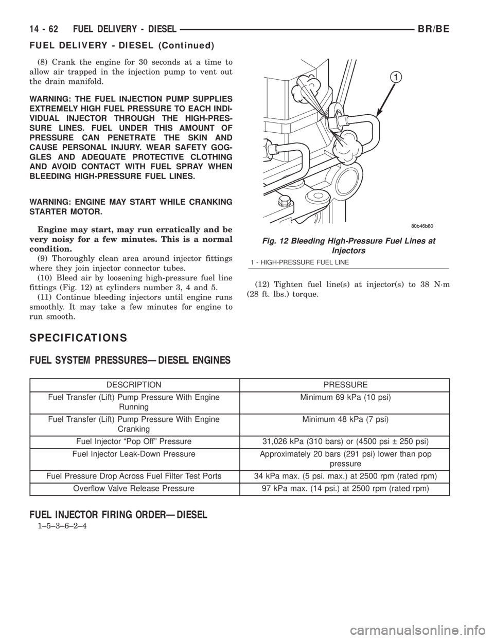
(10) Bleed air by loosening high-pressure fuel line
fittings (Fig. 12) at cylinders number 3, 4 and 5.
(11) Continue bleeding injectors until engine runs
smoothly. It may take a few minutes for engine to
run smooth.(12) Tighten fuel line(s) at injector(s) to 38 N´m
(28 ft. lbs.) torque.
SPECIFICATIONS
FUEL SYSTEM PRESSURESÐDIESEL ENGINES
DESCRIPTION PRESSURE
Fuel Transfer (Lift) Pump Pressure With Engine
RunningMinimum 69 kPa (10 psi)
Fuel Transfer (Lift) Pump Pressure With Engine
CrankingMinimum 48 kPa (7 psi)
Fuel Injector ªPop Offº Pressure 31,026 kPa (310 bars) or (4500 psi 250 psi)
Fuel Injector Leak-Down Pressure Approximately 20 bars (291 psi) lower than pop
pressure
Fuel Pressure Drop Across Fuel Filter Test Ports 34 kPa max. (5 psi. max.) at 2500 rpm (rated rpm)
Overflow Valve Release Pressure 97 kPa max. (14 psi.) at 2500 rpm (rated rpm)
FUEL INJECTOR FIRING ORDERÐDIESEL
1±5±3±6±2±4
Fig. 12 Bleeding High-Pressure Fuel Lines at
Injectors
1 - HIGH-PRESSURE FUEL LINE
14 - 62 FUEL DELIVERY - DIESELBR/BE
FUEL DELIVERY - DIESEL (Continued)
Page 1364 of 2255
(c) Check condition of o-ring.
(d) Inspect the 2 WIF sensor probes. Carefully
clean contaminants from sensor probes with a cloth
if necessary. Replace sensor if probes are covered
with contaminants and will not clean up.
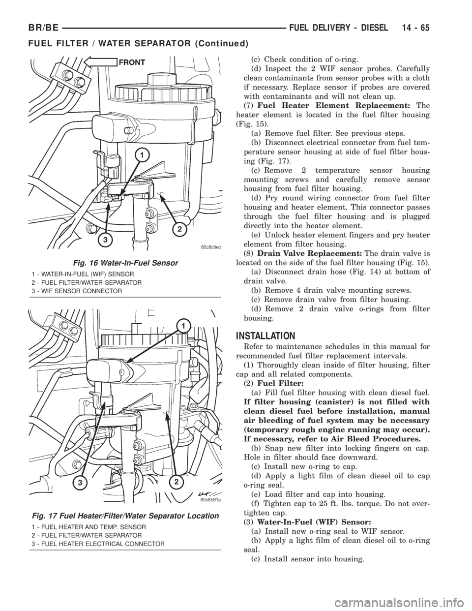
(7)Fuel Heater Element Replacement:The
heater element is located in the fuel filter housing
(Fig. 15).
(a) Remove fuel filter. See previous steps.
(b) Disconnect electrical connector from fuel tem-
perature sensor housing at side of fuel filter hous-
ing (Fig. 17).
(c) Remove 2 temperature sensor housing
mounting screws and carefully remove sensor
housing from fuel filter housing.
(d) Pry round wiring connector from fuel filter
housing and heater element. This connector passes
through the fuel filter housing and is plugged
directly into the heater element.
(e) Unlock heater element fingers and pry heater
element from filter housing.
(8)Drain Valve Replacement:The drain valve is
located on the side of the fuel filter housing (Fig. 15).
(a) Disconnect drain hose (Fig. 14) at bottom of
drain valve.
(b) Remove 4 drain valve mounting screws.
(c) Remove drain valve from filter housing.
(d) Remove 2 drain valve o-rings from filter
housing.
INSTALLATION
Refer to maintenance schedules in this manual for
recommended fuel filter replacement intervals.
(1) Thoroughly clean inside of filter housing, filter
cap and all related components.
(2)Fuel Filter:
(a) Fill fuel filter housing with clean diesel fuel.
If filter housing (canister) is not filled with
clean diesel fuel before installation, manual
air bleeding of fuel system may be necessary
(temporary rough engine running may occur).
If necessary, refer to Air Bleed Procedures.
(b) Snap new filter into locking fingers on cap.
Hole in filter should face downward.
(c) Install new o-ring to cap.
(d) Apply a light film of clean diesel oil to cap
o-ring seal.
(e) Load filter and cap into housing.
(f) Tighten cap to 25 ft. lbs. torque. Do not over-
tighten cap.
(3)Water-In-Fuel (WIF) Sensor:
(a) Install new o-ring seal to WIF sensor.
(b) Apply a light film of clean diesel oil to o-ring
seal.
(c) Install sensor into housing.
Fig. 16 Water-In-Fuel Sensor
1 - WATER-IN-FUEL (WIF) SENSOR
2 - FUEL FILTER/WATER SEPARATOR
3 - WIF SENSOR CONNECTOR
Fig. 17 Fuel Heater/Filter/Water Separator Location
1 - FUEL HEATER AND TEMP. SENSOR
2 - FUEL FILTER/WATER SEPARATOR
3 - FUEL HEATER ELECTRICAL CONNECTOR
BR/BEFUEL DELIVERY - DIESEL 14 - 65
FUEL FILTER / WATER SEPARATOR (Continued)
Page 1369 of 2255
OPERATION
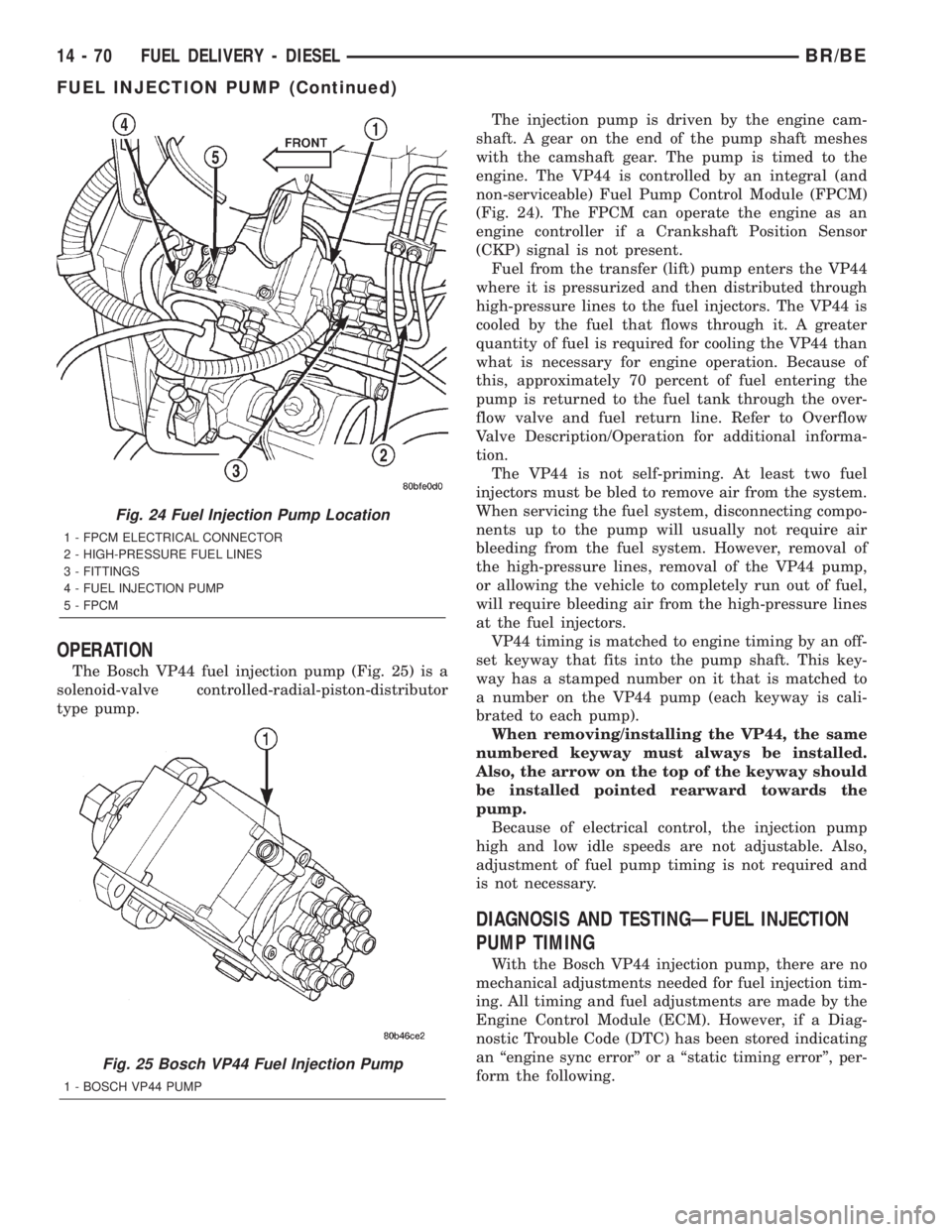
The Bosch VP44 fuel injection pump (Fig. 25) is a
solenoid-valve controlled-radial-piston-distributor
type pump.The injection pump is driven by the engine cam-
shaft. A gear on the end of the pump shaft meshes
with the camshaft gear. The pump is timed to the
engine. The VP44 is controlled by an integral (and
non-serviceable) Fuel Pump Control Module (FPCM)
(Fig. 24). The FPCM can operate the engine as an
engine controller if a Crankshaft Position Sensor
(CKP) signal is not present.
Fuel from the transfer (lift) pump enters the VP44
where it is pressurized and then distributed through
high-pressure lines to the fuel injectors. The VP44 is
cooled by the fuel that flows through it. A greater
quantity of fuel is required for cooling the VP44 than
what is necessary for engine operation. Because of
this, approximately 70 percent of fuel entering the
pump is returned to the fuel tank through the over-
flow valve and fuel return line. Refer to Overflow
Valve Description/Operation for additional informa-
tion.
The VP44 is not self-priming. At least two fuel
injectors must be bled to remove air from the system.
When servicing the fuel system, disconnecting compo-
nents up to the pump will usually not require air
bleeding from the fuel system. However, removal of
the high-pressure lines, removal of the VP44 pump,
or allowing the vehicle to completely run out of fuel,
will require bleeding air from the high-pressure lines
at the fuel injectors.
VP44 timing is matched to engine timing by an off-
set keyway that fits into the pump shaft. This key-
way has a stamped number on it that is matched to
a number on the VP44 pump (each keyway is cali-
brated to each pump).
When removing/installing the VP44, the same
numbered keyway must always be installed.
Also, the arrow on the top of the keyway should
be installed pointed rearward towards the
pump.
Because of electrical control, the injection pump
high and low idle speeds are not adjustable. Also,
adjustment of fuel pump timing is not required and
is not necessary.
DIAGNOSIS AND TESTINGÐFUEL INJECTION
PUMP TIMING
With the Bosch VP44 injection pump, there are no
mechanical adjustments needed for fuel injection tim-
ing. All timing and fuel adjustments are made by the
Engine Control Module (ECM). However, if a Diag-
nostic Trouble Code (DTC) has been stored indicating
an ªengine sync errorº or a ªstatic timing errorº, per-
form the following.
Fig. 24 Fuel Injection Pump Location
1 - FPCM ELECTRICAL CONNECTOR
2 - HIGH-PRESSURE FUEL LINES
3 - FITTINGS
4 - FUEL INJECTION PUMP
5 - FPCM
Fig. 25 Bosch VP44 Fuel Injection Pump
1 - BOSCH VP44 PUMP
14 - 70 FUEL DELIVERY - DIESELBR/BE
FUEL INJECTION PUMP (Continued)
Page 1381 of 2255
CAUTION: Be sure that the high-pressure fuel lines
are installed in the same order that they were
removed.
(1) Lubricate threads of injector line fittings with
clean engine oil.
(2) Loosen, but do not remove, all fuel line support
bracket bolts.
(3) Installrearinjection line bundle beginning
with cylinder head (fuel injector) connections, fol-
lowed by injection pump connections. Tighten all fit-
tings finger tight.
(4) Tighten fittings at fuel injector ends for cylin-
ders number 6 and 5 to 38 N´m (28 ft. lbs.) torque.
Do not tighten number 3 line at this time. It
will be tightened during bleeding procedure.
(5) Tighten 3 fittings at fuel injection pump ends
to 24 N´m (18 ft. lbs.) torque.
(6) Installfrontinjection line bundle beginning
with cylinder head (fuel injector) connections, fol-
lowed by injection pump connections. Tighten all fit-
tings finger tight.
(7) Tighten fitting at fuel injector end for cylinder
number 2 to 38 N´m (28 ft. lbs.) torque.Do not
tighten lines number 1 or 4 at this time. They
will be tightened during bleeding procedure.
(8) Tighten remaining 3 fittings at fuel injection
pump ends to 24 N´m (18 ft. lbs.) torque.
(9) Install fuel line support bracket bolts to intake
manifold and tighten to 24 N´m (18 ft. lbs.) torque.
CAUTION: Be sure fuel lines are not contacting
each other or any other component. Noise will
result.
(10) Install engine lifting bracket at rear of intake
manifold. Tighten 2 bolts to 77 N´m (57 ft. lbs.)
torque.
(11) Install cable bracket housing/cable assembly
and tighten 3 mounting bolts to 24 N´m (18 ft. lbs.)
torque.
(12) Clean any old gasket material below and
above intake manifold air heater element block. Also
clean mating areas at intake manifold and air intake
housing.
(13) Using new gaskets, position intake manifold
air heater element block to engine.
(14) Install air intake housing and position ground
cable. Install 4 mounting bolts and tighten to 24 N´m
(18 ft. lbs.) torque.
(15) Install air tube (intake manifold-to-charge air
cooler) (Fig. 49). Tighten clamps to 8 N´m (72 in. lbs.)
torque.
(16) Install engine oil dipstick tube support mount-
ing bolt and tighten to 24 N´m (18 ft. lbs.) torque.
(17) Install engine oil dipstick to engine.(18) Connect 2 electrical cables to cable mounting
studs.
(19) Connect electrical connector to bottom of
APPS by pushing connector upward until it snaps
into position.
(20) Connect wiring harness (clip) at bottom of
Accelerator Pedal Position Sensor (APPS) mounting
bracket (Fig. 48).
(21) Connect front wiring clip (Fig. 49) to cable
bracket housing.
(22) Install cable cover (Fig. 47).
(23) Connect both negative battery cables to both
batteries.
(24) Bleed air from fuel system. Do this at fuel
injector ends of lines. Use cylinders numbers 1, 3 and
4 for bleeding. (Refer to 14 - FUEL SYSTEM/FUEL
DELIVERY - STANDARD PROCEDURE). After
bleeding, tighten fittings to 38 N´m (28 ft. lbs.)
torque.
(25) Check lines/fittings for leaks.
FUEL TANK
DESCRIPTION - DIESEL FUEL TANK
The fuel tank is similar to the tank used with gas-
oline powered models. The tank is equipped with a
separate fuel return line and a different fuel tank
module for diesel powered models. A fuel tank
mounted, electric fuel pump is not used with diesel
powered models. Refer to Fuel Tank Module for addi-
tional information.
For removal and installation procedures, refer to
Fuel Tank - Gasoline Engines.
FUEL TANK MODULE
DESCRIPTION
An electric fuel pump isnot usedin the fuel tank
module for diesel powered engines. Fuel is supplied
by the engine mounted fuel transfer pump and the
fuel injection pump.
The fuel tank module is installed in the top of the
fuel tank (Fig. 56). The fuel tank module (Fig. 56)
contains the following components:
²Fuel reservoir
²A separate in-tank fuel filter
²Rollover valve
²Fuel gauge sending unit (fuel level sensor)
²Fuel supply line connection
²Fuel return line connection
²Auxiliary non-pressurized fuel supply fitting
OPERATION
Refer to Fuel Gauge Sending Unit.
14 - 82 FUEL DELIVERY - DIESELBR/BE
FUEL LINES (Continued)
Page 1389 of 2255
REMOVAL
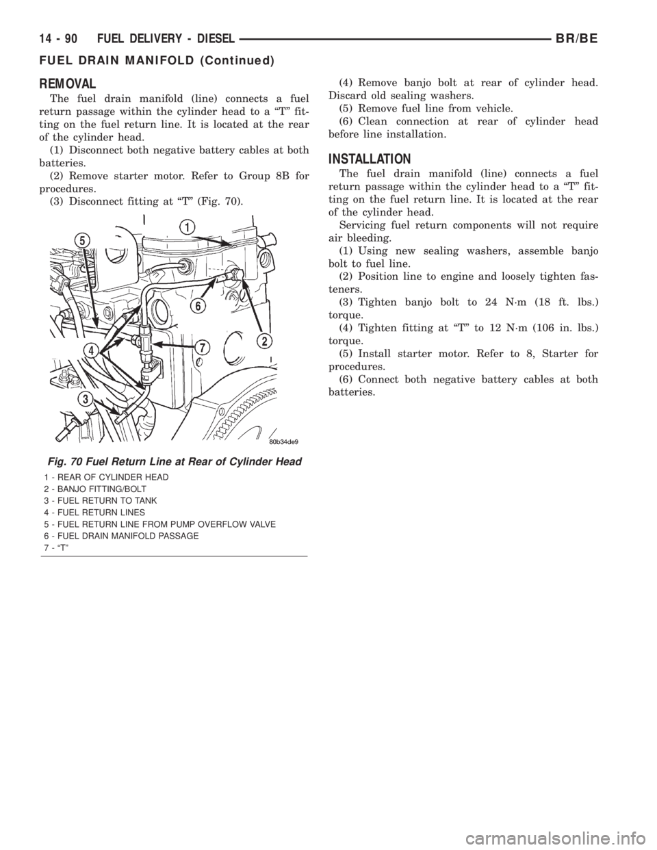
The fuel drain manifold (line) connects a fuel
return passage within the cylinder head to a ªTº fit-
ting on the fuel return line. It is located at the rear
of the cylinder head.
(1) Disconnect both negative battery cables at both
batteries.
(2) Remove starter motor. Refer to Group 8B for
procedures.
(3) Disconnect fitting at ªTº (Fig. 70).(4) Remove banjo bolt at rear of cylinder head.
Discard old sealing washers.
(5) Remove fuel line from vehicle.
(6) Clean connection at rear of cylinder head
before line installation.
INSTALLATION
The fuel drain manifold (line) connects a fuel
return passage within the cylinder head to a ªTº fit-
ting on the fuel return line. It is located at the rear
of the cylinder head.
Servicing fuel return components will not require
air bleeding.
(1) Using new sealing washers, assemble banjo
bolt to fuel line.
(2) Position line to engine and loosely tighten fas-
teners.
(3) Tighten banjo bolt to 24 N´m (18 ft. lbs.)
torque.
(4) Tighten fitting at ªTº to 12 N´m (106 in. lbs.)
torque.
(5) Install starter motor. Refer to 8, Starter for
procedures.
(6) Connect both negative battery cables at both
batteries.
Fig. 70 Fuel Return Line at Rear of Cylinder Head
1 - REAR OF CYLINDER HEAD
2 - BANJO FITTING/BOLT
3 - FUEL RETURN TO TANK
4 - FUEL RETURN LINES
5 - FUEL RETURN LINE FROM PUMP OVERFLOW VALVE
6 - FUEL DRAIN MANIFOLD PASSAGE
7 - ªTº
14 - 90 FUEL DELIVERY - DIESELBR/BE
FUEL DRAIN MANIFOLD (Continued)
Page 1398 of 2255
lines before opening up any fuel system component.
Always cover or cap any open fuel connections before
a fuel system repair is performed.
Each fuel injector connector tube contains an edge
filter (Fig. 13) that breaks up small contaminants
that enter the injector. The edge filter uses the injec-
tors pulsating high-pressure to break up most parti-
cles so they are small enough to pass through the
injector.The edge filters are not a substitute for
proper cleaning and covering of all fuel system
components during repair.
The bottom of each fuel injector is sealed to the
cylinder head with a1.5mmthick copper shim (gas-
ket) (Fig. 12). The correct thickness shim must
always be re-installed after removing an injector.
Fuel pressure in the injector circuit decreases after
injection. The injector needle valve is immediately
closed by the needle valve spring and fuel flow into
the combustion chamber is stopped. Exhaust gases
are prevented from entering the injector nozzle by
the needle valve.
DIAGNOSIS AND TESTINGÐFUEL INJECTOR
TEST
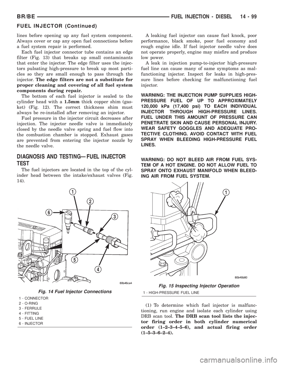
The fuel injectors are located in the top of the cyl-
inder head between the intake/exhaust valves (Fig.
14).A leaking fuel injector can cause fuel knock, poor
performance, black smoke, poor fuel economy and
rough engine idle. If fuel injector needle valve does
not operate properly, engine may misfire and produce
low power.
A leak in injection pump-to-injector high-pressure
fuel line can cause many of same symptoms as mal-
functioning injector. Inspect for leaks in high-pres-
sure lines before checking for malfunctioning fuel
injector.
WARNING: THE INJECTION PUMP SUPPLIES HIGH-
PRESSURE FUEL OF UP TO APPROXIMATELY
120,000 kPa (17,400 psi) TO EACH INDIVIDUAL
INJECTOR THROUGH HIGH-PRESSURE LINES.
FUEL UNDER THIS AMOUNT OF PRESSURE CAN
PENETRATE SKIN AND CAUSE PERSONAL INJURY.
WEAR SAFETY GOGGLES AND ADEQUATE PRO-
TECTIVE CLOTHING. AVOID CONTACT WITH FUEL
SPRAY WHEN BLEEDING HIGH-PRESSURE FUEL
LINES.
WARNING: DO NOT BLEED AIR FROM FUEL SYS-
TEM OF A HOT ENGINE. DO NOT ALLOW FUEL TO
SPRAY ONTO EXHAUST MANIFOLD WHEN BLEED-
ING AIR FROM FUEL SYSTEM.
(1) To determine which fuel injector is malfunc-
tioning, run engine and isolate each cylinder using
DRB scan tool.The DRB scan tool lists the injec-
tor firing order in both cylinder numerical
order (1±2±3±4±5±6), and actual firing order
(1±5±3±6±2±4).
Fig. 14 Fuel Injector Connections
1 - CONNECTOR
2 - O-RING
3 - FERRULE
4 - FITTING
5 - FUEL LINE
6 - INJECTOR
Fig. 15 Inspecting Injector Operation
1 - HIGH-PRESSURE FUEL LINE
BR/BEFUEL INJECTION - DIESEL 14 - 99
FUEL INJECTOR (Continued)
Page 1617 of 2255
FRONT SERVO
DESCRIPTION
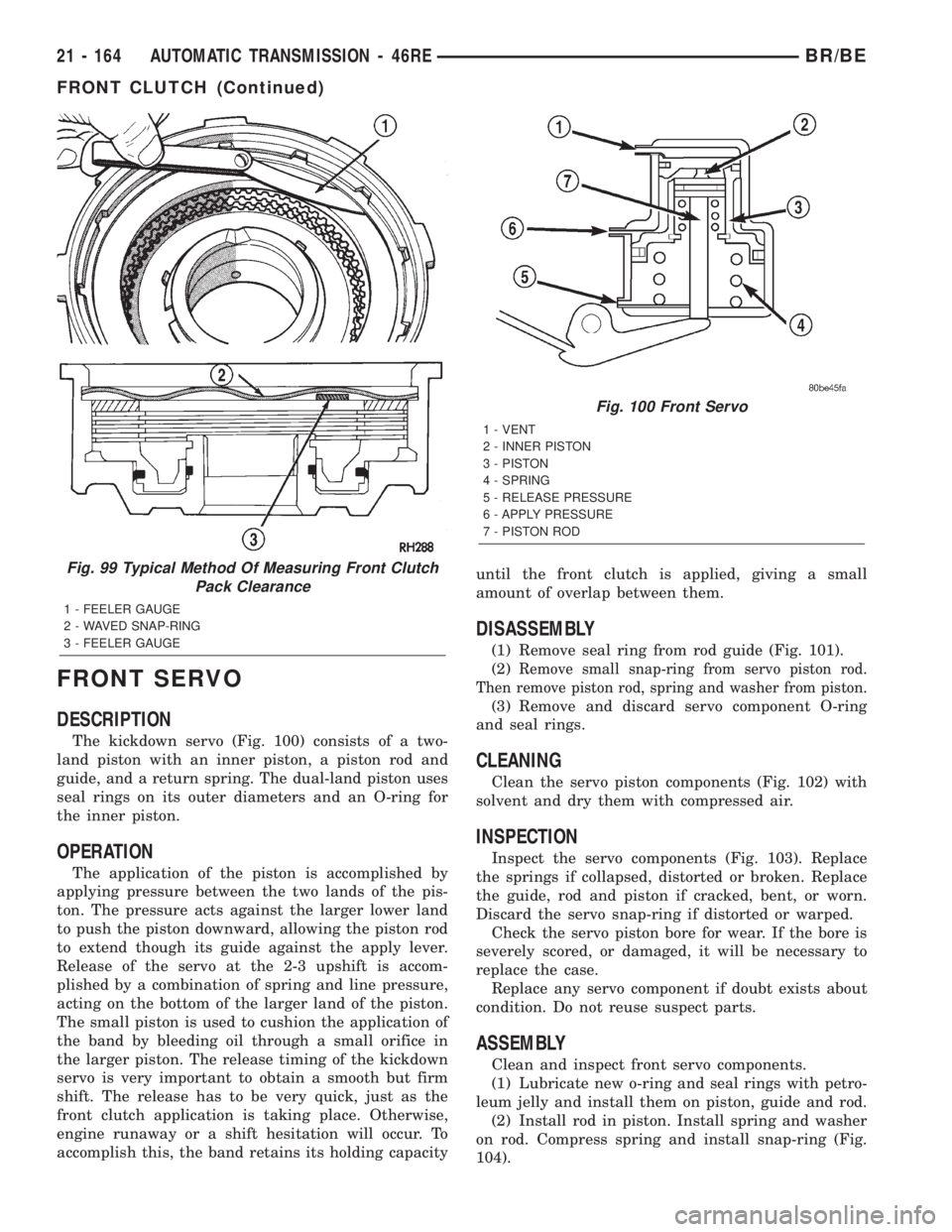
The kickdown servo (Fig. 100) consists of a two-
land piston with an inner piston, a piston rod and
guide, and a return spring. The dual-land piston uses
seal rings on its outer diameters and an O-ring for
the inner piston.
OPERATION
The application of the piston is accomplished by
applying pressure between the two lands of the pis-
ton. The pressure acts against the larger lower land
to push the piston downward, allowing the piston rod
to extend though its guide against the apply lever.
Release of the servo at the 2-3 upshift is accom-
plished by a combination of spring and line pressure,
acting on the bottom of the larger land of the piston.
The small piston is used to cushion the application of
the band by bleeding oil through a small orifice in
the larger piston. The release timing of the kickdown
servo is very important to obtain a smooth but firm
shift. The release has to be very quick, just as the
front clutch application is taking place. Otherwise,
engine runaway or a shift hesitation will occur. To
accomplish this, the band retains its holding capacityuntil the front clutch is applied, giving a small
amount of overlap between them.
DISASSEMBLY
(1) Remove seal ring from rod guide (Fig. 101).
(2)
Remove small snap-ring from servo piston rod.
Then remove piston rod, spring and washer from piston.
(3) Remove and discard servo component O-ring
and seal rings.
CLEANING
Clean the servo piston components (Fig. 102) with
solvent and dry them with compressed air.
INSPECTION
Inspect the servo components (Fig. 103). Replace
the springs if collapsed, distorted or broken. Replace
the guide, rod and piston if cracked, bent, or worn.
Discard the servo snap-ring if distorted or warped.
Check the servo piston bore for wear. If the bore is
severely scored, or damaged, it will be necessary to
replace the case.
Replace any servo component if doubt exists about
condition. Do not reuse suspect parts.
ASSEMBLY
Clean and inspect front servo components.
(1) Lubricate new o-ring and seal rings with petro-
leum jelly and install them on piston, guide and rod.
(2) Install rod in piston. Install spring and washer
on rod. Compress spring and install snap-ring (Fig.
104).
Fig. 99 Typical Method Of Measuring Front Clutch
Pack Clearance
1 - FEELER GAUGE
2 - WAVED SNAP-RING
3 - FEELER GAUGE
Fig. 100 Front Servo
1 - VENT
2 - INNER PISTON
3 - PISTON
4 - SPRING
5 - RELEASE PRESSURE
6 - APPLY PRESSURE
7 - PISTON ROD
21 - 164 AUTOMATIC TRANSMISSION - 46REBR/BE
FRONT CLUTCH (Continued)