2002 DODGE RAM tow
[x] Cancel search: towPage 14 of 2255

LUBRICATION & MAINTENANCE
TABLE OF CONTENTS
page page
INTERNATIONAL SYMBOLS
DESCRIPTION...........................1
PARTS & LUBRICANT RECOMMENDATION
STANDARD PROCEDURE
STANDARD PROCEDURE -
CLASSIFICATION OF LUBRICANTS..........1
FLUID TYPES
DESCRIPTION...........................2
OPERATION.............................6
FLUID CAPACITIES
SPECIFICATIONS.........................6
MAINTENANCE SCHEDULES
DESCRIPTION...........................7JUMP STARTING
STANDARD PROCEDURE
STANDARD PROCEDURE - JUMP
STARTING.............................7
HOISTING
STANDARD PROCEDURE
STANDARD PROCEDURE - HOISTING.......9
TOWING
STANDARD PROCEDURE
STANDARD PROCEDURE - TOWING.......10
INTERNATIONAL SYMBOLS
DESCRIPTION
DaimlerChrysler Corporation uses international
symbols to identify engine compartment lubricant
and fluid inspection and fill locations (Fig. 1).
PARTS & LUBRICANT
RECOMMENDATION
STANDARD PROCEDURE - CLASSIFICATION OF
LUBRICANTS
Only lubricants that are endorsed by the following
organization should be used to service a
DaimlerChrysler Corporation vehicle.²Society of Automotive Engineers (SAE)
²American Petroleum Institute (API) (Fig. 6)
²National Lubricating Grease Institute (NLGI)
(Fig. 2)
Lubricating grease is rated for quality and usage
by the NLGI. All approved products have the NLGI
symbol (Fig. 2) on the label. At the bottom NLGI
symbol is the usage and quality identification letters.
Wheel bearing lubricant is identified by the letter
ªGº. Chassis lubricant is identified by the latter ªLº.
The letter following the usage letter indicates the
quality of the lubricant. The following symbols indi-
cate the highest quality.
When service is required, DaimlerChrysler Corpo-
ration recommends that only Mopartbrand parts,
lubricants and chemicals be used. Mopar provides
the best engineered products for servicing
DaimlerChrysler Corporation vehicles.
Fig. 1 International SymbolsFig. 2 NLGI Symbol
1 - WHEEL BEARINGS
2 - CHASSIS LUBRICATION
3 - CHASSIS AND WHEEL BEARINGS
BR/BELUBRICATION & MAINTENANCE 0 - 1
Page 23 of 2255

TOWING
STANDARD PROCEDURE - TOWING
A vehicle equipped with SAE approved sling-type
towing equipment can be used to tow all vehicles.
When towing a 4WD vehicle using a wheel-lift towing
device, use tow dollies under the opposite end of the
vehicle. A vehicle with flat-bed device can also be
used to transport a disabled vehicle (Fig. 12).
A wooden crossbeam may be required for proper
connection when using the sling-type, front-end tow-
ing method.
SAFETY PRECAUTIONS
CAUTION: The following safety precautions must be
observed when towing a vehicle:
²Secure loose and protruding parts.
²Always use a safety chain system that is inde-
pendent of the lifting and towing equipment.
²Do not allow towing equipment to contact the
disabled vehicle's fuel tank.
²Do not allow anyone under the disabled vehicle
while it is lifted by the towing device.
²Do not allow passengers to ride in a vehicle
being towed.
²Always observe state and local laws regarding
towing regulations.
²Do not tow a vehicle in a manner that could
jeopardize the safety of the operator, pedestrians or
other motorists.²Do not attach tow chains, T-hooks, J-hooks, or a
tow sling to a bumper, steering linkage, drive shafts
or a non-reinforced frame hole.
²Do not tow a heavily loaded vehicle. Damage to
the cab, cargo box or frame may result. Use a flatbed
device to transport a loaded vehicle.
GROUND CLEARANCE
CAUTION: If vehicle is towed with wheels removed,
install lug nuts to retain brake drums or rotors.
A towed vehicle should be raised until lifted wheels
are a minimum 100 mm (4 in) from the ground. Be
sure there is adequate ground clearance at the oppo-
site end of the vehicle, especially when towing over
rough terrain or steep rises in the road. If necessary,
remove the wheels from the lifted end of the vehicle
and lower the vehicle closer to the ground, to
increase the ground clearance at the opposite end of
the vehicle. Install lug nuts on wheel attaching studs
to retain brake drums or rotors.
RAMP ANGLE
If a vehicle with flat-bed towing equipment is used,
the approach ramp angle should not exceed 15
degrees.
Fig. 11 Front Lift Pad Location
1 - SHIPPING TIE DOWN SLOT
2 - CROSSMEMBER BOLT ACCESS HOLE
3 - LIFTARM
4 - LIFT PAD EXTENSION
5 - FRAME RAIL
Fig. 12 Tow Vehicles With Approved Equipment
1 - SLING TYPE
2 - WHEEL LIFT
3 - FLAT BED
0 - 10 LUBRICATION & MAINTENANCEBR/BE
HOISTING (Continued)
Page 24 of 2255

TOWING WHEN KEYS ARE NOT AVAILABLE
When the vehicle is locked and keys are not avail-
able, use a flat bed hauler. A Wheel-lift or Sling-type
device can be used on 4WD vehicles providedall the
wheels are lifted off the ground using tow dol-
lies.
FOUR-WHEEL-DRIVE VEHICLE TOWING
Chrysler Corporation recommends that a vehicle be
transported on a flat-bed device. A Wheel-lift or
Sling-type device can be used providedall the
wheels are lifted off the ground using tow dol-
lies.WARNING: WHEN TOWING A DISABLED VEHICLE
AND THE DRIVE WHEELS ARE SECURED IN A
WHEEL LIFT OR TOW DOLLIES, ENSURE THE
TRANSMISSION IS IN THE PARK POSITION (AUTO-
MATIC TRANSMISSION) OR A FORWARD DRIVE
GEAR (MANUAL TRANSMISSION).
CAUTION: Many vehicles are equipped with air
dams, spoilers, and/or ground effect panels. To
avoid component damage, a wheel-lift towing vehi-
cle or a flat-bed hauling vehicle is recommended.
BR/BELUBRICATION & MAINTENANCE 0 - 11
TOWING (Continued)
Page 28 of 2255

STANDARD PROCEDURE
STANDARD PROCEDURES - ALIGNMENT I.F.S.
Before each alignment reading the vehicle should
be jounced (rear first, then front). Grasp each
bumper at the center and jounce the vehicle up and
down several times. Always release the bumper in
the down position.Set the front end alignment to
specifications while the vehicle is in its NOR-
MALLY LOADED CONDITION.
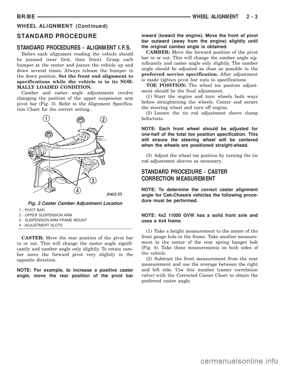
Camber and caster angle adjustments involve
changing the position of the upper suspension arm
pivot bar (Fig. 3). Refer to the Alignment Specifica-
tion Chart for the correct setting.
CASTER:Move the rear position of the pivot bar
in or out. This will change the caster angle signifi-
cantly and camber angle only slightly. To retain cam-
ber move the forward pivot very slightly in the
opposite direction.
NOTE: For example, to increase a positive caster
angle, move the rear position of the pivot barinward (toward the engine). Move the front of pivot
bar outward (away from the engine) slightly until
the original camber angle is obtained.
CAMBER:Move the forward position of the pivot
bar in or out. This will change the camber angle sig-
nificantly and caster angle only slightly. The camber
angle should be adjusted as close as possible to the
preferred service specification. After adjustment
is made tighten pivot bar nuts to specifications.
TOE POSITION:The wheel toe position adjust-
ment should be the final adjustment.
(1) Start the engine and turn wheels both ways
before straightening the wheels. Center and secure
the steering wheel and turn off engine.
(2) Loosen the tie rod adjustment sleeve clamp
bolts/nuts.
NOTE: Each front wheel should be adjusted for
one-half of the total toe position specification. This
will ensure the steering wheel will be centered
when the wheels are positioned straight-ahead.
(3) Adjust the wheel toe position by turning the tie
rod adjustment sleeves as necessary.
STANDARD PROCEDURE - CASTER
CORRECTION MEASUREMENT
NOTE: To determine the correct caster alignment
angle for Cab-Chassis vehicles the following proce-
dure must be performed.
NOTE: 4x2 11000 GVW has a solid front axle and
uses a 4x4 frame.
(1) Take a height measurement to the center of the
front gauge hole in the frame. Take another measure-
ment to the center of the rear spring hanger bolt
(Fig. 4). Take these measurements on both sides of
the vehicle.
(2) Subtract the front measurement from the rear
measurement and use the average between the right
and left side. Use this number (caster correlation
valve) with the Corrected Caster Chart to obtain the
preferred caster angle.
Fig. 3 Caster Camber Adjustment Location
1 - PIVOT BAR
2 - UPPER SUSPENSION ARM
3 - SUSPENSION ARM FRAME MOUNT
4 - ADJUSTMENT SLOTS
BR/BEWHEEL ALIGNMENT 2 - 3
WHEEL ALIGNMENT (Continued)
Page 79 of 2255

(11) Push and hold differential case to ring gear
side of the housing and record the dial indicator
reading (Fig. 15).
(12) Add 0.38 mm (0.015 in.) to the zero end play
total. This total represents the thickness of shims
needed to preload the new bearings when the differ-
ential is installed.
(13) Rotate dial indicator out of the way on the
pilot stud.
(14) Remove differential case and dummy bearings
from the housing.
(15) Install the pinion gear in the housing. Install
the pinion yoke and establish the correct pinion
rotating torque.
(16) Install differential case and dummy bearings
D-343 in the housing (without shims), install bearing
caps and tighten bolts snug.
(17) Seat ring gear side dummy bearing (Fig. 12).
(18) Position dial indicator plunger on a flat sur-
face between the ring gear bolt heads (Fig. 13).
(19) Push and hold differential case toward pinion
gear and zero the dial indicator (Fig. 16).
(20) Push and hold differential case to ring gear
side of the housing and record dial indicator reading
(Fig. 17). This is the shim thickness needed on the
ring gear side of the differential case for proper back-
lash.
(21) Subtract the backlash shim thickness from
the total preload shim thickness. The remainder is
the shim thickness required on the pinion side of the
housing.
(22) Rotate dial indicator out of the way on pilot
stud.
(23) Remove differential case and dummy bearings
from the housing.(24) Install selected side bearing shims onto the
differential case hubs.
(25) Install side bearings on differential case hubs
with Install C-4487-1 and Handle C-4171.
(26) Install bearing cups on differential.
(27) Install Spreader W-129-B and some items
from Adapter Set 6987 on the housing and spread
open enough to receive differential case.
Fig. 15 DIFFERENTIAL CASE RING GEAR SIDE
1 - DIAL INDICATOR
2 - DIFFERENTIAL CASE TO RING GEAR SIDE
3 - DIFFERENTIAL HOUSING
Fig. 16 DIFFERENTIAL CASE PINION GEAR SIDE
1 - DIAL INDICATOR FACE
2 - DIFFERENTIAL CASE TO PINION GEAR SIDE
3 - PINION GEAR
4 - DIFFERENTIAL HOUSING
5 - DIFFERENTIAL CASE
Fig. 17 DIFFERENTIAL CASE RING GEAR SIDE
1 - DIAL INDICATOR
2 - DIFFERENTIAL CASE TO RING GEAR SIDE
3 - PINION GEAR
4 - DIFFERENTIAL HOUSING
5 - DIFFERENTIAL CASE
3 - 24 FRONT AXLE - 248FBIBR/BE
FRONT AXLE - 248FBI (Continued)
Page 80 of 2255

CAUTION: Never spread housing over 0.50 mm
(0.020 in.). The housing can be damaged if over-
spread.
(28) Install differential case into the housing.
(29) Remove spreader from the housing.
(30) Rotate differential case several times to seat
the side bearings.
(31) Position indicator plunger against a ring gear
tooth (Fig. 18).
(32) Push and hold ring gear upward while not
allowing the pinion gear to rotate.
(33) Zero dial indicator face to pointer.
(34) Push and hold ring gear downward while not
allowing the pinion gear to rotate. Dial indicator
reading should be between 0.12 mm (0.005 in.) and
0.20 mm (0.008 in.). If backlash is not within specifi-
cations transfer the necessary amount of shim thick-
ness from one side of the housing to the other (Fig.
19).
(35) Verify differential case and ring gear runout
by measuring ring to pinion gear backlash at eight
locations around the ring gear. Readings should not
vary more than 0.05 mm (0.002 in.). If readings vary
more than specified, the ring gear or the differential
case is defective.
After the proper backlash is achieved, perform
Gear Contact Pattern Analysis procedure.
GEAR CONTACT PATTERN
The ring and pinion gear contact patterns will
show if the pinion depth is correct. It will also show
if the ring gear backlash has been adjusted correctly.
The backlash can be adjusted within specifications to
achieve desired tooth contact patterns.
(1) Apply a thin coat of hydrated ferric oxide or
equivalent to the drive and coast side of the ring gear
teeth.
(2) Wrap, twist and hold a shop towel around the
pinion yoke to increase the turning resistance of the
pinion. This will provide a more distinct contact pat-
tern.
(3) With a boxed end wrench on the ring gear bolt,
rotate the differential case one complete revolution in
both directions while a load is being applied from
shop towel.
The areas on the ring gear teeth with the greatest
degree of contact against the pinion teeth will squee-
gee the compound to the areas with the least amount
of contact. Note and compare patterns on the ring
gear teeth to Gear Tooth Contact Patterns chart (Fig.
20)and adjust pinion depth and gear backlash as nec-
essary.
Fig. 18 RING GEAR BACKLASH
1 - DIAL INDICATOR
Fig. 19 BACKLASH SHIM
BR/BEFRONT AXLE - 248FBI 3 - 25
FRONT AXLE - 248FBI (Continued)
Page 89 of 2255

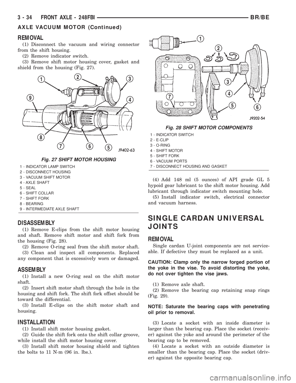
REMOVAL
(1) Disconnect the vacuum and wiring connector
from the shift housing.
(2) Remove indicator switch.
(3) Remove shift motor housing cover, gasket and
shield from the housing (Fig. 27).
DISASSEMBLY
(1) Remove E-clips from the shift motor housing
and shaft. Remove shift motor and shift fork from
the housing (Fig. 28).
(2) Remove O-ring seal from the shift motor shaft.
(3) Clean and inspect all components. Replaced
any component that is excessively worn or damaged.
ASSEMBLY
(1) Install a new O-ring seal on the shift motor
shaft.
(2) Insert shift motor shaft through the hole in the
housing and shift fork. The shift fork offset should be
toward the differential.
(3) Install E-clips on the shift motor shaft and
housing.
INSTALLATION
(1) Install shift motor housing gasket.
(2) Guide the shift fork onto the shift collar groove,
while install the shift motor housing cover.
(3) Install shift motor housing shield and tighten
the bolts to 11 N´m (96 in. lbs.).(4) Add 148 ml (5 ounces) of API grade GL 5
hypoid gear lubricant to the shift motor housing. Add
lubricant through indicator switch mounting hole.
(5) Install indicator switch, electrical connector
and vacuum harness.
SINGLE CARDAN UNIVERSAL
JOINTS
REMOVAL
Single cardan U-joint components are not service-
able. If defective they must be replaced as a unit.
CAUTION: Clamp only the narrow forged portion of
the yoke in the vise. To avoid distorting the yoke,
do not over tighten the vise jaws.
(1) Remove axle shaft.
(2) Remove the bearing cap retaining snap rings
(Fig. 29).
NOTE: Saturate the bearing caps with penetrating
oil prior to removal.
(3) Locate a socket with an inside diameter is
larger than the bearing cap. Place the socket (receiv-
er) against the yoke and around the perimeter of the
bearing cap to be removed.
(4) Locate a socket with an outside diameter is
smaller than the bearing cap. Place the socket (driv-
er) against the opposite bearing cap.
Fig. 27 SHIFT MOTOR HOUSING
1 - INDICATOR LAMP SWITCH
2 - DISCONNECT HOUSING
3 - VACUUM SHIFT MOTOR
4 - AXLE SHAFT
5 - SEAL
6 - SHIFT COLLAR
7 - SHIFT FORK
8 - BEARING
9 - INTERMEDIATE AXLE SHAFT
Fig. 28 SHIFT MOTOR COMPONENTS
1 - INDICATOR SWITCH
2 - E-CLIP
3 - O-RING
4 - SHIFT MOTOR
5 - SHIFT FORK
6 - VACUUM PORTS
7 - DISCONNECT HOUSING AND GASKET
3 - 34 FRONT AXLE - 248FBIBR/BE
AXLE VACUUM MOTOR (Continued)
Page 110 of 2255

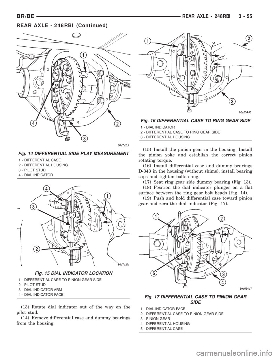
(13) Rotate dial indicator out of the way on the
pilot stud.
(14) Remove differential case and dummy bearings
from the housing.(15) Install the pinion gear in the housing. Install
the pinion yoke and establish the correct pinion
rotating torque.
(16) Install differential case and dummy bearings
D-343 in the housing (without shims), install bearing
caps and tighten bolts snug.
(17) Seat ring gear side dummy bearing (Fig. 13).
(18) Position the dial indicator plunger on a flat
surface between the ring gear bolt heads (Fig. 14).
(19) Push and hold differential case toward pinion
gear and zero the dial indicator (Fig. 17).
Fig. 14 DIFFERENTIAL SIDE PLAY MEASUREMENT
1 - DIFFERENTIAL CASE
2 - DIFFERENTIAL HOUSING
3 - PILOT STUD
4 - DIAL INDICATOR
Fig. 15 DIAL INDICATOR LOCATION
1 - DIFFERENTIAL CASE TO PINION GEAR SIDE
2 - PILOT STUD
3 - DIAL INDICATOR ARM
4 - DIAL INDICATOR FACE
Fig. 16 DIFFERENTIAL CASE TO RING GEAR SIDE
1 - DIAL INDICATOR
2 - DIFFERENTIAL CASE TO RING GEAR SIDE
3 - DIFFERENTIAL HOUSING
Fig. 17 DIFFERENTIAL CASE TO PINION GEAR
SIDE
1 - DIAL INDICATOR FACE
2 - DIFFERENTIAL CASE TO PINION GEAR SIDE
3 - PINION GEAR
4 - DIFFERENTIAL HOUSING
5 - DIFFERENTIAL CASE
BR/BEREAR AXLE - 248RBI 3 - 55
REAR AXLE - 248RBI (Continued)