Page 2677 of 4323
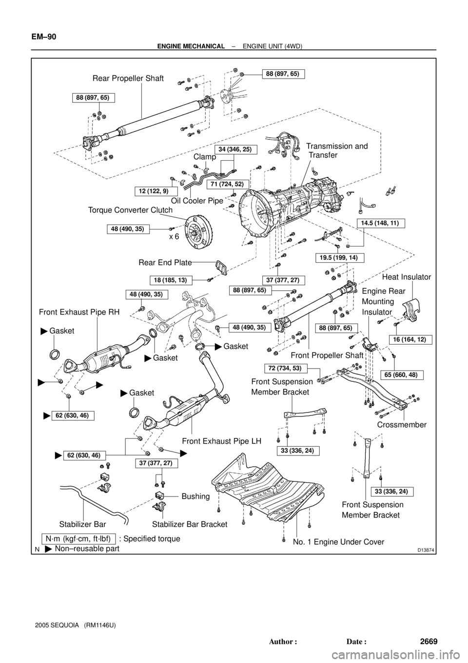
D13874
N´m (kgf´cm, ft´lbf) : Specified torque
�Non±reusable part
37 (377, 27)
Stabilizer Bar
Bushing
Stabilizer Bar Bracket
No. 1 Engine Under Cover
18 (185, 13)
Rear End Plate
Torque Converter Clutch
x 6
48 (490, 35)
Oil Cooler Pipe
34 (346, 25)
Gasket �
Front Exhaust Pipe RH
48 (490, 35)
Gasket �
� Gasket
37 (377, 27)
Crossmember
Engine Rear
Mounting
Insulator
19.5 (199, 14)
14.5 (148, 11)
Transmission and
Transfer
88 (897, 65)
Rear Propeller Shaft88 (897, 65)
Front Propeller Shaft
Heat Insulator
Front Exhaust Pipe LH
Clamp
71 (724, 52)
� Gasket
48 (490, 35)
16 (164, 12)
65 (660, 48)
88 (897, 65)
88 (897, 65)
72 (734, 53)
Front Suspension
Member Bracket
33 (336, 24)
Front Suspension
Member Bracket
33 (336, 24)
��
�62 (630, 46)
�62 (630, 46)�
12 (122, 9)
EM±90
± ENGINE MECHANICALENGINE UNIT (4WD)
2669 Author�: Date�:
2005 SEQUOIA (RM1146U)
Page 2886 of 4323
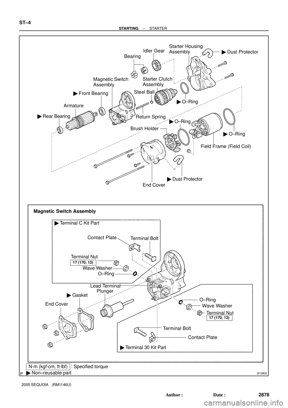
B13802
� O±Ring Idler GearStarter Housing
Assembly
Return SpringStarter Clutch
Assembly
Steel Ball
Contact Plate � Rear BearingArmatureMagnetic Switch
AssemblyBearing
� Front Bearing
� O±Ring
End Cover
Brush Holder
Magnetic Switch Assembly
Terminal Nut
O±Ring Wave WasherTerminal Bolt
� Terminal C Kit Part
Lead Terminal
Plunger
� Gasket
End Cover
Terminal BoltWave Washer O±Ring
Terminal Nut
� Terminal 30 Kit Part
� Non±reusable part
� Dust Protector
� Dust Protector
Field Frame (Field Coil)
17 (170, 13)
17 (170, 13)
N´m (kgf´cm, ft´lbf) : Specified torque� O±Ring
Contact Plate
ST±4
± STARTINGSTARTER
2878 Author�: Date�:
2005 SEQUOIA (RM1146U)
Page 2888 of 4323
(3)
(1) (4)
(5)
ST0948
Magnetic Finger
ST±6
± STARTINGSTARTER
2880 Author�: Date�:
2005 SEQUOIA (RM1146U)
DISASSEMBLY
1. REMOVE FIELD FRAME AND ARMATURE
(a")
ST090±06
B12318
B12328
B13804
B13805
(2)(3)
(1) (4)
(5)
ST0948
Magnetic Finger
ST±6
± STARTINGSTARTER
2880 Author�: Date�:
2005 SEQUOIA (RM1146U)
DISASSEMBLY
1. REMOVE FIELD FRAME AND ARMATURE
(a) Remove the nut, and disconnect the lead wire from the
magnetic switch terminal.
Torque: 5.9 N´m (60 kgf´cm, 52 in.´lbf)
(b) Remove the 2 through bolts.
Torque: 9.3 N´m (95 kgf´cm, 82 in.´lbf)
(c) Pull out the field frame together with the armature from the
magnetic switch assembly.
NOTICE:
At the time of assembly, align the protrusion of the field
frame with the groove of the magnetic switch.
(d) Remove the O±ring from the field frame.
HINT:
At the time of assembly, use a new O±ring.
2. REMOVE STARTER HOUSING, CLUTCH ASSEMBLY
AND GEAR
(a) Remove the 2 screws.
Torque: 9.3 N´m (95 kgf´cm, 82 in.´lbf)
(b) Remove these parts from the magnetic switch assembly:
(1) Starter housing
(2) Return spring
(3) Idler gear
(4) Bearing
(5) Starter clutch assembly
HINT:
At the time of assembly, please refer to the following items.
Apply grease to the return spring and insert the return spring
into the clutch shaft hole.
3. REMOVE STEEL BALL
Using a magnetic finger, remove the steel ball from the clutch
shaft hole.
HINT:
At the time of assembly, apply grease to the steel ball and insert
the steel ball into the clutch shaft hole.
Page 2892 of 4323

P21088
Ohmmeter
No Continuity
P10821
Free
Lock
B12319
Terminal CTerminal 50
ContinuityOhmmeter
B12320ContinuityOhmmeter
Terminal 50
ST±10
± STARTINGSTARTER
2884 Author�: Date�:
2005 SEQUOIA (RM1146U)
12. INSPECT BRUSH HOLDER INSULATION
Using an ohmmeter, check that there is no continuity between
the positive (+) and negative (±) brush holders.
If there is continuity, repair or replace the brush holder.
13. INSPECT GEAR TEETH
Check the gear teeth on the pinion gear, idle gear and the clutch
assembly for wear or damage.
If any damage is found, replace the gear or clutch assembly,
and also check the drive plate ring gear for wear or damage.
14. INSPECT CLUTCH PINION GEAR
Rotate the pinion gear clockwise, and check that it turns freely.
Check that it locks by rotating the pinion gear counterclockwise.
If necessary, replace the clutch assembly.
15. INSPECT FRONT AND REAR BEARING
Turn the bearing by hand as applying inward force.
If resistance is felt or the bearing sticks, replace the bearing.
16. DO PULL±IN COIL OPEN CIRCUIT TEST
Using an ohmmeter, check that there is continuity between ter-
minals 50 and C.
If there is no continuity, replace the magnetic switch.
17. DO HOLDING COIL OPEN CIRCUIT TEST
Using an ohmmeter, check that there is continuity between ter-
minal 50 and the switch body.
If there is no continuity, replace the magnetic switch.
Page 2897 of 4323

ST094±06
B02289
Terminal 50
Battery Terminal C
B02290
Battery Terminal CDisconnect
B02291
Disconnect
Battery
B02292
Terminal 30
Battery Ammeter Terminal 50
± STARTINGSTARTER
ST±15
2889 Author�: Date�:
2005 SEQUOIA (RM1146U)
TEST
NOTICE:
These tests must be done within 3 to 5 seconds to avoid the
coil to be burned ± out.
1. DO PULL±IN TEST
(a) Disconnect the field coil lead wire from terminal C.
(b) Connect the battery to the magnetic switch as shown.
Check that the pinion gear moves outward.
2. DO HOLDING TEST
While connected as above with the pinion gear out, disconnect
the negative (±) lead from terminal C. Check that the pinion gear
remains out.
3. INSPECT CLUTCH PINION GEAR RETURN
Disconnect the negative (±) lead from the starter body. Check
that the pinion gear returns inward.
4. DO NO±LOAD PERFORMANCE TEST
(a) Connect the battery and ammeter to the starter as shown.
(b) Check that the starter rotates smoothly and steadily with
the pinion gear moving out. Check that the ammeter
shows the specified current.
Specified current:
At 11.5 V: 100 A or less
Page 2918 of 4323
AT131±01
D14123
Clutch No.2 (C2) Clutch No.3 (C
3)
Clutch No.1 (C
1)One±way Clutch
No.1 (F1)
One±way Clutch
No.2 (F
2)
Brake No.3
(B
3)
Brake No.1 (B1)
Brake No.2 (B2)One±way Clutch
No.3 (F
3)Brake No.4 (B4)
Shift Solenoid Valve SLT
Shift Solenoid Valve SL1Shift Solenoid Valve S1
Shift Solenoid Valve S2Shift Solenoid Valve SR Shift Solenoid Valve SL2Shift Solenoid Valve SLU
AT±2
± AUTOMATIC TRANSMISSION (A750E, A750F)AUTOMATIC TRANSMISSION SYSTEM
2910 Author�: Date�:
2005 SEQUOIA (RM1146U)
OPERATION
Page 2926 of 4323
VALVE BODY ASSEMBLY
2918 Author�: Date�:
2005 SEQUOIA (RM1146U)
VALVE BOD")
D13867
AT136±01
D13866
AT0103
D12703
D12704
Orange
Blue
Clamp
ClampBolt
Bolt AT±10
± AUTOMATIC TRANSMISSION (A750E, A750F)VALVE BODY ASSEMBLY
2918 Author�: Date�:
2005 SEQUOIA (RM1146U)
VALVE BODY ASSEMBLY
ON±VEHICLE REPAIR
1. DRAIN AUTOMATIC TRANSMISSION FLUID
(a) Remove the drain plug and gasket, and drain the ATF.
(b) Install a new gasket and the drain plug.
Torque: 20 N´m (204 kgf´cm, 15 ft´lbf)
2. REMOVE OIL PAN
NOTICE:
Some fluid will remain in the oil pan.
(a) Remove the 20 bolts.
(b) Remove the oil pan gasket.
3. EXAMINE PARTICLES IN PAN
Remove the magnets and use them to collect any steel par-
ticles. Carefully look at the foreign matter and particles in the
pan and on the magnets to anticipate the type of wear you will
find in the transmission.
Steel (magnetic) ... bearing, gear and clutch plate wear
Brass (non±magnetic) ... bushing wear
4. REMOVE OIL STRAINER
Remove the 4 bolts, the oil strainer and the O±ring.
NOTICE:
Be careful as some fluid will come out with the oil strainer.
5. REMOVE ATF TEMPERATURE SENSOR
(a) Disconnect the 7 solenoid valve connectors.
(b) Remove the 2 bolts, clamps and ATF temperature sen-
sors.
Page 2939 of 4323
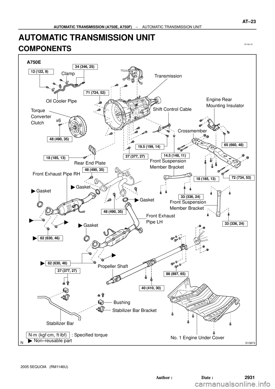
AT13E±01
D13873
A750E
Clamp
Oil Cooler Pipe34 (346, 25)
Torque
Converter
Clutchx6
Transmission
48 (490, 35)
71 (724, 52)
Front Exhaust Pipe RH
N´m (kgf´cm, ft´lbf) : Specified torque
�Non±reusable part
37 (377, 27)
Stabilizer BarBushing
Stabilizer Bar Bracket
No. 1 Engine Under Cover
40 (410, 30)
88 (897, 65)
18 (185, 13)
CrossmemberEngine Rear
Mounting Insulator
Shift Control Cable
37 (377, 27)
Gasket �
Front Exhaust
Pipe LH
Rear End Plate
18 (185, 13)
Gasket �
�62 (630, 46)
� �
62 (630, 46)
�
� Gasket
Propeller Shaft
19.5 (199, 14)
14.5 (148, 11)
65 (660, 48)
72 (734, 53)
33 (336, 24)
33 (336, 24)
�
� Gasket
48 (490, 35)
Front Suspension
Member Bracket Front Suspension
Member Bracket
12 (122, 9)
48 (490, 35)
± AUTOMATIC TRANSMISSION (A750E, A750F)AUTOMATIC TRANSMISSION UNIT
AT±23
2931 Author�: Date�:
2005 SEQUOIA (RM1146U)
AUTOMATIC TRANSMISSION UNIT
COMPONENTS
 Clutch No.3 (C
3)
Clutch No.1 (C
1)One±way Clutch
No.1 (F1)
One±way Clutch
No.2 (F
2)
Brake No.3
(B
3)
Brake No.1 (B1)
Brake No.2 (B2)One±way Clutch
No.3 (F
3)Brak")