Page 2974 of 4323
F19280
F19281
F19282
SST
F19283
TR±28
± TRANSFERREAR OUTPUT SHAFT
2966 Author�: Date�:
2005 SEQUOIA (RM1146U)
5. REMOVE FRONT DRIVE CLUTCH SLEEVE
(a) Using a screwdriver, remove the 2 shifting key springs.
(b) Remove the 3 shifting keys.
(c) Remove the front drive clutch sleeve.
6. REMOVE SYNCHRONIZER RING SET
7. REMOVE DRIVE SPROCKET
(a) Using SST and a press, remove the output shaft rear ra-
dial ball bearing.
SST 09555±55010
(b) Remove the output shaft spacer No. 1 and drive sprocket.
(c) Remove the output shaft plate washer and drive sprocket
bearing.
Page 2975 of 4323

INSPECTION
1. INSPECT OUTPUT SHAFT REAR
Using a micrometer, measure the outer diameter")
TR0DI±01
F19284
A B C D
F19286
± TRANSFERREAR OUTPUT SHAFT
TR±29
2967 Author�: Date�:
2005 SEQUOIA (RM1146U)
INSPECTION
1. INSPECT OUTPUT SHAFT REAR
Using a micrometer, measure the outer diameter of the output
shaft rear journal surface.
Standard diameter:
Part A: 27.98 to 27.99 mm (1.1016 to 1.1020 in.)
Part B: 31.98 to 32.00 mm (1.2591 to 1.2598 in.)
Part C: 34.98 to 35.00 mm (1.3772 to 1.3780 in.)
Part D: 36.98 to 37.00 mm (1.4559 to 1.4567 in.)
Minimum diameter:
Part A: 27.98 mm (1.1016 in.)
Part B: 31.98 mm (1.2591 in.)
Part C: 34.98 mm (1.3772 in.)
Part D: 36.98 mm (1.4559 in.)
If the outer diameter is less than the minimum, replace the out-
put shaft rear.
2. INSPECT FRONT DRIVE CLUTCH SLEEVE AND
GEAR SHIFT FORK NO. 1 CLEARANCE
(a) Using vernier calipers, measure the thickness of the gear
shift fork No. 1 claw.
Thickness: 10 mm (0.3937 in.)
(b) Using vernier calipers, measure the width of the groove
of the front drive clutch sleeve.
Width: 10.5 mm (0.4134 in.)
(c) Calculate the clearance between the front drive clutch
sleeve and gear shift fork No. 1.
Standard clearance:
0.26 to 0.84 mm (0.0102 to 0.0331 in.)
Maximum clearance:
0.84 mm (0.0331 in.)
If the clearance exceeds the maximum, replace the front drive
clutch sleeve or gear shift fork No. 1.
Page 2976 of 4323

3. INSPECT HIGH AND LOW CLUTCH SLEEVE AND
GEAR SHIFT FORK NO. 2 CLEARANCE
(a) Using vernier calip")
F19285
F19288
F19287
TR±30
± TRANSFERREAR OUTPUT SHAFT
2968 Author�: Date�:
2005 SEQUOIA (RM1146U)
3. INSPECT HIGH AND LOW CLUTCH SLEEVE AND
GEAR SHIFT FORK NO. 2 CLEARANCE
(a) Using vernier calipers, measure the thickness of the gear
shift fork No. 2 claw.
Thickness: 10 mm (0.3937 in.)
(b) Using vernier calipers, measure the width of the groove
of the high and low clutch sleeve.
Width: 10.5 mm (0.4134 in.)
(c) Calculate the clearance between the high and low clutch
sleeve and gear shift fork No. 1.
Standard clearance:
0.26 to 0.84 mm (0.0102 to 0.0331 in.)
Maximum clearance:
0.84 mm (0.0331 in.)
If the clearance exceeds the maximum, replace the high and
low clutch sleeve or gear shift fork No. 2.
4. INSPECT CENTER DIFFERENTIAL CASE AND FRONT
DRIVE CLUTCH SLEEVE
(a) Check that the tip of the spline gear of the front drive
clutch sleeve is not worn.
(b) Install the front drive clutch sleeve to the center differen-
tial case and check that the front drive clutch sleeve
moves smoothly.
5. INSPECT CENTER DIFFERENTIAL CASE AND HIGH
AND LOW CLUTCH SLEEVE
(a) Check that the tip of the spline gear of the front drive
clutch sleeve is not worn.
(b) Install the front drive clutch sleeve to the center differen-
tial case and check that the front drive clutch sleeve
moves smoothly.
Page 2977 of 4323
TR0DJ±01
F19283
F19751
SST
Groove
F19281
F19293
F19294
± TRANSFERREAR OUTPUT SHAFT
TR±31
2969 Author�: Date�:
2005 SEQUOIA (RM1146U)
REASSEMBLY
1. INSTALL DRIVE SPROCKET
(a) Install the output shaft plate washer and drive sprocket
bearing to the output shaft rear.
(b) Install the drive sprocket and output shaft spacer No. 1 to
the output shaft rear.
(c) Using SST and a press, install a new output shaft rear ra-
dial ball bearing.
SST 09316±60011 (09316±00011, 09316±00071)
NOTICE:
Install the output shaft rear radial ball bearing so that the
groove for the snap ring does not face the drive sprocket.
2. INSTALL SYNCHRONIZER RING SET
3. INSTALL FRONT DRIVE CLUTCH SLEEVE
4. INSTALL CLUTCH HUB
(a) Install the 3 shifting keys to the clutch hub.
(b) Install the 2 shifting key springs to the clutch hub.
NOTICE:
Position the shifting key springs so that their end gaps are
not aligned.
Page 2978 of 4323

(c) Install the output shaft plate washer and output shaft front
needle roller bearing to")
F19279
F19278
F19276
F19277
TR±32
± TRANSFERREAR OUTPUT SHAFT
2970 Author�: Date�:
2005 SEQUOIA (RM1146U)
(c) Install the output shaft plate washer and output shaft front
needle roller bearing to the output shaft rear.
(d) Install the clutch hub to the output shaft rear.
5. INSTALL CENTER DIFFERENTIAL CASE
(a) Install the center differential case to the output shaft rear.
(b) Install the ball and output shaft spacer No. 2 to the center
differential case.
(c) Using a snap ring expander, install the snap ring.
6. INSPECT DRIVE SPROCKET THRUST CLEARANCE
Using a feeler gauge, measure the thrust clearance of the drive
sprocket.
Standard clearance:
0.15 to 0.24 mm (0.0059 to 0.0094 in.)
Maximum clearance:
0.24 mm (0.0094 in.)
If the clearance exceeds the maximum, replace the drive
sprocket.
7. INSPECT DRIVE SPROCKET RADIAL CLEARANCE
Using a dial indicator, measure the radial clearance of the drive
sprocket.
Standard clearance:
0.01 to 0.06 mm (0.0004 to 0.0024 in.)
Maximum clearance:
0.06 mm (0.0024 in.)
If the clearance exceeds the maximum, replace the drive
sprocket, output shaft rear or needle roller bearing.
Page 3045 of 4323
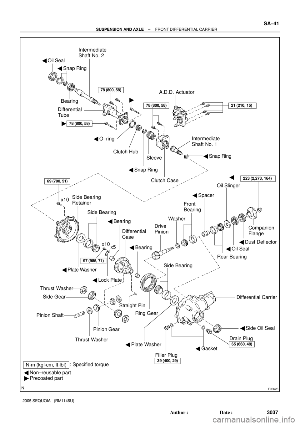
F06628
� Oil Seal
� Snap Ring
Bearing
Intermediate
Shaft No. 2
Differential
Tube
�78 (800, 58)
78 (800, 58)
�
A.D.D. Actuator
21 (210, 15)
� Snap Ring
Intermediate
Shaft No. 1
Clutch Case
Sleeve
� Snap Ring
� O±ring
Clutch Hub
�
Oil Slinger
� Spacer
Companion
Flange
� Dust Deflector
� Oil Seal
Rear Bearing
Washer
Drive
Pinion
Front
Bearing
Differential Carrier
� Side Oil Seal
Drain Plug
65 (660, 48)� Gasket
Filler Plug
39 (400, 29)
Ring Gear
69 (700, 51)
x10Side Bearing
Retainer
Side Bearing
x10
x5
� Plate Washer
97 (985, 71)
� Lock Plate
� Bearing
Differential
Case
� Bearing
Side Bearing
Straight Pin
� Plate Washer
Thrust Washer
Side Gear
Pinion Shaft
Pinion Gear
Thrust Washer
� Non±reusable part
� Precoated part
N´m (kgf´cm, ft´lbf): Specified torque
78 (800, 58)
223 (2,273, 164)
± SUSPENSION AND AXLEFRONT DIFFERENTIAL CARRIER
SA±41
3037 Author�: Date�:
2005 SEQUOIA (RM1146U)
Page 3048 of 4323

6. REMOVE DIFFERENTIAL TUBE
(a) Using a torx so")
R13208
R13209
SST
R13197
SST
SA2349
SST
R11391
SST SA±44
± SUSPENSION AND AXLEFRONT DIFFERENTIAL CARRIER
3040 Author�: Date�:
2005 SEQUOIA (RM1146U)
6. REMOVE DIFFERENTIAL TUBE
(a) Using a torx socket (E14), remove the 4 torx bolts.
(b) Using a plastic hammer, tap on the differential tube to re-
move it.
(c) Remove the sleeve.
(d) Remove the O±ring from the differential tube.
7. REMOVE CLUTCH CASE
(a) Using a torx socket (E14), remove the 2 torx bolts.
(b) Using a plastic hammer, tap on the clutch case to remove
it.
8. REMOVE SIDE OIL SEAL
Using SST, remove the side oil seal.
SST 09308±00010
9. REMOVE INTERMEDIATE SHAFT NO. 1
(a) Using SST, remove the intermediate shaft No. 1.
SST 09350±20015 (09369±20040), 09950±40011
(09951±04010, 09952±04010, 09953±04020,
09954±04010, 09955±04011, 09957±04010,
09958±04011)
(b) Remove the snap ring.
10. REMOVE COMPANION FLANGE
(a) Using a chisel and hammer, unstake the nut.
(b) Using SST to hold the flange, remove the nut.
SST 09330±00021
(c) Using SST, remove the companion flange.
SST 09950±30012 (09951±03010, 09953±03010,
09954±03010, 09955±03030, 09956±03020)
Page 3052 of 4323
SA24R±02
R04465
SST Socket Wrench
R04348
SST
Z03857
R13199
SST
R13422
SA±48
± SUSPENSION AND AXLEFRONT DIFFERENTIAL CARRIER
3044 Author�: Date�:
2005 SEQUOIA (RM1146U)
REPLACEMENT
1. REPLACE COMPANION FLANGE DUST DEFLECTOR,
IF NECESSARY
(a) Using SST, a socket wrench and a press, remove the dust
deflector.
SST 09950±00020
(b) Using SST and a press, install a new dust deflector.
SST 09636±20010
2. REPLACE INTERMEDIATE SHAFT NO. 2, IF NEC-
ESSARY
(a) Remove the clutch hub.
(1) Using a snap ring expander, remove the snap ring.
(2) Remove the clutch hub from the intermediate shaft
No. 2.
(b) Remove the oil seal.
Using SST, remove the oil seal from the tube.
SST 09308±00010
(c) Remove the intermediate shaft No. 2 from the tube.
(1) Using needle nose pliers, remove the snap ring.
(2) Remove the shaft from the tube.
(d) Remove the intermediate shaft No. 2 bearing.
(1) Using a snap ring expander, remove the snap ring.