Page 3793 of 4323
N20013
R±Shape
RotorSnap Ring
Compressor
AC1743
AC1744
AC0950
SST
N20012
R±Shape
Snap Ring
CompressorStator AC±58
± AIR CONDITIONINGCOMPRESSOR AND MAGNETIC CLUTCH
3785 Author�: Date�:
2005 SEQUOIA (RM1146U)
NOTICE:
The snap ring should be installed so that its beveled side
faces up.
(b) Using a plastic hammer, remove the rotor from the shaft.
NOTICE:
Be careful not to damage the pulley when tapping on the ro-
tor.
3. REMOVE STATOR
(a) Disconnect the stator lead wire from the compressor
housing.
(b) Using SST, remove the snap ring.
SST 95994±10020
NOTICE:
The snap ring should be installed so that its beveled side
faces up.
Page 3794 of 4323
AC0951
Stator
± AIR CONDITIONINGCOMPRESSOR AND MAGNETIC CLUTCH
AC±59
3786 Author�: Date�:
2005 SEQUOIA (RM1146U)
(c) Remove the stator.
Page 3795 of 4323
N04963
Dial Indicator
AC1L3±04
AC±60
± AIR CONDITIONINGCOMPRESSOR AND MAGNETIC CLUTCH
3787 Author�: Date�:
2005 SEQUOIA (RM1146U)
REASSEMBLY
Reassembly is in the reverse order of disassembly (See
page AC±57).
AFTER REASSEMBLY, CHECK MAGNETIC CLUTCH
CLEARANCE
(a) Set the dial indicator to the pressure plate of the magnetic
clutch.
(b) Connect the magnetic clutch lead wire to the positive (+)
terminal of the battery.
(c) Check the clearance between the pressure plate and ro-
tor when connecting the negative (±) terminal to the bat-
tery.
Standard clearance:
0.35 to 0.50 mm (0.014 to 0.024 in.)
If the clearance is not within the standard range, adjust the
clearance using shims to obtain the standard clearance.
Standard thickness:
0.1 mm (0.004 in.)
0.3 mm (0.012 in.)
0.5 mm (0.020in.)
Page 3796 of 4323

INSTALLATION
1. INSTALL COMPRESSOR
(a) Install the compressor with the cooler bracket w")
AC3HF±02
± AIR CONDITIONINGCOMPRESSOR AND MAGNETIC CLUTCH
AC±61
3788 Author�: Date�:
2005 SEQUOIA (RM1146U)
INSTALLATION
1. INSTALL COMPRESSOR
(a) Install the compressor with the cooler bracket with the 3 bolts and nut.
Torque:
Bolt: 47 N´m (480 kgf´cm, 35 in.´lbf)
Nut: 25 N´m (255 kgf´cm, 18 in.´lbf)
(b) Connect the connector.
2. CONNECT DISCHARGE AND SUCTION HOSES
Connect both hoses with the 2 nuts.
Torque: 10 N´m (100 kgf´cm, 7 in.´lbf)
NOTICE:
Hoses should be connected immediately after the caps have been removed.
HINT:
Lubricate 2 new O±rings with compressor oil and install them to the hoses.
3. INSTALL AND CHECK DRIVE BELT (See page AC±17, AC±15)
4. CONNECT CABLE TO NEGATIVE BATTERY TERMINAL
5. EVACUATE AIR FROM REFRIGERATION SYSTEM
6. CHARGE SYSTEM WITH REFRIGERANT
Specified amount:
Single A/C: 750 ± 50g (26.45 ± 1.76 oz.)
Dual A/C: 1050 ± 50g (37.03 ± 1.76 oz.)
7. INSPECT FOR LEAKAGE OF REFRIGERANT
Using a gas leak detector, check for leakage of refrigerant.
If there is leakage, check the tightening torque at the joints.
8. PERFORM INITIALIZATION (See page IN±20)
Some systems need initialization when disconnecting the cable from the negative battery terminal.
Page 3830 of 4323
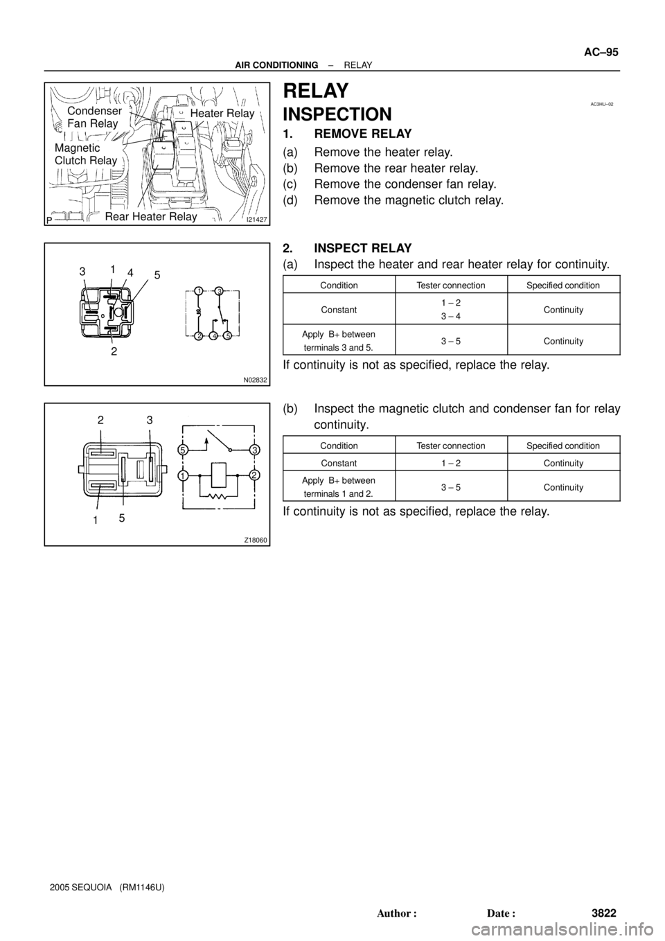
I21427
Heater RelayCondenser
Fan Relay
Magnetic
Clutch Relay
Rear Heater Relay
AC3HU±02
N02832
1
2 3
5
1
23
5
4
4
Z18060
23
15
5
13
2
± AIR CONDITIONINGRELAY
AC±95
3822 Author�: Date�:
2005 SEQUOIA (RM1146U)
RELAY
INSPECTION
1. REMOVE RELAY
(a) Remove the heater relay.
(b) Remove the rear heater relay.
(c) Remove the condenser fan relay.
(d) Remove the magnetic clutch relay.
2. INSPECT RELAY
(a) Inspect the heater and rear heater relay for continuity.
ConditionTester connectionSpecified condition
Constant1 ± 2
3 ± 4Continuity
Apply B+ between
terminals 3 and 5.3 ± 5Continuity
If continuity is not as specified, replace the relay.
(b) Inspect the magnetic clutch and condenser fan for relay
continuity.
ConditionTester connectionSpecified condition
Constant1 ± 2Continuity
Apply B+ between
terminals 1 and 2.3 ± 5Continuity
If continuity is not as specified, replace the relay.