Page 2940 of 4323
D13874
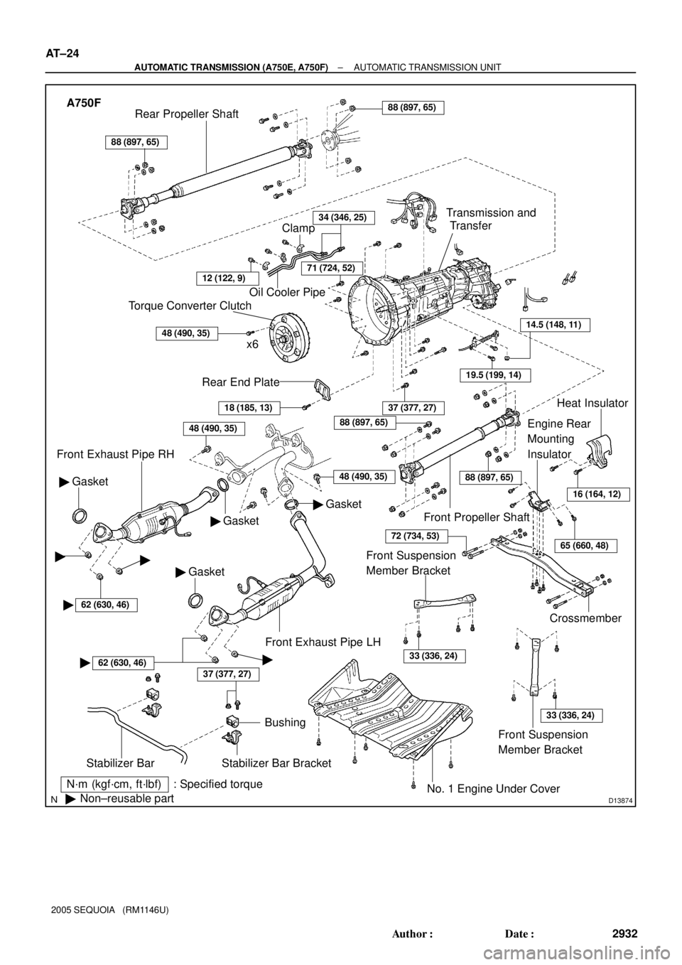
A750F
N´m (kgf´cm, ft´lbf) : Specified torque
�Non±reusable part
37 (377, 27)
Stabilizer Bar
Bushing
Stabilizer Bar Bracket
No. 1 Engine Under Cover
18 (185, 13)
Rear End Plate
Torque Converter Clutch
x6
48 (490, 35)
Oil Cooler Pipe
34 (346, 25)
Gasket �
Front Exhaust Pipe RH
Gasket �
� Gasket
37 (377, 27)
Crossmember
Engine Rear
Mounting
Insulator
19.5 (199, 14)
14.5 (148, 11)
Transmission and
Transfer
88 (897, 65)
Rear Propeller Shaft88 (897, 65)
Front Propeller Shaft
Heat Insulator
Front Exhaust Pipe LH
Clamp
71 (724, 52)
� Gasket
48 (490, 35)
16 (164, 12)
65 (660, 48)
88 (897, 65)
88 (897, 65)
72 (734, 53)
Front Suspension
Member Bracket
33 (336, 24)
Front Suspension
Member Bracket
33 (336, 24)
��
�62 (630, 46)
�62 (630, 46)�
12 (122, 9)
48 (490, 35)
AT±24
± AUTOMATIC TRANSMISSION (A750E, A750F)AUTOMATIC TRANSMISSION UNIT
2932 Author�: Date�:
2005 SEQUOIA (RM1146U)
Page 2943 of 4323
AUTOMATIC TRANSMISSION UNIT
AT±27
2935 Author�: Date�:
2005 SEQUOIA (RM1146U)
13. DISCONNECT OIL COOLER PIPE
(a")
D05186
D13880
SST
F07266
D14215
A750E:
A750F:
± AUTOMATIC TRANSMISSION (A750E, A750F)AUTOMATIC TRANSMISSION UNIT
AT±27
2935 Author�: Date�:
2005 SEQUOIA (RM1146U)
13. DISCONNECT OIL COOLER PIPE
(a) Remove the 3 bolts and clamps.
Torque: 12 N´m (122 kgf´cm, 9 ft´lbf)
(b) Disconnect the 2 oil cooler pipes.
SST 09023±12701
Torque: 34 N´m (346 kgf´cm, 25 ft´lbf)
14. DISCONNECT STABILIZER BAR
(a) Remove the 2 bolts, nuts and stabilizer bar with the bush-
ings and brackets.
Torque: 37 N´m (377 kgf´cm, 27 ft´lbf)
(b) Disconnect the stabilizer bar.
15. REMOVE REAR END PLATE AND TORQUE CON-
VERTER CLUTCH MOUNTING BOLT
(a) Remove the bolt and rear end plate.
Torque: 18 N´m (185 kgf´cm, 13 ft´lbf)
(b) Turn the crankshaft to gain access and remove the 6 bolts
while holding the crankshaft pulley set bolt with a wrench.
Torque: 48 N´m (490 kgf´cm, 35 ft´lbf)
HINT:
At the time of installation, refer to the following:
First install the green colored bolt and then the remaining 5
bolts.
16. JACK UP TRANSMISSION SLIGHTLY
Securely support the transmission on a transmission jack.
Lift the transmission slightly from the crossmember.
Page 2946 of 4323
TORQUE CONVERTER CLUTCH AND DRIVE PLATE
2938 Author�: Date�:
2005 SEQUOIA (RM1146U)
TORQUE CONVE")
AT5436
SST
AT13H±01
AT5437
Hold
Turn
Free
Lock
Q04237
AT±30
± AUTOMATIC TRANSMISSION (A750E, A750F)TORQUE CONVERTER CLUTCH AND DRIVE PLATE
2938 Author�: Date�:
2005 SEQUOIA (RM1146U)
TORQUE CONVERTER CLUTCH
AND DRIVE PLATE
INSPECTION
1. INSPECT ONE±WAY CLUTCH
(a) Install SST so that it fits in the notch of the converter hub
and outer race of the one±way clutch.
SST 09350±30020 (09351±32020)
(b) Press on the serrations of the stator with a finger and ro-
tate it.
(c) Check if it rotates smoothly when turned clockwise and
locks when turned counterclockwise.
If necessary, clean the converter clutch and retest the one±way
clutch.
Replace the converter clutch if the clutch still fails the test.
2. MEASURE DRIVE PLATE RUNOUT AND INSPECT
RING GEAR
(a) Set up a dial indicator and measure the drive plate runout.
Maximum runout: 0.20 mm (0.0079 in.)
(b) Check for damage to the ring gear.
If runout is not within the specification or if the ring gear is dam-
aged, replace the drive plate. If installing a new drive plate, note
the orientation of the spacers and tighten the bolts (See page
EM±83 or EM±95).
Page 2954 of 4323
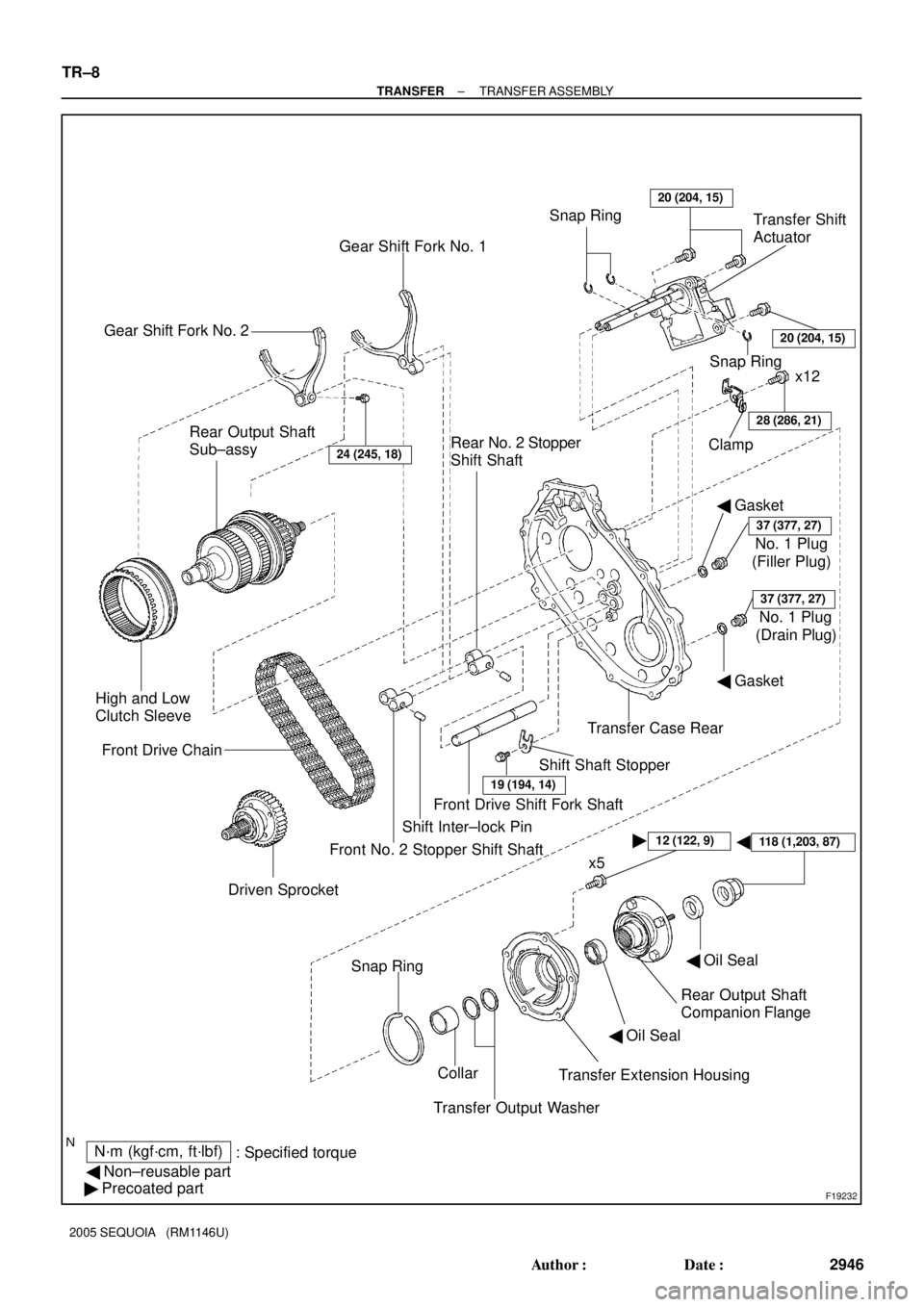
F19232
� �
N´m (kgf´cm, ft´lbf)
: Specified torque
� Non±reusable part
� Precoated partTransfer Extension Housing Collar Snap Ring
Transfer Output WasherRear Output Shaft
Companion Flange
24 (245, 18)
Driven Sprocket Front Drive Chain
19 (194, 14)
Shift Shaft Stopper Rear Output Shaft
Sub±assy
� Gasket
37 (377, 27)
(Filler Plug) Clamp
28 (286, 21)
x12
Gear Shift Fork No. 1
Rear No. 2 Stopper
Shift ShaftSnap RingTransfer Shift
Actuator
� Gasket
� Oil Seal High and Low
Clutch Sleeve
Gear Shift Fork No. 2
x5 Front No. 2 Stopper Shift ShaftShift Inter±lock PinFront Drive Shift Fork ShaftTransfer Case Rear Snap Ring20 (204, 15)
No. 1 Plug
37 (377, 27)
(Drain Plug) No. 1 Plug
� Oil Seal
12 (122, 9)
20 (204, 15)
118 (1,203, 87)
TR±8
± TRANSFERTRANSFER ASSEMBLY
2946 Author�: Date�:
2005 SEQUOIA (RM1146U)
Page 2956 of 4323

6. REMOVE TRANSFER EXTENSION HOUSING
(a) Remove the 5 bolts and transfer extension")
F19242
F19243
F19244
F19245
F19246
TR±10
± TRANSFERTRANSFER ASSEMBLY
2948 Author�: Date�:
2005 SEQUOIA (RM1146U)
6. REMOVE TRANSFER EXTENSION HOUSING
(a) Remove the 5 bolts and transfer extension housing.
HINT:
If necessary, tap on the transfer extension housing with a plas-
tic hammer to remove it.
(b) Using a screwdriver and hammer, remove the oil seal
from the transfer extension housing.
(c) Remove the 2 transfer output washers.
(d) Remove the collar.
7. REMOVE TRANSFER CASE REAR
(a) Remove the 12 bolts and clamp.
(b) Remove the transfer case rear.
HINT:
If necessary, tap on the transfer case rear with a plastic hammer
to remove it.
8. REMOVE GEAR SHIFT FORK NO. 2 AND HIGH AND
LOW CLUTCH SLEEVE
Remove the bolt, gear shift fork No.2 and high and low clutch
sleeve.
9. REMOVE SHIFT SHAFT STOPPER
Remove the bolt and shift shaft stopper.
10. REMOVE FRONT DRIVE SHIFT FORK SHAFT
(a) Turn the front drive shift fork shaft.
(b) Remove the front drive shift fork shaft from the rear case
aligning the cutout with the shift inter±lock pin.
Page 2967 of 4323
F19308
F19306
FIPG
F19244
F19243
F19309
SST
± TRANSFERTRANSFER ASSEMBLY
TR±21
2959 Author�: Date�:
2005 SEQUOIA (RM1146U)
15. INSTALL GEAR SHIFT FORK NO. 2 AND HIGH AND
LOW CLUTCH SLEEVE
(a) Install the gear shift fork No. 2 and high and low clutch
sleeve with the bolt.
Torque: 24 N´m (245 kgf´cm, 18 ft´lbf)
(b) Install the spacer and output shaft front needle roller bear-
ing.
16. INSTALL TRANSFER CASE REAR
(a) Apply FIPG to the transfer case rear, as shown.
FIPG:
Part No. 08826±00090, THREE BOND 1281 or equiva-
lent
(b) Install the clamp and transfer case rear with the
12 bolts.
Torque: 28 N´m (286 kgf´cm, 21 ft´lbf)
17. INSTALL TRANSFER EXTENSION HOUSING
(a) Install the collar and 2 transfer output washers.
(b) Using SST and a hammer, drive in a new oil seal until its
surface is flush with the housing upper surface.
SST 09223±46011, 09631±32020
(c) Coat the lip of the oil seal with MP grease.
Page 2972 of 4323
TR083±03
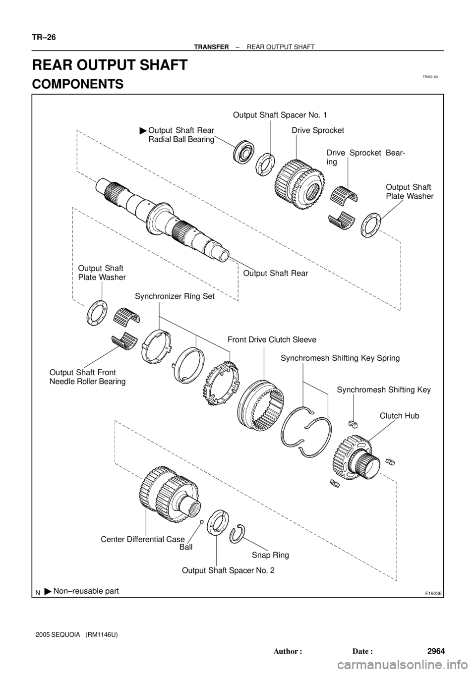
F19236
Output Shaft Rear
Radial Ball Bearing �Output Shaft Spacer No. 1
Output Shaft Front
Needle Roller Bearing
Synchronizer Ring Set
Front Drive Clutch Sleeve
� Non±reusable partCenter Differential Case
Ball
Snap Ring
Output Shaft Spacer No. 2Drive Sprocket
Drive Sprocket Bear-
ing
Output Shaft
Plate Washer
Output Shaft Rear Output Shaft
Plate Washer
Synchromesh Shifting Key Spring
Synchromesh Shifting Key
Clutch Hub
TR±26
± TRANSFERREAR OUTPUT SHAFT
2964 Author�: Date�:
2005 SEQUOIA (RM1146U)
REAR OUTPUT SHAFT
COMPONENTS
Page 2973 of 4323

DISASSEMBLY
1. INSPECT DRIVE SPROCKET THRUST CLEARANCE
Using a feeler gauge, mea")
TR0DH±01
F19276
F19277
F19278
F19279
± TRANSFERREAR OUTPUT SHAFT
TR±27
2965 Author�: Date�:
2005 SEQUOIA (RM1146U)
DISASSEMBLY
1. INSPECT DRIVE SPROCKET THRUST CLEARANCE
Using a feeler gauge, measure the thrust clearance of the drive
sprocket.
Standard clearance:
0.15 to 0.24 mm (0.0059 to 0.0094 in.)
Maximum clearance:
0.24 mm (0.0094 in.)
If the clearance exceeds the maximum, replace the drive
sprocket.
2. INSPECT DRIVE SPROCKET RADIAL CLEARANCE
Using a dial indicator, measure the radial clearance of the drive
sprocket.
Standard clearance:
0.01 to 0.06 mm (0.0004 to 0.0024 in.)
Maximum clearance:
0.06 mm (0.0024 in.)
If the clearance exceeds the maximum, replace the drive
sprocket, output shaft rear or needle roller bearing.
3. REMOVE CENTER DIFFERENTIAL CASE
(a) Using a snap ring expander, remove the snap ring.
(b) Remove the output shaft spacer No. 2 and ball.
(c) Remove the center differential case.
4. REMOVE CLUTCH HUB
Remove the clutch hub, output shaft front needle roller bearing
and output shaft plate washer.