Page 3373 of 4323
RS0BL±11
H23231
RS±82
± SUPPLEMENTAL RESTRAINT SYSTEMAIRBAG SENSOR ASSEMBLY
3365 Author�: Date�:
2005 SEQUOIA (RM1146U)
REMOVAL
NOTICE:
�If the wiring connector of the SRS is disconnected
with the ignition switch in the ON position, DTCs will
be recorded.
�Never use airbag parts from another vehicle. When
replacing parts, replace them with new ones.
1. PRECAUTION (SEE PAGE RS±1 and RS±3)
2. DISCONNECT CABLE FROM NEGATIVE BATTERY
TERMINAL
Wait for 90 seconds after disconnecting the cable to prevent the
airbag working.
�Never reuse an airbag sensor assembly if the airbag
has previously deployed in a collision.
3. REMOVE SHIFTING HOLE COVER (SEE PAGE
BO±89)
4. REMOVE UPPER CONSOLE PANEL (SEE PAGE
BO±89)
5. REMOVE REAR CONSOLE BOX (SEE PAGE
BO±89)
6. REMOVE FRONT CONSOLE BOX (SEE PAGE
BO±89)
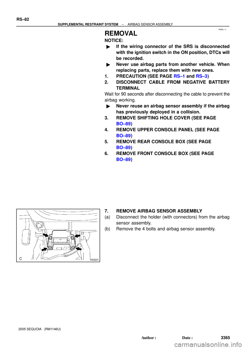
7. REMOVE AIRBAG SENSOR ASSEMBLY
(a) Disconnect the holder (with connectors) from the airbag
sensor assembly.
(b) Remove the 4 bolts and airbag sensor assembly.
Page 3376 of 4323

INSTALLATION
NOTICE:
�Never use SRS parts from another vehicle. When re-
pl")
RS0BO±11
H23231
± SUPPLEMENTAL RESTRAINT SYSTEMAIRBAG SENSOR ASSEMBLY
RS±85
3368 Author�: Date�:
2005 SEQUOIA (RM1146U)
INSTALLATION
NOTICE:
�Never use SRS parts from another vehicle. When re-
placing parts, replace them with new ones.
�Never reuse the airbag sensor assembly involved in
a collision when the airbag has deployed.
�If the airbag sensor assembly center has been
dropped, or there are any cracks, dents or other de-
fects in the case, bracket or connector, replace it with
a new one.
�When installing the airbag sensor assembly center,
be careful that the SRS wiring does not interfere with
other parts and that it is not pinched between other
parts.
�After installing, shake the airbag sensor assembly to
check that there is no looseness.
1. INSTALL AIRBAG SENSOR ASSEMBLY
(a) Install the airbag sensor assembly with the 4 bolts.
Torque: 17.5 N´m (179 kgf´cm, 13 ft´lbf)
(b) Connect the airbag sensor holder (with connectors).
2. INSTALL FRONT CONSOLE BOX ASSEMBLY
(SEE PAGE BO±89)
3. INSTALL REAR CONSOLE BOX ASSEMBLY
(SEE PAGE BO±89)
4. INSTALL UPPER CONSOLE PANEL
(SEE PAGE BO±89)
5. INSTALL SHIFTING HOLE COVER
(SEE PAGE BO±89)
6. CONNECT CABLE TO NEGATIVE BATTERY TERMI-
NAL
7. PERFORM INITIALIZATION (SEE PAGE BE±77)
Some system need initialization when disconnecting the cable
from the negative battery terminal.
8. INSPECT SRS WARNING LIGHT (SEE PAGE DI±1137)
Page 3378 of 4323
RS0TI±03
H23879
± SUPPLEMENTAL RESTRAINT SYSTEMFRONT AIRBAG SENSOR
RS±87
3370 Author�: Date�:
2005 SEQUOIA (RM1146U)
REMOVAL
HINT:
�Use the same procedures for the RH side and LH side.
�The procedures listed below are for the LH side.
NOTICE:
�If the wiring connector of the SRS is disconnected
with the ignition switch in the ON position, DTCs will
be recorded.
�Never use airbag parts from another vehicle. When
replacing parts, replace them with new ones.
�Never reuse a front airbag sensor if the airbag has
previously deployed in a collision.
1. PRECAUTION (SEE PAGE RS±1 and RS±3)
2. DISCONNECT CABLE FROM NEGATIVE BATTERY
TERMINAL
Wait for 90 seconds after disconnecting the cable to prevent the
airbag working.
3. REMOVE FRONT AIRBAG SENSOR LH
(a) Disconnect the front airbag sensor LH connector.
NOTICE:
Disconnect the connector with the sensor assembly
installed.
(b) Remove the 2 nuts and front airbag sensor LH.
Page 3381 of 4323

INSTALLATION
HINT:
�Use the same procedures for the RH side and LH side.
�The")
H23879
RS11I±01
RS±90
± SUPPLEMENTAL RESTRAINT SYSTEMFRONT AIRBAG SENSOR
3373 Author�: Date�:
2005 SEQUOIA (RM1146U)
INSTALLATION
HINT:
�Use the same procedures for the RH side and LH side.
�The procedures listed below are for the LH side.
NOTICE:
�Never use SRS parts from another vehicle. When re-
placing parts, replace them with new ones.
�Never reuse the front airbag sensor involved in a col-
lision when the airbag has deployed.
�If the front airbag sensor center has been dropped, or
there are any cracks, dents or other defects in the
case, bracket or connector, replace it with a new one.
�When installing the front airbag sensor center, be
careful that the SRS wiring does not interfere with
other parts and that it is not pinched between other
parts.
�After installing, shake the front airbag sensor to
check that there is no looseness.
1. INSTALL FRONT AIRBAG SENSORS LH
(a) Install the front airbag sensors LH with the 2 nuts.
Torque: 17.5 N´m (179 kgf´cm, 13 ft´lbf)
(b) Connect the front airbag sensor connectors.
2. CONNECT CABLE TO NEGATIVE BATTERY TERMI-
NAL
3. PERFORM INITIALIZATION (SEE PAGE BE±77)
Some system need initialization when disconnecting the cable
from the negative battery terminal.
4. INSPECT SRS WARNING LIGHT (SEE PAGE DI±1137)
Page 3383 of 4323

REMOVAL
HINT:
�Use the same procedures for the RH side and LH side.
�")
RS11K±01
H20066
RS±92
± SUPPLEMENTAL RESTRAINT SYSTEMSIDE AIRBAG SENSOR ASSEMBLY
3375 Author�: Date�:
2005 SEQUOIA (RM1146U)
REMOVAL
HINT:
�Use the same procedures for the RH side and LH side.
�The procedures listed below are for the LH side.
NOTICE:
�If the wiring connector of the SRS is disconnected
with the ignition switch in the ON position, DTCs will
be recorded.
�Never use airbag parts from another vehicle. When
replacing parts, replace them with new ones.
�Never reuse the side airbag sensor assembly if the
airbag has previously deployed in a collision.
1. PRECAUTION (SEE PAGE RS±1 and RS±3)
2. DISCONNECT CABLE FROM NEGATIVE BATTERY
TERMINAL
Wait for 90 seconds after disconnecting the cable to prevent the
airbag working.
3. REMOVE FRONT DOOR SCUFF PLATE
(SEE PAGE BO±89)
4. REMOVE REAR DOOR SCUFF PLATE
(SEE PAGE BO±89)
5. REMOVE FRONT SEAT OUTER BELT FLOOR AN-
CHOR (SEE PAGE BO±101)
6. REMOVE CENTER PILLAR LOWER GARNISH
(SEE PAGE BO±101)
7. REMOVE FRONT SEAT OUTER BELT RETRACTOR
(SEE PAGE BO±163)
8. REMOVE SIDE AIRBAG SENSOR ASSEMBLY LH
(a) Disconnect the connector from the side airbag sensor as-
sembly LH.
(b) Remove the 3 bolts and the side airbag sensor assembly
LH.
Page 3386 of 4323

INSTALLATION
HINT:
�Use the same procedures for the RH side and LH si")
RS11N±01
H20066
± SUPPLEMENTAL RESTRAINT SYSTEMSIDE AIRBAG SENSOR ASSEMBLY
RS±95
3378 Author�: Date�:
2005 SEQUOIA (RM1146U)
INSTALLATION
HINT:
�Use the same procedures for the RH side and LH side.
�The procedures listed below are for the LH side.
NOTICE:
�Never use SRS parts from another vehicle. When re-
placing parts, replace them with new ones.
�Never reuse the side airbag sensor assembly in-
volved in a collision when the airbag has deployed.
�If the side airbag sensor assembly center has been
dropped, or there are any cracks, dents or other de-
fects in the case, bracket or connector, replace it with
a new one.
�When installing the side airbag sensor assembly, be
careful that the SRS wiring does not interfere with
other parts and that it is not pinched between other
parts.
�After installing, shake the side airbag sensor assem-
bly to check that there is no looseness.
1. INSTALL SIDE AIRBAG SENSOR ASSEMBLY LH
(a) Install the side airbag sensor assembly LH with the 3
bolts.
Torque: 17.5 N´m (179 kgf´cm, 13 ft´lbf)
(b) Connect the connector to the side airbag sensor assem-
bly LH.
2. INSTALL FRONT SEAT OUTER BELT RETRACTOR
(SEE PAGE BO±172)
3. INSTALL CENTER PILLAR LOWER GARNISH
(SEE PAGE BO±108)
4. INSTALL FRONT SEAT OUTER BELT FLOOR AN-
CHOR (SEE PAGE BO±108 )
5. INSTALL REAR DOOR SCUFF PLATE
(SEE PAGE BO±97)
6. INSTALL FRONT DOOR SCUFF PLATE
(SEE PAGE BO±97)
7. CONNECT CABLE TO NEGATIVE BATTERY TERMI-
NAL
8. PERFORM INITIALIZATION (SEE PAGE BE±77)
Some system need initialization when disconnecting the cable
from the negative battery terminal.
9. INSPECT SRS WARNING LIGHT (SEE PAGE DI±1137)
Page 3388 of 4323

REMOVAL
HINT:
�Use the same procedures for the RH side and L")
RS11P±01
H23905
± SUPPLEMENTAL RESTRAINT SYSTEMCURTAIN SHIELD AIRBAG SENSOR ASSEMBLY
RS±97
3380 Author�: Date�:
2005 SEQUOIA (RM1146U)
REMOVAL
HINT:
�Use the same procedures for the RH side and LH side.
�The procedures listed below are for the LH side.
NOTICE:
�If the wiring connector of the SRS is disconnected
with the ignition switch in the ON position, DTCs will
be recorded.
�Never use airbag parts from another vehicle. When
replacing parts, replace them with new ones.
1. PRECAUTION (SEE PAGE RS±1 and RS±3)
2. DISCONNECT CABLE FROM NEGATIVE BATTERY
TERMINAL
Wait for 90 seconds after disconnecting the cable to prevent the
airbag working.
3. REMOVE REAR SEAT NO. 2 ASSEMBLY
(SEE PAGE BO±157)
4. REMOVE REAR DOOR SCUFF PLATE
(SEE PAGE BO±101)
5. REMOVE REAR FLOOR PANEL SUPPORT PLATE
(SEE PAGE BO±101)
6. REMOVE QUARTER TRIM PLATE
(SEE PAGE BO±101)
7. REMOVE CURTAIN SHIELD AIRBAG SENSOR AS-
SEMBLY LH
(a) Disconnect the curtain shield airbag sensor assembly LH
connector.
NOTICE:
Disconnect the connector with the sensor assembly
installed.
(b) Remove the 2 nuts and curtain shield airbag sensor as-
sembly LH.
Page 3391 of 4323

INSTALLATION
HINT:
�Use the same procedures for the RH side")
RS11S±01
H23905
RS±100
± SUPPLEMENTAL RESTRAINT SYSTEMCURTAIN SHIELD AIRBAG SENSOR ASSEMBLY
3383 Author�: Date�:
2005 SEQUOIA (RM1146U)
INSTALLATION
HINT:
�Use the same procedures for the RH side and LH side.
�The procedures listed below are for the LH side.
NOTICE:
�Never use SRS parts from another vehicle. When re-
placing parts, replace them with new ones.
�Never reuse the curtain shield airbag sensor assem-
bly involved in a collision when the airbag has
deployed.
�If the curtain shield airbag sensor assembly center
has been dropped, or there are any cracks, dents or
other defects in the case, bracket or connector, re-
place it with a new one.
�When installing the curtain shield airbag sensor as-
sembly center, be careful that the SRS wiring does
not interfere with other parts and that it is not pinched
between other parts.
�After installing, shake the curtain shield airbag sen-
sor assembly to check that there is no looseness.
1. INSTALL CURTAIN SHIELD AIRBAG SENSOR AS-
SEMBLY LH
(a) Install the curtain shield airbag sensor assembly LH with
the 2 nuts.
Torque:17.5 N´m (179 kgf´cm, 13 ft´lbf)
(b) Connect the curtain shield airbag sensor assembly LH
connector.
2. INSTALL RETRACTOR OF FRONT SEAT OUTER BELT
3. INSTALL QUARTER TRIM PLATE
(SEE PAGE BO±108)
4. INSTALL REAR FLOOR PANEL SUPPORT PLATE
(SEE PAGE BO±108)
5. INSTALL REAR DOOR SCUFF PLATE
(SEE PAGE BO±108)
6. INSTALL REAR SEAT NO. 2 ASSEMBLY
(SEE PAGE BO±158)
7. CONNECT CABLE TO NEGATIVE BATTERY TERMI-
NAL