Page 3789 of 4323

COMPRESSOR AND MAGNETIC
CLUTCH
ON±VEHICLE INSPECTION
1. SET MANIF")
AC1KZ±05
I21361
3
3
I21362
12
AC±54
± AIR CONDITIONINGCOMPRESSOR AND MAGNETIC CLUTCH
3781 Author�: Date�:
2005 SEQUOIA (RM1146U)
COMPRESSOR AND MAGNETIC
CLUTCH
ON±VEHICLE INSPECTION
1. SET MANIFOLD GAUGE SET (See page AC±18)
2. START ENGINE
3. INSPECT COMPRESSOR FOR METALLIC SOUND
Check if a metallic sound can be heard from the compressor
when the A/C switch is on.
If a metallic sound cannot be heard, replace the compressor as-
sembly.
4. INSPECT REFRIGERANT PRESSURE
(See page AC±3)
5. STOP ENGINE
6. INSPECT VISUALLY FOR LEAKAGE OF REFRIGER-
ANT FROM SAFETY SEAL
Using a gas leak detector, check for leakage of refrigerant.
If there is any leakage, replace the compressor assembly.
7. REMOVE MANIFOLD GAUGE SET
(See page AC±19)
8. CHECK FOR LEAKAGE OF GREASE FROM CLUTCH
BEARING
9. CHECK FOR SIGNS OF OIL ON PRESSURE PLATE
If necessary, repair or replace.
10. INSPECT MAGNETIC CLUTCH BEARING FOR NOISE
(a) Start the engine.
(b) Check if abnormal noise is heard from near the compres-
sor when the A/C switch is OFF.
If abnormal noise is being emitted, replace the magnetic clutch.
11. INSPECT MAGNETIC CLUTCH OPERATION
(a) Disconnect the connector.
(b) Connect the positive (+) lead from the battery to terminal
3 and the negative (±) lead to body ground.
(c) Check that the magnetic clutch is energized.
If operation is not as specified, replace the magnetic clutch.
12. INSPECT COMPRESSOR LOCK SENSOR RESIS-
TANCE
(a) Disconnect the connector.
(b) Measure the resistance between terminals 1 and 2.
Standard resistance:
165 to 205 W at 20°C (68°F)
If resistance is not as specified, replace the compressor.
Page 3805 of 4323
AC3I8±02
AC±70
± AIR CONDITIONINGREAR A/C EVAPORATOR
3797 Author�: Date�:
2005 SEQUOIA (RM1146U)
REAR A/C EVAPORATOR
ON±VEHICLE INSPECTION
1. CHECK QUANTITY OF GAS DURING REFRIGERATION CYCLE
2. SET MANIFOLD GAUGE SET (See page AC±18)
3. RUN ENGINE
(a) Rear blower speed set at ºHIº position
(b) A/C switch ON
(c) Rear temperature control set at 18.5°C (65°F)
(d) Run the engine at 1,500 rpm for at least 5 minutes.
Then check that the high pressure reading is 1.9 to 2.1 MPa (19 to 21 kgf/cm
2, 270 to 300 psi).
4. CHECK EXPANSION VALVE
If the expansion valve is faulty, the low pressure reading will drop to 0 kPa (0 kgf/cm
2, 0 psi).
Page 3813 of 4323
AC3HK±02
I21801
COOL
WARM AC±78
± AIR CONDITIONINGWATER VALVE
3805 Author�: Date�:
2005 SEQUOIA (RM1146U)
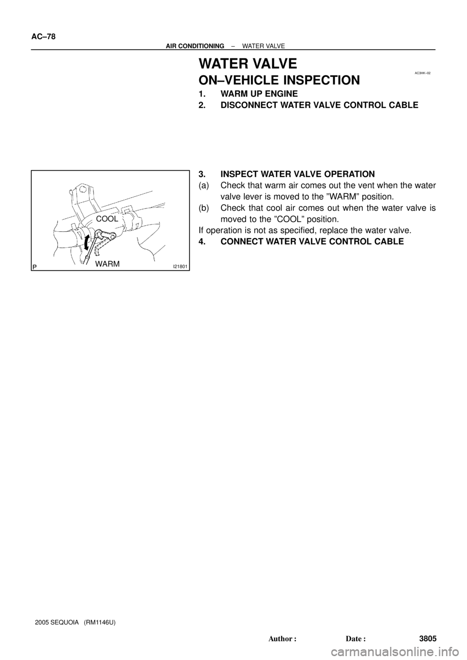
WATER VALVE
ON±VEHICLE INSPECTION
1. WARM UP ENGINE
2. DISCONNECT WATER VALVE CONTROL CABLE
3. INSPECT WATER VALVE OPERATION
(a) Check that warm air comes out the vent when the water
valve lever is moved to the ºWARMº position.
(b) Check that cool air comes out when the water valve is
moved to the ºCOOLº position.
If operation is not as specified, replace the water valve.
4. CONNECT WATER VALVE CONTROL CABLE
Page 3827 of 4323

3,140 kpa 196 kpa
(2.0 kgf/cm
2, 28psi)
OFF (No Continuity)(32.0 kgf/cm2, 455psi)
OFF (No Continuity)
I05079
ON (Co")
I21455
2
13
4
AC1LS±03
Z13470
Low pressure High pressure
side side
ON (Continuity)
3,140 kpa 196 kpa
(2.0 kgf/cm
2, 28psi)
OFF (No Continuity)(32.0 kgf/cm2, 455psi)
OFF (No Continuity)
I05079
ON (Continuity)
1,520 kpa
1,230 kpa
(12.5 kgf/cm
2, 178psi) OFF (No Continuity)
(15.5 kgf/cm
2, 220psi) Cooling Fan Control AC±92
± AIR CONDITIONINGPRESSURE SWITCH
3819 Author�: Date�:
2005 SEQUOIA (RM1146U)
PRESSURE SWITCH
ON±VEHICLE INSPECTION
1. SET MANIFOLD GAUGE SET (See page AC±18)
2. DISCONNECT CONNECTOR
3. RUN ENGINE AT APPROX. 2,000 rpm
4. SET BLOWER SPEED CONTROL SWITCH TO ºHIº
POSITION
5. SET TEMPERATURE CONTROL LEVER TO ºMAX.
COOLº POSITION
6. A/C SWITCH ON
7. INSPECT PRESSURE SWITCH OPERATION
(a) Connect the positive (+) lead from the ohmmeter to termi-
nal 4 and the negative (±) lead to terminal 1.
(b) Check continuity between terminals when refrigerant
pressure is changed, as shown in the illustration.
If operation is not as specified, replace the pressure switch.
8. Cooling fan control:
INSPECT PRESSURE SWITCH OPERATION
9. STOP ENGINE AND REMOVE MANIFOLD GAUGE
SET
10. CONNECT CONNECTOR TO PRESSURE SWITCH
(a) Connect the positive (+) lead from the ohmmeter to termi-
nal 2 and the negative (±) lead to terminal 3.
(b) Check continuity between terminals when refrigerant
pressure is changed, as shown in the illustration.
If operation is not as specified, replace the pressure switch.
11. STOP ENGINE AND REMOVE MANIFOLD GAUGE
SET
12. CONNECT CONNECTOR TO PRESSURE SWITCH
Page 3831 of 4323

CONDENSER FAN
ON±VEHICLE INSPECTION
1. INSPECT CONDENSER FAN OPERATION
Inspect the fan opera")
AC1LZ±05
I21428
1 2
AC±96
± AIR CONDITIONINGCONDENSER FAN
3823 Author�: Date�:
2005 SEQUOIA (RM1146U)
CONDENSER FAN
ON±VEHICLE INSPECTION
1. INSPECT CONDENSER FAN OPERATION
Inspect the fan operation under the following conditions, as
shown in the chart.
Test conditions:
�Start engine
�Blower speed control switch position ºHIº
�Temperature control dial at ºCOOLº position
�Set manifold gauge set
�A/C switch ON
ConditionFan operation (Fan speed)
Refrigerant pressure is less than
1,520 kPa (15.5 kgf/cm2, 220 psi)OFF
Refrigerant pressure is 1,520 kPa
(15.5 kgf/cm2, 220 psi) or aboveRotate
If operation is not as specified, proceed to the next inspection.
2. INSPECT CONDENSER FAN MOTOR OPERATION
(a) Disconnect the fan connector.
(b) Connect the battery and ammeter.
(c) Check that the fan rotates smoothly, and then check the
reading on the ammeter.
Specified amperage: 9.2 to 11.0 A at 20°C (68°F)
If operation is not as specified, replace the fan motor.
If operation is as specified, check the pressure switch, cooling
fan relays and water temp. switch.
Page 3858 of 4323

ix
2005 SEQUOIA from Aug. 04 Prod. (OM34424U)
On±pavement and off±road
driving tips
This vehicle belongs to the utility vehicle class. Utility
vehicles have a significantly")
05_SEQUOIA_U (L/O 0408)
ix
2005 SEQUOIA from Aug. '04 Prod. (OM34424U)
On±pavement and off±road
driving tips
This vehicle belongs to the utility vehicle class. Utility
vehicles have a significantly higher rollover rate than
other types of vehicles. This vehicle will handle and
maneuver differently from an ordinary passenger car be-
cause it is designed for off±road use also. In addition,
this vehicle has a higher ground clearance and center of
gravity than that of an ordinary passenger car. This
vehicle design feature causes this type of vehicle to be
more likely to rollover. Failure to operate this vehicle
correctly may result in loss of control, accidents or
vehicle rollover causing death or serious injury. Be sure
to read ªOff±road vehicle precautionsº on page 334 in
Section 2 and ªOff±road driving precautionsº on page
365 in Section 3.
Leak detection pump
This pump performs fuel evaporation leakage check. This
check is done approximately five hours after the engine is
turned off. So you may hear sound coming from under-
neath the luggage compartment for several minutes. It
does not indicate a malfunction.
Page 4018 of 4323

159
2005 SEQUOIA from Aug. 04 Prod. (OM34424U)
�Idling for a long period with the air
conditioning on in stop±and±go traffic.
�Towing a trailer.
NOTICE
�Do not remove the th")
05_SEQUOIA_U (L/O 0408)
159
2005 SEQUOIA from Aug. '04 Prod. (OM34424U)
�Idling for a long period with the air
conditioning on in stop±and±go traffic.
�Towing a trailer.
NOTICE
�Do not remove the thermostat in
the engine cooling system as this
may cause the engine to overheat.
The thermostat is designed to con-
trol the flow of coolant to keep the
temperature of the engine within
the specified operating range.
�Do not continue driving with an
overheated engine. See ªIf your ve-
hicle overheatsº on page 386 in
Section 4.
Normal
driving
Idling
The oil pressure gauge indicates engine
oil pressure when the ignition switch is
on. Check it while driving to make sure
that the needle is in the proper range.
If the oil pressure should stay below the
normal range, pull off the road to a safe
place and stop the engine immediately.
Call a Toyota dealer or qualified repair
shop for assistance.
Oil pressure may not build up when the
oil level is too low. The oil pressure
gauge is not designed to indicate oil level,
and the oil level must be checked using
the level dipstick.
NOTICE
Do not drive the vehicle with the oil
pressure below the normal range until
the cause is fixedÐit may ruin the
engine.
Oil pressure gauge
Page 4019 of 4323

160
2005 SEQUOIA from Aug. 04 Prod. (OM34424U)
The voltmeter tells whether the battery
is charged or discharged. Check it
while the engine is runningÐthe needle
should always")
05_SEQUOIA_U (L/O 0408)
160
2005 SEQUOIA from Aug. '04 Prod. (OM34424U)
The voltmeter tells whether the battery
is charged or discharged. Check it
while the engine is runningÐthe needle
should always indicate as shown above.
If the needle reads below or above the
normal range while the engine is running,
it indicates the charging system needs im-
mediate repair.
However, it is normal for the needle to
drop below the normal range during en-
gine starting.The tachometer indicates engine speed
in thousands of rpm (revolutions per
minute). Use it while driving to select
correct shift points and to prevent en-
gine lugging and over±revving.
Driving with the engine running too fast
causes excessive engine wear and poor
fuel economy. Remember, in most cases
the slower the engine speed, the greater
the fuel economy.
NOTICE
Do not let the indicator needle get
into the red zone. This may cause
severe engine damage.
This meter displays the odometer and
two trip meters.
1. OdometerÐShows the total distance
the vehicle has been driven.
2. Two trip metersÐShow two different
distances independently driven since
the last time each trip meter was set
to zero.
You can use one trip meter to calculate
the fuel economy and the other to
measure the distance on each trip. All
trip meter data is cancelled if the elec-
trical power source is disconnected.
3. Trip meter reset knobÐResets the two
trip meters to zero, and also change
the meter display.
Voltmeter Tachometer Odometer and two trip meters