Page 3223 of 4323

ABS & VSC ACTUATOR
ON±VEHICLE INSPECTION
1. CONNECT TOYOTA HAND±HELD TES")
TOYOTA
Hand±held
Tester
D05981DLC3
BR1NG±05
BR±48
± BRAKEABS & VSC ACTUATOR
3215 Author�: Date�:
2005 SEQUOIA (RM1146U)
ABS & VSC ACTUATOR
ON±VEHICLE INSPECTION
1. CONNECT TOYOTA HAND±HELD TESTER:
(a) Connect the TOYOTA hand±held tester to the DLC3.
(b) Start the engine and run it at idle.
(c) Select the ACTIVE TEST mode on the TOYOTA hand±
held tester.
HINT:
Please refer to the TOYOTA hand±held tester operator's manu-
al for further details.
2. INSPECT ACTUATOR MOTOR OPERATION
(a) With the motor relay ON, check the actuator motor opera-
tion noise.
(b) Turn the motor relay OFF.
(c) Depress the brake pedal and hold it for about 15 seconds.
Check that the pedal does not go down any further while
holding.
(d) With the motor relay ON, check that the pedal does not
pulsate.
NOTICE:
Do not keep motor relay ON for more than 5 seconds con-
tinuously. When operating it continuously, set the interval
of more than 20 seconds.
(e) Turn the motor relay OFF and release the brake pedal.
3. INSPECT RIGHT FRONT WHEEL OPERATION
NOTICE:
Never turn ON the solenoid which is not described below.
(a) With the brake pedal depressed, perform the following
operations.
(b) Turn the SFRH and SFRR solenoid ON simultaneously,
and check that the pedal cannot be depressed.
NOTICE:
Do not keep solenoid ON for more than 10 seconds contin-
uously. When operating it continuously, set the interval of
more than 20 seconds.
(c) Turn the SFRH and SFRR solenoid OFF simultaneously,
and check that the pedal can be depressed.
(d) Turn the motor relay ON and check that the pedal returns.
NOTICE:
Do not keep motor relay ON for more than 5 seconds con-
tinuously. When operating it continuously, set the interval
of more than 20 seconds.
(e) Turn the motor relay OFF and release the brake pedal.
4. INSPECT OTHER WHEEL OPERATION
As in the same procedure, check the solenoids of other wheels.
HINT:
Left front wheel: SFLH, SFLR
Right rear wheel: SRRH, SRRR
Left rear wheel: SRLH, SRLR
Page 3238 of 4323
P06717
SR1F2±02
P06723
CORRECT WRONG WRONG
± STEERINGDRIVE BELT
SR±3
3230 Author�: Date�:
2005 SEQUOIA (RM1146U)
DRIVE BELT
INSPECTION
INSPECT DRIVE BELT
Visually check the belt for excessive wear, frayed cords, etc.
If any defect has been found, replace the drive belt.
HINT:
Cracks on the rib side of the belt are considered acceptable. If
the missing chunks from the ribs are found on the belt, it should
be replaced.
HINT:
�ºNew beltº refers to a belt which has been used less than
5 minutes on a running engine.
�ºUsed beltº refers to a belt which has been used on a run-
ning engine for 5 minutes or more.
�After installing a belt, check that it fits properly in the
ribbed grooves.
�Check with your hand to confirm that the belt has not
slipped out of the groove on the bottom of the pulley.
�After installing a new belt, run the engine for about 5 min-
utes and recheck the belt tension.
Page 3239 of 4323
SR01V±10
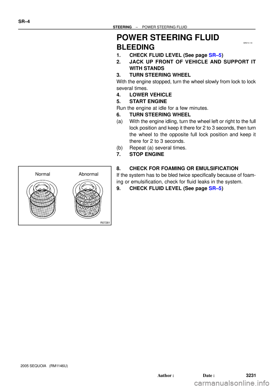
R07281
Normal Abnormal SR±4
± STEERINGPOWER STEERING FLUID
3231 Author�: Date�:
2005 SEQUOIA (RM1146U)
POWER STEERING FLUID
BLEEDING
1. CHECK FLUID LEVEL (See page SR±5)
2. JACK UP FRONT OF VEHICLE AND SUPPORT IT
WITH STANDS
3. TURN STEERING WHEEL
With the engine stopped, turn the wheel slowly from lock to lock
several times.
4. LOWER VEHICLE
5. START ENGINE
Run the engine at idle for a few minutes.
6. TURN STEERING WHEEL
(a) With the engine idling, turn the wheel left or right to the full
lock position and keep it there for 2 to 3 seconds, then turn
the wheel to the opposite full lock position and keep it
there for 2 to 3 seconds.
(b) Repeat (a) several times.
7. STOP ENGINE
8. CHECK FOR FOAMING OR EMULSIFICATION
If the system has to be bled twice specifically because of foam-
ing or emulsification, check for fluid leaks in the system.
9. CHECK FLUID LEVEL (See page SR±5)
Page 3240 of 4323

or less
Engine Idling Engine Stopped
± STEERINGPOWER STEERING FLUID
SR±5
3232 Author�: Date�:
2005 SEQUOIA (RM1146U)
INSPECT")
R00427
HOT
COLD
SR01W±10
R07281
Normal Abnormal
R10552
5 mm (0.20 in.)
or less
Engine Idling Engine Stopped
± STEERINGPOWER STEERING FLUID
SR±5
3232 Author�: Date�:
2005 SEQUOIA (RM1146U)
INSPECTION
1. CHECK FLUID LEVEL
(a) Keep the vehicle level.
(b) With the engine stopped, check the fluid level in the reser-
voir.
If necessary, add fluid.
Fluid: ATF DEXRON® II or III
HINT:
When the fluid is hot, check that the fluid level is within the HOT
range on the reservoir/reservoir cap dipstick.
If the fluid is cold, check that it is within the COLD range.
(c) Start the engine and run at idle.
(d) Turn the steering wheel from the lock position to the other
side of lock position several times to boost fluid tempera-
ture.
Fluid temperature: 80°C (176°F)
(e) Check for foaming or emulsification.
If there is foaming or emulsification, bleed the air from the power
steering system (See page SR±4).
(f) With the engine idling, measure the fluid level in the reser-
voir.
(g) Stop the engine.
(h) Wait a few minutes and remeasure the fluid level in the
reservoir.
Maximum fluid level rise: 5 mm (0.20 in.)
If a problem is found, bleed the air from the power steering sys-
tem (See page SR±4).
(i) Check the fluid level.
Page 3241 of 4323

F13254
INOUTAttachment
Pressure Feed Tube
SST
Z15498
Oil
Reservoir
PS Vane
Pump PS Gear
SST Closed
Z15499
Oil
Reservoir
PS Vane
Pump PS Gear
SST Open SR±6
± STEERINGPOWER STEERING FLUID
3233 Author�: Date�:
2005 SEQUOIA (RM1146U)
2. CHECK STEERING FLUID PRESSURE
(a) Remove the air cleaner assembly with the air cleaner
hose connected (See page SR±26).
(b) Disconnect the pressure feed tube from the PS vane
pump (See page SR±26).
(c) Connect SST, as shown in the illustration.
SST 09640±10010 (09641±01010, 09641±01030,
09641±01060)
NOTICE:
Check that the valve of the SST is in the open position.
(d) Bleed the power steering system (See page SR±4).
(e) Start the engine and run at idle.
(f) Turn the steering wheel from the lock position to the other
side of lock position several times to boost fluid tempera-
ture.
Fluid temperature: 80 °C (176 °F)
(g) With the engine idling, close the valve of the SST and ob-
serve the reading on the SST.
Minimum fluid pressure:
8,336 kPa (85 kgf/cm
2, 1,209 psi)
NOTICE:
�Do not keep the valve closed for more than 10 se-
conds.
�Do not let the fluid temperature become too high.
(h) With the engine idling, open the valve fully.
(i) Measure the fluid pressure at engine speeds of 1,000 rpm
and 3,000 rpm.
Difference in fluid pressure:
490 kPa (5 kgf/cm
2, 71 psi) or less
NOTICE:
Do not turn the steering wheel.
Page 3243 of 4323
F06726Vacuum Hose
SR01X±08
SR±8
± STEERINGAIR CONTROL VALVE
3235 Author�: Date�:
2005 SEQUOIA (RM1146U)
AIR CONTROL VALVE
INSPECTION
1. TURN AIR CONDITIONING SWITCH OFF
2. CHECK IDLE±UP
(a) Start the engine and run it at idle.
(b) Fully turn the steering wheel.
(c) Check that the engine speed decrease when the vacuum
hose of the air control valve is pinched.
(d) Check that the engine speed increase when the hose is
released.
Page 3244 of 4323
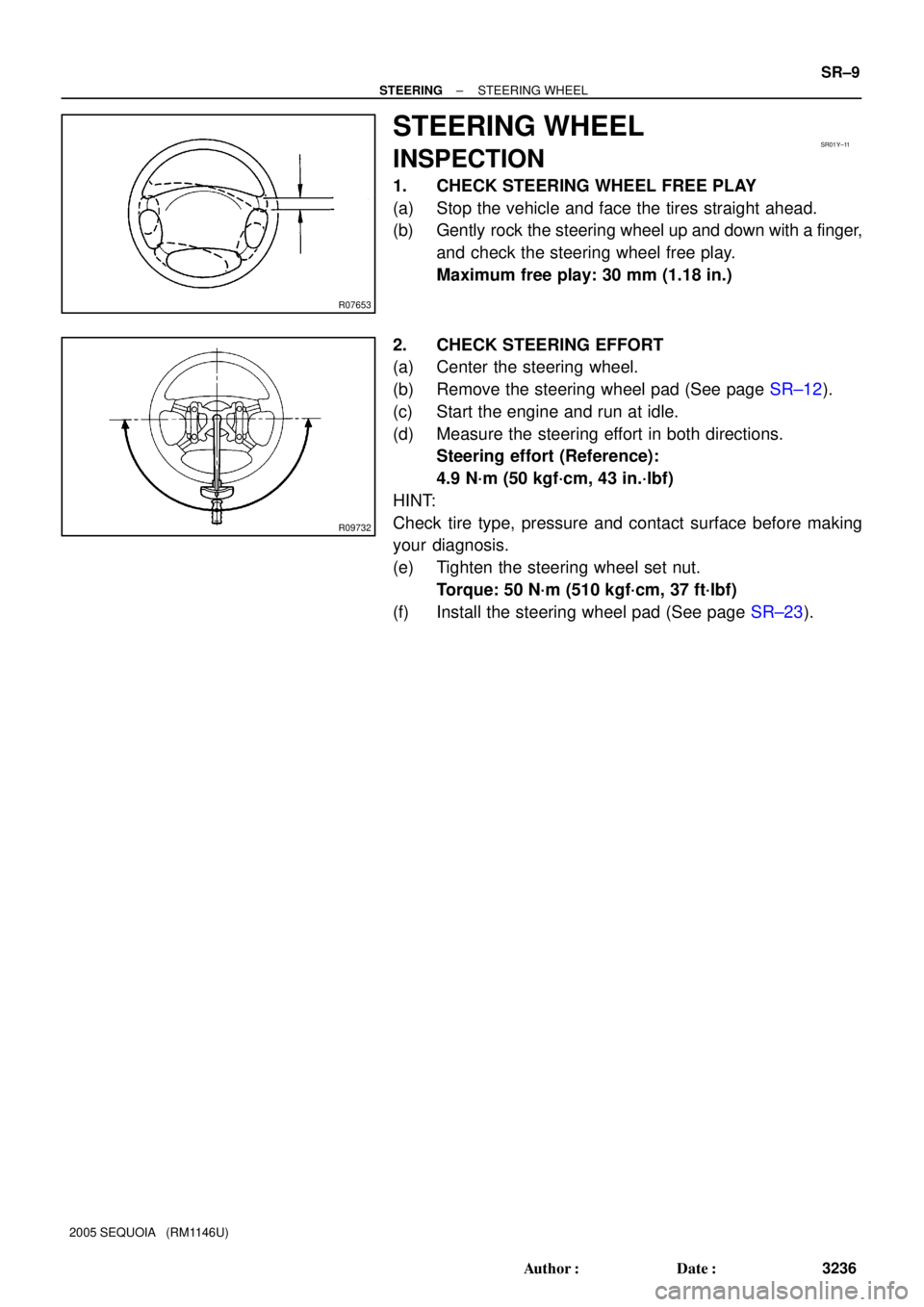
R07653
SR01Y±11
R09732
± STEERINGSTEERING WHEEL
SR±9
3236 Author�: Date�:
2005 SEQUOIA (RM1146U)
STEERING WHEEL
INSPECTION
1. CHECK STEERING WHEEL FREE PLAY
(a) Stop the vehicle and face the tires straight ahead.
(b) Gently rock the steering wheel up and down with a finger,
and check the steering wheel free play.
Maximum free play: 30 mm (1.18 in.)
2. CHECK STEERING EFFORT
(a) Center the steering wheel.
(b) Remove the steering wheel pad (See page SR±12).
(c) Start the engine and run at idle.
(d) Measure the steering effort in both directions.
Steering effort (Reference):
4.9 N´m (50 kgf´cm, 43 in.´lbf)
HINT:
Check tire type, pressure and contact surface before making
your diagnosis.
(e) Tighten the steering wheel set nut.
Torque: 50 N´m (510 kgf´cm, 37 ft´lbf)
(f) Install the steering wheel pad (See page SR±23).
Page 3417 of 4323
 Taillight does not go off when light control switch is in OFF posi-
tion.
1. TAILLIGHT Relay
2. Light Control Swit")
± BODY ELECTRICALTROUBLESHOOTING
BE±5
3409 Author�: Date�:
2005 SEQUOIA (RM1146U) Taillight does not go off when light control switch is in OFF posi-
tion.
1. TAILLIGHT Relay
2. Light Control Switch
3. Wire Harness
4. Body ECUBE±27
BE±27
±
±
Headlight does not come on when engine is running and light
control switch is in OFF position .
1. ECU±B Fuse
2. MAIN Fuse
3. HEAD Relay
4. DRL Fuse
5. DRL No. 4 Relay
6. DIMMER Relay
7. Parking Brake Switch
8. Wire Harness
9. Body ECUBE±14
BE±14
BE±27
BE±14
BE±27
BE±55
BE±55
±
±
FOG LIGHT SYSTEM
This system uses the multiplex communication system, so check diagnosis system of the multiplex commu-
nication system before you proceed with troubleshooting.
SymptomSuspect AreaSee page
Fog light does not come on with light control switch is in HEAD
position.
(Headlight is normal.)
1. FOG Fuse
2. FOG LIGHT Relay
3. Fog Light Switch
4. Wire Harness
5. Body ECUBE±14
BE±27
BE±34
±
±
Fog light does not come on with light control switch is in HEAD
position.
(Headlight does not light).1.*1 Other Parts
2. Wire Harness±
±
Only one light does not come on.1. Bulb
2. Wire Harness±
±
*1: Inspect Headlight System
TURN SIGNAL AND HAZARD WARNING SYSTEM
SymptomSuspect AreaSee page
ºHazardº and ºTurnº do not light up.
1. GAUGE Fuse
2. TURN±HAZ Fuse
3. Ignition Switch
4. Turn Signal Flasher Relay
5. Wire HarnessBE±14
BE±14
BE±24
BE±24
±
Hazard warning light does not light up.
(Turn is normal)1. Hazard Warning Switch
2. Wire Harness
3. Turn Signal Flasher RelayBE±36
±
BE±36
Turn signal does not light up.
(Hazard is normal)1. Turn Signal Switch
2. Wire Harness
3. Turn Signal Flasher RelayBE±36
±
BE±36
Turn signal does not light up in one direction.1. Bulb
2. Wire Harness±
±
Only one bulb does not light up.1. Bulb
2. Wire Harness±
±
INTERIOR LIGHT SYSTEM
This system uses the multiplex communication system, so check diagnosis system of the multiplex commu-
nication system before you proceed with troubleshooting.
SymptomSuspect AreaSee page
All the interior lights do not come on.
1. DOME Fuse
2. Illumination Circuit
3. Body ECUBE±14
DI±1759
±