Page 2839 of 4323

ON±VEHICLE INSPECTION
1. REMOVE RADIA")
CO0IZ±08
CO1242
Radiator Cap Tester
Radiator Cap
30° or More
B07240
Radiator Cap Tester
± COOLINGRADIATOR
CO±15
2831 Author�: Date�:
2005 SEQUOIA (RM1146U)
ON±VEHICLE INSPECTION
1. REMOVE RADIATOR CAP
CAUTION:
To avoid the danger of being burned, do not remove the ra-
diator cap while the engine and radiator are still hot, as fluid
and steam can be blown out under pressure.
2. INSPECT RADIATOR CAP
NOTICE:
�If the radiator cap has contaminations, always rinse
it with water.
�Before using a radiator cap tester, wet the relief valve
and pressure valve with engine coolant or water.
�When performing steps (a) and (b) below, keep the
tester at an angle of over 30° above the horizontal.
(a) Using a radiator cap tester, slowly pump the tester and
check that air is coming from the vacuum valve.
Pump speed: 1 push/(3 seconds or more)
NOTICE:
Push the pump at a constant speed.
If air is not coming from the vacuum valve, replace the radiator
cap.
(b) Pump the radiator cap tester, and measure the relief valve
opening pressure.
Pump speed: 1 push within 1 second
NOTICE:
This pump speed is for the first pump only (in order to close
the vacuum valve). After this, the pump speed can be re-
duced.
Opening pressure:
Standard74 to 103 kPa (0.75 to 1.05 kgf/cm2,10.7 to 14.9 psi)
Minimum59 kPa (0.6 kgf/cm2, 8.6 psi)
HINT:
Use the tester's maximum reading as the opening pressure.
If the opening pressure is less than minimum, replace the radia-
tor cap.
3. INSPECT COOLING SYSTEM FOR LEAKS
(a) Fill the radiator with coolant and attach a radiator cap tes-
ter.
(b) Warm up the engine.
(c) Pump it to 118 kPa (1.2 kgf/cm
2, 17.1 psi), and check that
the pressure does not drop.
If the pressure drops, check the hoses, radiator or water pump
for leaks. If no external leaks are found, check the heater core,
cylinder block and head.
4. REINSTALL RADIATOR CAP
Page 2842 of 4323
CO0UY±03
B07220
CO±18
± COOLINGRADIATOR
2834 Author�: Date�:
2005 SEQUOIA (RM1146U)
INSTALLATION
1. INSTALL NO.1 FAN SHROUD
Install the No.1 fan shroud with the 4 bolts.
Torque: 5.0 N´m (50 kgf´cm, 44 in.´lbf)
2. INSTALL RADIATOR ASSEMBLY
(a) Set the radiator bracket hooks to the radiator support
holes.
(b) Install the 4 bolts.
Torque: 12 N´m (120 N´m, 9 ft´lbf)
3. INSTALL NO.2 FAN SHROUD
Install the No.2 fan shroud with the 2 clips.
4. CONNECT A/T OIL COOLER HOSES TO RADIATOR
5. CONNECT UPPER RADIATOR HOSE TO RADIATOR
6. CONNECT LOWER RADIATOR HOSE TO RADIATOR
7. CONNECT RADIATOR RESERVOIR HOSE TO RADIA-
TOR
8. FILL WITH ENGINE COOLANT
9. START ENGINE AND CHECK FOR ENGINE COOLANT
LEAKS
10. RECHECK ENGINE COOLANT LEVEL
11. INSTALL ENGINE UNDER COVER
Page 2843 of 4323
:
TEMPERATURE RANGE ANTICIPATED BEFORE NEXT OIL CHANGE5W±30°C °F
±20
±290
±1820
±740
460
1680
27100
38
LU0GV±05
B07230
Oil Pressure Gauge
Oil Pressure Switch")
B16233
Recommended Viscosity (SAE):
TEMPERATURE RANGE ANTICIPATED BEFORE NEXT OIL CHANGE5W±30°C °F
±20
±290
±1820
±740
460
1680
27100
38
LU0GV±05
B07230
Oil Pressure Gauge
Oil Pressure Switch
P08343
Adhesive
± LUBRICATIONOIL AND FILTER
LU±1
2835 Author�: Date�:
2005 SEQUOIA (RM1146U)
OIL AND FILTER
INSPECTION
1. CHECK ENGINE OIL QUALITY
Check the oil for deterioration, entry of water, discoloring or thin-
ning.
If the quality is visibly poor, replace the oil.
Oil grade:
API grade SL Energy±Conserving or ILSAC multi-
grade engine oil.
2. CHECK ENGINE OIL LEVEL
The oil level should be between the ºLº and ºFº marks on the dip-
stick.
If low, check for leakage and add oil up to the ºFº mark.
NOTICE:
Do not fill with engine oil above the ºFº mark.
3. REMOVE ENGINE UNDER COVER
4. REMOVE OIL PRESSURE SWITCH
5. INSTALL OIL PRESSURE GAUGE
6. WARM UP ENGINE
Allow the engine to warm up to normal operating temperature.
7. CHECK OIL PRESSURE
Oil pressure:
At idle29 kPa (0.3 kgf/cm2, 4.2 psi) or more
At 3,000 rpm294 ± 588 kPa (3.0 ± 6.0 kgf/cm2, 43 ± 85 psi)
8. REMOVE OIL PRESSURE GAUGE
9. REINSTALL OIL PRESSURE SWITCH
(a) Apply adhesive to 2 or 3 threads of the oil pressure switch.
Adhesive:
Part No. 08833±00080, THREE BOND 1344, LOCTITE
242 or equivalent
(b) Reinstall the oil pressure switch.
10. START ENGINE, AND CHECK FOR ENGINE OIL
LEAKS
11. REINSTALL ENGINE UNDER COVER
Page 2845 of 4323
B07233
B07234
SST
3/4 Turn
B07235
Front
± LUBRICATIONOIL AND FILTER
LU±3
2837 Author�: Date�:
2005 SEQUOIA (RM1146U)
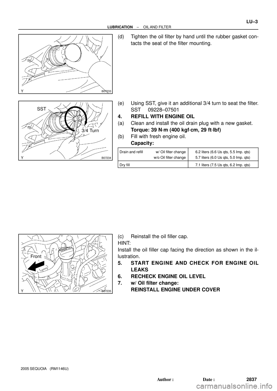
(d) Tighten the oil filter by hand until the rubber gasket con-
tacts the seat of the filter mounting.
(e) Using SST, give it an additional 3/4 turn to seat the filter.
SST 09228±07501
4. REFILL WITH ENGINE OIL
(a) Clean and install the oil drain plug with a new gasket.
Torque: 39 N´m (400 kgf´cm, 29 ft´lbf)
(b) Fill with fresh engine oil.
Capacity:
Drain and refill w/ Oil filter change
w/o Oil filter change6.2 liters (6.6 Us qts, 5.5 Imp. qts)
5.7 liters (6.0 Us qts, 5.0 Imp. qts)
Dry fill7.1 liters (7.5 Us qts, 6.2 Imp. qts)
(c) Reinstall the oil filler cap.
HINT:
Install the oil filler cap facing the direction as shown in the il-
lustration.
5. START ENGINE AND CHECK FOR ENGINE OIL
LEAKS
6. RECHECK ENGINE OIL LEVEL
7. w/ Oil filter change:
REINSTALL ENGINE UNDER COVER
Page 2854 of 4323

INSPECTION
1. INSPECT RELIEF VALVE
Coat the valve with engine oil and check that it fa")
LU08S±07
B02609
B02613
B02614
B02615
LU±12
± LUBRICATIONOIL PUMP
2846 Author�: Date�:
2005 SEQUOIA (RM1146U)
INSPECTION
1. INSPECT RELIEF VALVE
Coat the valve with engine oil and check that it falls smoothly
into the valve hole by its own weight.
If it doesn't, replace the relief valve. If necessary, replace the oil
pump assembly.
2. INSPECT DRIVE AND DRIVEN ROTORS
(a) Place the drive and driven rotors into the oil pump body.
(see page LU±14)
(b) Inspect the rotors for the body clearance.
Using a feeler gauge, measure the clearance between
the drive and driven rotor tips.
Standard tip clearance:
0.060 to 0.180 mm (0.0024 to 0.0071 in.)
Maximum tip clearance: 0.18 mm (0.0071 in.)
If the tip clearance is greater than maximum, replace the rotors
as a set.
(c) Inspect the rotors for the side clearance.
Using a feeler gauge and precision straight edge, mea-
sure the clearance between the rotors and precision
straight edge.
Side clearance:
0.030 to 0.090 mm (0.0012 to 0.0035 in.)
Maximum body clearance: 0.09 mm (0.0035 in.)
If the side clearance is greater than maximum, replace the ro-
tors as a set. If necessary, replace the oil pump assembly.
(d) Inspect the rotor for the body clearance.
Using a feeler gauge, measure the clearance between
the driven rotor and body.
Standard body clearance:
0.250 to 0.325 mm (0.0098 to 0.0128 in.)
Maximum body clearance: 0.325 mm (0.0128 in.)
If the body clearance is greater than maximum, replace the ro-
tors as a set. If necessary, replace the oil pump assembly.
(e) Remove the drive and drive rotors.
Page 2865 of 4323
LU08Z±10
B07332
New O±Ring
B07837
± LUBRICATIONOIL COOLER
LU±23
2857 Author�: Date�:
2005 SEQUOIA (RM1146U)
INSTALLATION
1. INSTALL OIL COOLER
(a) Clean the oil cooler contact surface on the cooler mount-
ing.
(b) Place a new O±ring to the oil cooler.
(c) Apply a light coat of engine oil on the threads and under
the head of the union bolt.
(d) Install the oil cooler and plate washer with the union bolt.
Torque: 68.6 N´m (700 kgf´cm, 51 ft´lbf)
(e) Connect the 2 oil cooler hoses to the oil cooler.
2. INSTALL OIL FILTER (See page LU±2)
3. FILL WITH ENGINE COOLANT
4. START ENGINE AND CHECK FOR ENGINE OIL
LEAKS
5. CHECK ENGINE OIL LEVEL
Page 2870 of 4323
IG0MF±01
± IGNITIONIGNITION SYSTEM
IG±1
2862 Author�: Date�:
2005 SEQUOIA (RM1146U)
IGNITION SYSTEM
ON±VEHICLE INSPECTION
NOTICE:
ºColdº and ºHotº in these sentences express the tempera-
ture of the coils themselves. ºColdº is from ±10°C (14°F) to
50°C (122°F) and ºHotº is from 50°C (122°F) to 100°C
(212°F).
1. INSPECT IGNITION COIL (WITH IGNITER) AND
SPARK TEST
Check that the spark occurs.
(1) Remove the ignition coils (with igniter).
(see page IG±5)
(2) Remove the spark plugs.
(3) Install the spark plugs to each ignition coil (with ig-
niter), and connect the ignition coil (with igniter) con-
nector.
(4) Disconnect the 8 injector connectors.
(5) Ground the spark plug.
(6) Check that spark occurs while engine is being
cranked.
NOTICE:
To prevent gasoline from being injected out of injectors
during this test, crank the engine for no more than 5 to 10
seconds at a time.
Page 2878 of 4323
IG08V±06
B17487
± IGNITIONCAMSHAFT POSITION SENSOR
IG±9
2870 Author�: Date�:
2005 SEQUOIA (RM1146U)
INSTALLATION
1. INSTALL CAMSHAFT POSITION SENSOR
Install the camshaft position sensor with the bolt and stud bolt
Torque: 7.5 N´m (80 kgf´cm, 66 in.´lbf)
2. INSTALL LH NO.3 TIMING BELT COVER
(See page EM±23)
3. INSTALL DRIVE BELT (See page CH±16)
4. FILL ENGINE COOLANT (See page CO±2)
5. CHECK ENGINE COOLANT FOR LEAKS
6. CHECK IGNITION TIMING (See page EM±9)