Page 1164 of 4323
F19145
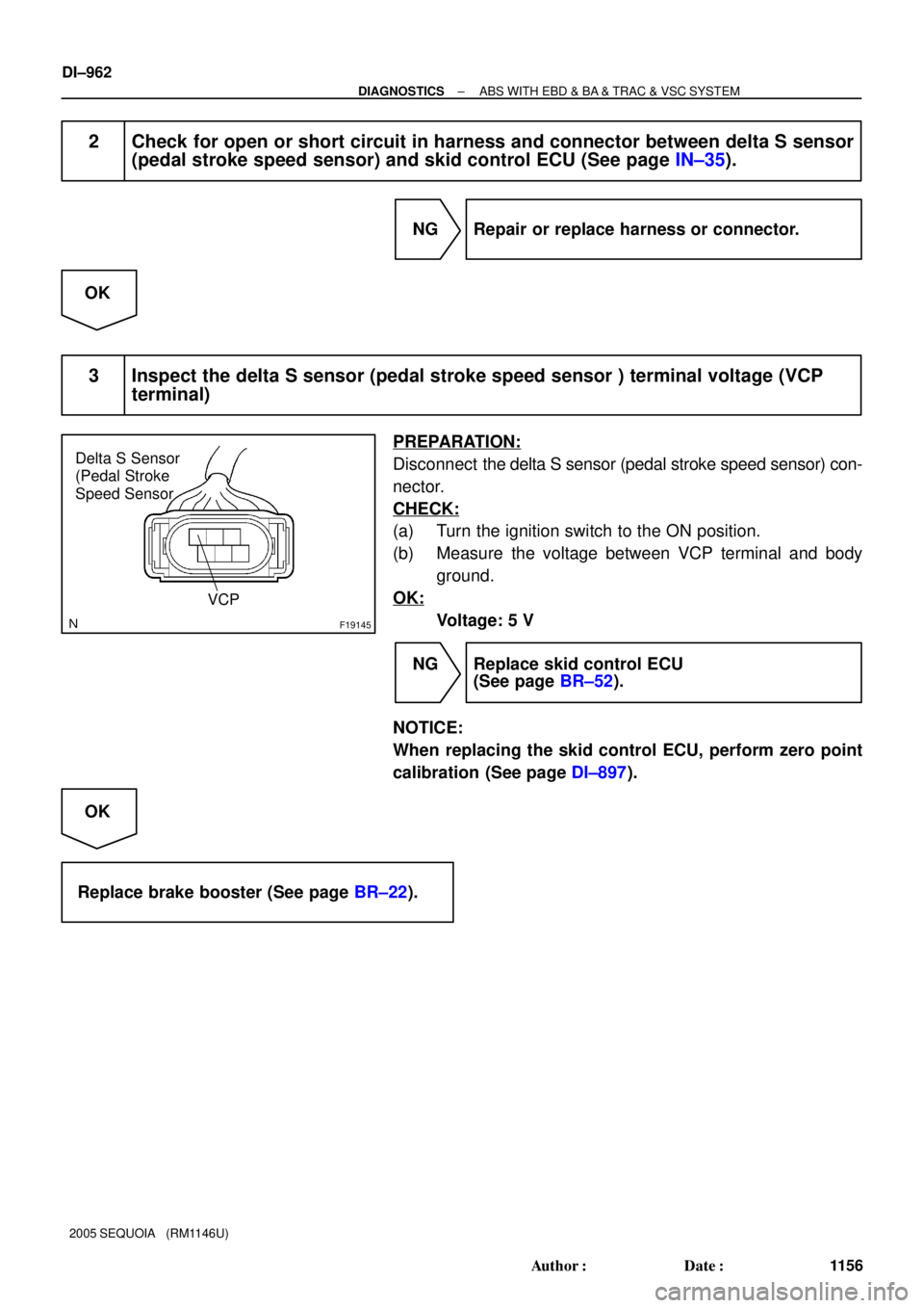
Delta S Sensor
(Pedal Stroke
Speed Sensor
VCP
DI±962
± DIAGNOSTICSABS WITH EBD & BA & TRAC & VSC SYSTEM
1156 Author�: Date�:
2005 SEQUOIA (RM1146U)
2 Check for open or short circuit in harness and connector between delta S sensor
(pedal stroke speed sensor) and skid control ECU (See page IN±35).
NG Repair or replace harness or connector.
OK
3 Inspect the delta S sensor (pedal stroke speed sensor ) terminal voltage (VCP
terminal)
PREPARATION:
Disconnect the delta S sensor (pedal stroke speed sensor) con-
nector.
CHECK:
(a) Turn the ignition switch to the ON position.
(b) Measure the voltage between VCP terminal and body
ground.
OK:
Voltage: 5 V
NG Replace skid control ECU
(See page BR±52).
NOTICE:
When replacing the skid control ECU, perform zero point
calibration (See page DI±897).
OK
Replace brake booster (See page BR±22).
Page 1167 of 4323
F16994
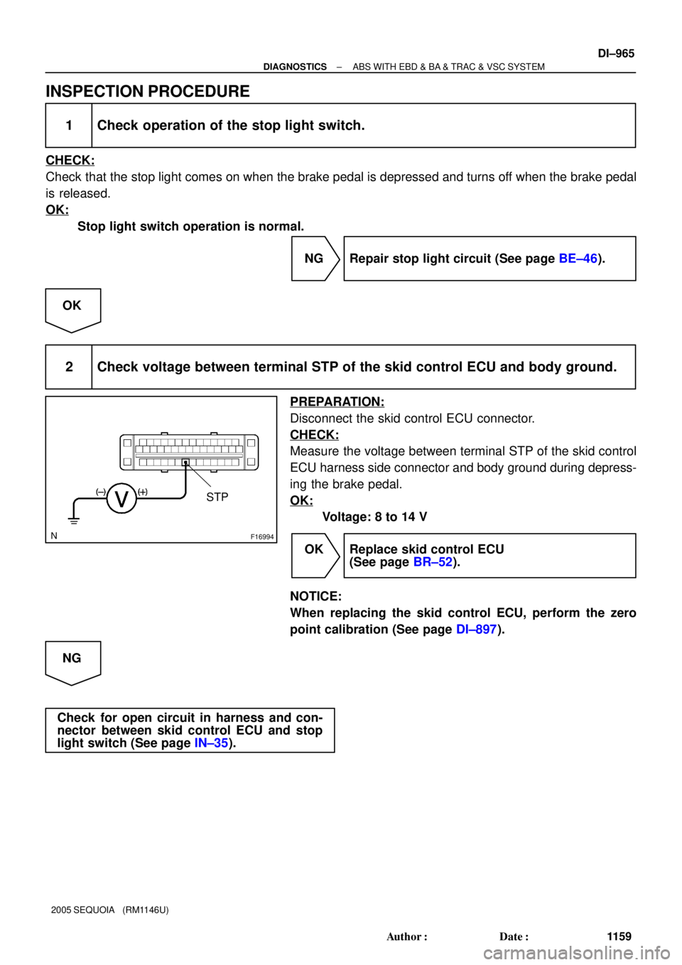
STP
± DIAGNOSTICSABS WITH EBD & BA & TRAC & VSC SYSTEM
DI±965
1159 Author�: Date�:
2005 SEQUOIA (RM1146U)
INSPECTION PROCEDURE
1 Check operation of the stop light switch.
CHECK:
Check that the stop light comes on when the brake pedal is depressed and turns off when the brake pedal
is released.
OK:
Stop light switch operation is normal.
NG Repair stop light circuit (See page BE±46).
OK
2 Check voltage between terminal STP of the skid control ECU and body ground.
PREPARATION:
Disconnect the skid control ECU connector.
CHECK:
Measure the voltage between terminal STP of the skid control
ECU harness side connector and body ground during depress-
ing the brake pedal.
OK:
Voltage: 8 to 14 V
OK Replace skid control ECU
(See page BR±52).
NOTICE:
When replacing the skid control ECU, perform the zero
point calibration (See page DI±897).
NG
Check for open circuit in harness and con-
nector between skid control ECU and stop
light switch (See page IN±35).
Page 1169 of 4323
± DIAGNOSTICSABS WITH EBD & BA & TRAC & VSC SYSTEM
DI±967
1161 Author�: Date�:
2005 SEQUOIA (RM1146U)
INSPECTION PROCEDURE
1 Check pump motor operation.
PREPARATION:
(a) Select the item ºABS MOTOR RELAYº in the ACTIVE TEST and operate the ABS motor relay on the
hand±held tester.
(b) Check the operation sound of the ABS pump motor when operating it with the hand±held tester.
ItemVehicle Condition / Test DetailsDiagnostic Note
ABS MOT RELAYTurns ABS motor relay ON / OFFOperation of motor (click-
ing sound) can be heard
CHECK:
The operation sound of the pump motor should be heard.
OK:
Operation sound can be heard.
NG Go to step 2.
OK
Check and replace ABS & VSC actuator with
skid control ECU (See page BR±52).
NOTICE:
When replacing the skid control ECU, perform the zero point calibration (See page DI±897).
Page 1170 of 4323
F16991
GND
DI±968
± DIAGNOSTICSABS WITH EBD & BA & TRAC & VSC SYSTEM
1162 Author�: Date�:
2005 SEQUOIA (RM1146U)
2 Check continuity between terminal GND of the skid control ECU connector and
body ground.
PREPARATION:
Disconnect the skid control ECU connector.
CHECK:
Measure the resistance between terminal GND of the skid con-
trol ECU harness side connector and body ground.
OK:
Resistance: 1 W or less
NG Repair or replace harness or connector.
OK
Check and replace ABS & VSC actuator with
skid control ECU (See page BR±52).
NOTICE:
When replacing the skid control ECU, perform the zero point calibration (See page DI±897).
Page 1172 of 4323
F13988
34
DI±970
± DIAGNOSTICSABS WITH EBD & BA & TRAC & VSC SYSTEM
1164 Author�: Date�:
2005 SEQUOIA (RM1146U)
INSPECTION PROCEDURE
1 Check active brake booster solenoid.
PREPARATION:
Disconnect the connector from the brake booster.
CHECK:
Check resistance between terminals 3 and 4 of the brake boost-
er.
OK:
Resistance: 1.1 to 1.7 W
NG Replace brake booster.
OK
2 Check for open and short circuit in harness and connector between skid control
ECU and brake booster (See page IN±35).
NG Repair or replace harness or connector.
OK
Replace skid control ECU
(See page BR±52).
NOTICE:
When replacing the skid control ECU, perform the zero point calibration (See page DI±897).
Page 1176 of 4323
F17285
1
2 34
1
4
3
2
DI±974
± DIAGNOSTICSABS WITH EBD & BA & TRAC & VSC SYSTEM
1168 Author�: Date�:
2005 SEQUOIA (RM1146U)
2 Check brake inhibit relay.
CHECK:
Check continuity between the following terminals of the brake
inhibit relay.
OK:
Terminals 1 and 2Continuity
(Reference value 62 W)
Terminals 3 and 4Continuity
CHECK:
(a) Apply battery positive voltage between terminals 1 and 2.
(b) Check continuity between terminals.
Terminals 3 and 4Open
NG Replace brake inhibit relay.
OK
3 Check for open and short circuit in harness and connector between brake inhibit
relay and skid control ECU (See page IN±35).
NG Repair or replace harness or connector.
OK
If the same code is still indicated after the DTC is deleted, check the condition of each connection.
If the connections are normal, the skid control ECU may be defective.
NOTICE:
When replacing the skid control ECU, perform the zero point calibration (See page DI±897).
Page 1177 of 4323
± DIAGNOSTICSABS WITH EBD & BA & TRAC & VSC SYSTEM
DI±975
1169 Author�: Date�:
2005 SEQUOIA (RM1146U)
DTC C1337 / 37 Some Tire Are Different in Size From
the Other Tires
CIRCUIT DESCRIPTION
Skid control ECU measure the speed of each wheel by receiving signals from speed sensor. These signals
are used for recognizing all 4 wheels are operating properly. Therefore, all wheel signals must be equal.
DTC No.DTC Detecting ConditionTrouble Area
C1337 / 371 or 2 tires of different size are used for driving.Tire size
INSPECTION PROCEDURE
1 Check tire size.
CHECK:
Check tire size and condition of all 4 wheels.
NG Replace tires so that all 4 tires are the same in
size.
OK
2 Check speed sensor (See page DI±925).
NG Replace speed sensor.
OK
3 Check speed sensor rotor (See page DI±925).
NG Replace speed sensor rotor.
OK
DI93T±03
Page 1178 of 4323
DI±976
± DIAGNOSTICSABS WITH EBD & BA & TRAC & VSC SYSTEM
1170 Author�: Date�:
2005 SEQUOIA (RM1146U)
4 Check harness and connector between speed sensor and skid control ECU
(See page IN±35).
NG Repair or replace harness or connector.
OK
Replace skid control ECU
(See page BR±52).
NOTICE:
When replacing the skid control ECU, perform the zero point calibration (See page DI±897).