Page 1152 of 4323

6 Replace the skid control ECU and check if trouble occurs again.
PREPARATION:
(a) Clear the D")
DI±950
± DIAGNOSTICSABS WITH EBD & BA & TRAC & VSC SYSTEM
1144 Author�: Date�:
2005 SEQUOIA (RM1146U)
6 Replace the skid control ECU and check if trouble occurs again.
PREPARATION:
(a) Clear the DTC.
(b) Turn the ignition switch OFF.
CHECK:
Check if the same DTC still remains in the memory.
RESULT:
DTC is outputA
DTC is not outputB
B END.
A
Replace steering angle sensor.
NOTICE:
�When replacing the skid control ECU, perform the zero point calibration (See page DI±897).
�If the steering angle sensor has been replaced, drive the vehicle straight ahead at a speed of
6.5 mph (10.5 km/h) or more to calibrate the steering angle sensor.
7 Check DTC once more (See page DI±911).
PREPARATION:
(a) Clear the DTC.
(b) Turn the ignition switch OFF.
CHECK:
Check if the same DTC still remains in the memory.
RESULT:
DTC is outputA
DTC is not outputB
B END.
A
Replace skid control ECU with actuator
(See page BR±52).
NOTICE:
When replacing the skid control ECU, perform the zero point calibration (See page DI±897).
Page 1154 of 4323

F19199
DI±952
± DIAGNOSTICSABS WITH EBD & BA & TRAC & VSC SYSTEM
1146 Author�: Date�:
2005 SEQUOIA (RM1146U)
INSPECTION PROCEDURE
1 Check the yaw rat")
F19784
Torque: 5 N´m (10 kgf´cm, 3.7ft´lbf)
F19199
DI±952
± DIAGNOSTICSABS WITH EBD & BA & TRAC & VSC SYSTEM
1146 Author�: Date�:
2005 SEQUOIA (RM1146U)
INSPECTION PROCEDURE
1 Check the yaw rate (deceleration) sensor installation.
CHECK:
Check the yaw rate (deceleration) sensor installation.
OK:
The sensor should be tightened to the specified
torque.
The sensor should not be tilted.
NG Install yaw
rate (deceleration) sensor correctly.
OK
2 Check output value of the yaw rate sensor.
PREPARATION:
(a) Remove the 2 bolts and the yaw rate (deceleration) sen-
sor assembly with the connector still connected.
(b) Connect the hand±held tester to the DLC3.
(c) Turn the ignition switch to the ON position and push the
hand±held tester main switch ON.
(d) Select DATA LIST mode on the hand±held tester.
CHECK:
Check that the decelerate value of the deceleration sensor dis-
played on the hand±held tester changes: Place the decelera-
tion sensor vertically to the ground and turn the sensor to the
frontward and rearward.
ItemMeasurement Item /
Range (Display)Normal ConditionDiagnostic Note
DECELERAT SENS
Deceleration sensor 1
reading / min.: ±1.869 G,
max.: 1.869 GApproximately 0 ± 0.13 G
while stationaryReading changes when ve-
hicle is bounced
DECELERAT SENS2
Deceleration sensor 2
reading / min.: ±1.869 G,
max.: 1.869 GApproximately 0 ± 0.13 G
while stationaryReading changes when ve-
hicle is bounced
OK:
Decelerate value changes.
NG Replace yaw rate (deceleration) sensor.
NOTICE:
When replacing the yaw rate (deceleration) sensor, per-
form the zero point calibration (See page DI±897).
OK
Page 1155 of 4323
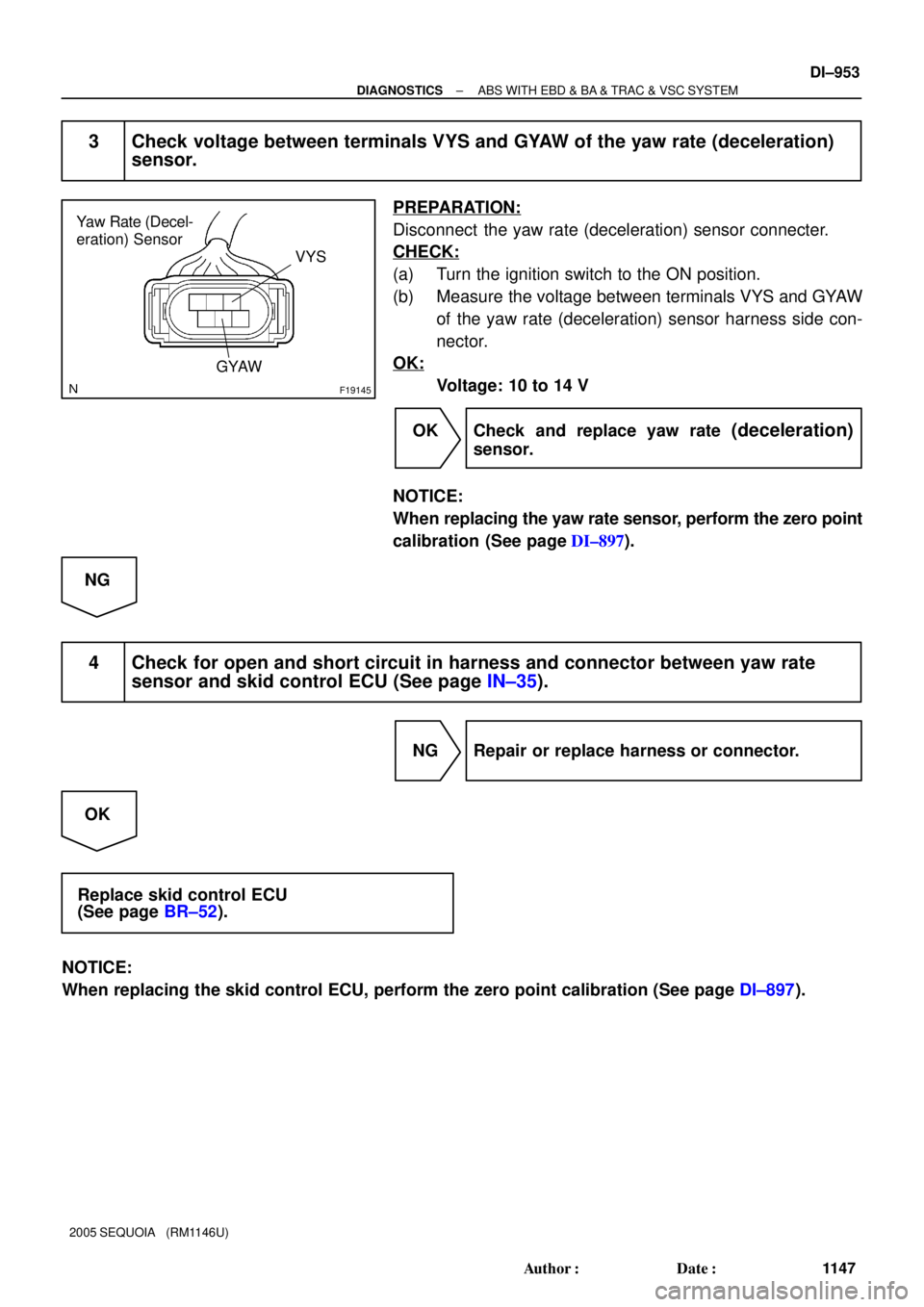
F19145
Yaw Rate (Decel-
eration) Sensor
VYS
GYAW
± DIAGNOSTICSABS WITH EBD & BA & TRAC & VSC SYSTEM
DI±953
1147 Author�: Date�:
2005 SEQUOIA (RM1146U)
3 Check voltage between terminals VYS and GYAW of the yaw rate (deceleration)
sensor.
PREPARATION:
Disconnect the yaw rate (deceleration) sensor connecter.
CHECK:
(a) Turn the ignition switch to the ON position.
(b) Measure the voltage between terminals VYS and GYAW
of the yaw rate (deceleration) sensor harness side con-
nector.
OK:
Voltage: 10 to 14 V
OK Check and replace yaw rate
(deceleration)
sensor.
NOTICE:
When replacing the yaw rate sensor, perform the zero point
calibration (See page DI±897).
NG
4 Check for open and short circuit in harness and connector between yaw rate
sensor and skid control ECU (See page IN±35).
NG Repair or replace harness or connector.
OK
Replace skid control ECU
(See page BR±52).
NOTICE:
When replacing the skid control ECU, perform the zero point calibration (See page DI±897).
Page 1157 of 4323

F16996
± DIAGNOSTICSABS WITH EBD & BA & TRAC & VSC SYSTEM
DI±955
1149 Author�: Date�:
2005 SEQUOIA (RM1146U)
INSPECTION PROCEDURE
1 Check the yaw rat")
F19784
Torque: 5 N´m (10 kgf´cm, 3.7ft´lbf)
F16996
± DIAGNOSTICSABS WITH EBD & BA & TRAC & VSC SYSTEM
DI±955
1149 Author�: Date�:
2005 SEQUOIA (RM1146U)
INSPECTION PROCEDURE
1 Check the yaw rate sensor installation.
CHECK:
Check the yaw rate sensor installation.
OK:
The sensor should be tightened to the specified
torque.
The sensor should not be tilted.
NG Install yaw
rate sensor correctly.
OK
2 Check output value of the yaw rate sensor.
PREPARATION:
(a) Remove the 2 bolts and the yaw rate sensor assembly
with the connector still connected.
(b) Connect the hand±held tester to the DLC3.
(c) Turn the ignition switch to the ON position and push the
hand±held tester main switch ON.
(d) Select the DATA LIST mode on the hand±held tester.
CHECK:
Check that the yaw rate value of the yaw rate sensor displayed
on the hand±held tester changes: Place the yaw rate sensor
vertically to the ground and turn the sensor to the right and left.
ItemMeasurement Item /
Range (Display)Normal ConditionDiagnostic Note
YAW RATE
Yaw rate sensor/
Min.: ±128 deg/s, Max.:
127 deg/sMin.: ±128 deg/s
Max.: 128 deg/s±
OK:
Yaw rate value changes.
NG Replace yaw rate sensor.
NOTICE:
When replacing the yaw rate sensor, perform the zero point
calibration (See page DI±897).
OK
Page 1158 of 4323
F19145
Yaw Rate Sensor
VYS
GYAW
DI±956
± DIAGNOSTICSABS WITH EBD & BA & TRAC & VSC SYSTEM
1150 Author�: Date�:
2005 SEQUOIA (RM1146U)
3 Check voltage between terminal VYS and GYAW of the yaw rate sensor.
PREPARATION:
Disconnect the yaw rate sensor connecter.
CHECK:
(a) Turn the ignition switch to the ON position.
(b) Measure the voltage between terminal VYS and GYAW
of the yaw rate sensor harness side connector.
OK:
Voltage: 10 to 14 V
OK Check and replace yaw rate sensor.
NOTICE:
When replacing the yaw rate sensor, perform the zero point
calibration (See page DI±897).
NG
4 Check for open and short circuit in harness and connector between yaw rate
sensor and skid control ECU (See page IN±35).
NG Repair or replace harness or connector.
OK
Replace skid control ECU
(See page BR±52).
NOTICE:
When replacing the skid control ECU, perform the zero point calibration (See page DI±897).
Page 1160 of 4323
DI±958
± DIAGNOSTICSABS WITH EBD & BA & TRAC & VSC SYSTEM
1152 Author�: Date�:
2005 SEQUOIA (RM1146U)
INSPECTION PROCEDURE
1 Check ABS fuse.
PREPARATION:
Remove the ABS fuse from the fusible link block.
CHECK:
Check continuity of the ABS fuse.
OK:
Continuity
NG Check for short circuit in all the harnesses and
components connected to ABS fuse (See at-
tached wiring diagram).
OK
2 Check battery positive voltage.
OK:
Voltage: 10 to 14 V
NG Check and repair the charging system
(See page CH±1).
OK
Page 1161 of 4323
F16988
GND+BM
+BS
F16991
GND
± DIAGNOSTICSABS WITH EBD & BA & TRAC & VSC SYSTEM
DI±959
1153 Author�: Date�:
2005 SEQUOIA (RM1146U)
3 Check voltage of the +BM/+BS power source.
PREPARATION:
Disconnect the skid control ECU connector.
CHECK:
Measure the voltage between terminal +BM/+BS and GND of
the skid control ECU harness side connector.
OK:
Voltage: 10 to 14 V
OK Replace skid control ECU
(See page BR±52).
NOTICE:
When replacing the skid control ECU, perform the zero
point calibration (See page DI±897).
NG
4 Check continuity between terminal GND of the skid control ECU connector and
body ground (See page IN±35).
PREPARATION:
Disconnect the skid control ECU connector.
CHECK:
Measure the resistance between terminal GND of the skid con-
trol ECU harness side connector and body ground.
OK:
Resistance: 1 W or less
NG Repair or replace harness or connector.
OK
Check for open circuit in harness and connector between skid control ECU and battery
(See page IN±35).
Page 1163 of 4323
: Brake Pedal
Depressed
(2): Brake Pedal
Released Voltage
Time 4.5 V
1.9 V
0.5 V(2)
(1)
± DIAGNOSTICSABS WITH EBD & BA & TRAC & VSC SYSTEM
DI±961
1155 Author�: Date�:
2005 SEQUOIA (RM11")
F19800
(1): Brake Pedal
Depressed
(2): Brake Pedal
Released Voltage
Time 4.5 V
1.9 V
0.5 V(2)
(1)
± DIAGNOSTICSABS WITH EBD & BA & TRAC & VSC SYSTEM
DI±961
1155 Author�: Date�:
2005 SEQUOIA (RM1146U)
INSPECTION PROCEDURE
HINT:
Start the inspection from step 1 in the case of using the hand±held tester and start from step 2 in the case
of not using the hand±held tester.
1 Check output value of the delta S sensor (pedal stroke speed sensor) using the
hand±held tester.
PREPARATION:
(a) Connect the hand±held tester to the DLC3.
(b) Turn the ignition switch to the ON position.
(c) Run the engine until the engine speed reaches 3,000 rpm, and return it back to idle.
HINT:
Rev up the engine to ensure sufficient vacuum.
(d) Select DATA LIST mode on the hand±held .
ItemMeasurement Item /
Range (Display)Normal ConditionDiagnostic Note
PEDAL STROKEPedal stroke sensor/
min.: 0 V, max.: 5.1 V
Approximately 2.0 V with-
out the brake pedal de-
pressed.
±
HINT:
�The result appears on the tester after some delay because a time lag occurs in measurement with a
hand±held tester.
�If a signal from the delta S sensor is sent between sampling, the result does not appear on the tester.
So be sure to perform the measurement 2 or 3 times.
CHECK:
Check that the brake pedal acceleration value of the delta S sensor displayed on the hand±held tester
changes, alternatively increasing the brake pedal stroke.
OK:
The value changes as shown in the illustration on the
left. (The value will return to approximately 2.0 V after
the brake pedal is released.)
HINT:
The maximum voltage depends on pedal stroke speed but
should not exceed 4.5 V or fall below 0.2 V.
OK Replace skid control ECU
(See page BR±52).
NOTICE:
When replacing the skid control ECU, perform zero point
calibration (See page DI±897).
NG