Page 1124 of 4323

*1: As long as the following operations are not performed, the ABS warning light will not go")
DI±922
± DIAGNOSTICSABS WITH EBD & BA & TRAC & VSC SYSTEM
111 6 Author�: Date�:
2005 SEQUOIA (RM1146U)
*1: As long as the following operations are not performed, the ABS warning light will not go OFF only by re-
pairing the trouble area.
(1) Drive the vehicle at 12 mph (20 km/h) for 30 seconds or more and check that the ABS warning light goes
off.
(2) Clear the DTC (See page DI±911).
HINT:
There is a possibility that the hand±held tester cannot be used when the ABS warning light is always ON.
DTC chart of VSC system:
DTC No.
(See Page)Detection ItemTrouble Area
C1201/51
(DI±936)Engine control system malfunction�Engine control system
C1202/52
(DI±937)Brake fluid level warning switch circuit
�Brake fluid level
�Brake fluid level warning switch
�Brake fluid level warning switch circuit
�Skid control ECU
�CAN1 communication system
�Translate ECU
C1203/53 *1
(DI±942)Malfunction in CAN1 communication
�Skid control ECU
�CAN1 communication system
�ECM
�Translate ECU
C1207/37
(DI±522)Reverse gear signal failureECT
C1223/43
(DI±945)Malfunction in ABS control systemABS control system
C1231/31
(DI±946)Malfunction in steering angle sensor
�Steering angle sensor
�Steering angle sensor communication circuit
�Skid control ECU
�Translate ECU
�CAN communication system
C1232/32
(DI±951)Malfunction in deceleration sensor�Yaw rate (deceleration) sensor
�Yaw rate (deceleration) sensor circuit
C1234/34
(DI±954)Malfunction in yaw rate sensor�Yaw rate (deceleration) sensor
�Yaw rate (deceleration) sensor circuit
C1310/11
(DI±969)Open or short circuit in active brake booster solenoid circuit�Brake booster
�Active brake booster solenoid circuit
C1311/12
(DI±971)Open or short circuit in brake inhibit relay circuit�Brake inhibit relay
�Brake inhibit relay circuit
1335/35
(DI±946)Malfunction in steering angle sensor communication circuit
�Steering angle sensor
�Steering angle sensor communication circuit
�Skid control ECU
�Translate ECU
�CAN1 communication system
C1340/47*2
(DI±977)Center diff. lock circuit malfunction
�Center diff. lock position switch
�Center diff. lock position switch circuit
�Center diff. lock indicator light circuit
�Translate ECU
C1360/61
(DI±983)Malfunction in master cylinder pressure sensor�Master cylinder pressure sensor
�Master cylinder pressure sensor circuit
Page 1125 of 4323
C1361/62
(DI±986)
Abnormal battery voltage of VSC sensor
�Battery
�Charging system
�Power sou")
± DIAGNOSTICSABS WITH EBD & BA & TRAC & VSC SYSTEM
DI±923
111 7 Author�: Date�:
2005 SEQUOIA (RM1146U)C1361/62
(DI±986)
Abnormal battery voltage of VSC sensor
�Battery
�Charging system
�Power source circuit
�Yaw rate (deceleration) sensor
�Skid control ECU
�Master cylinder pressure sensor
C1362/36
(DI±990)Malfunction in sensor offset value (VSC sensor system)Skid control ECU
(Perform zero point calibration)
C1363/63
(DI±991)Malfunction in booster pedal force switch�Booster pedal force switch (Active brake booster)
�Booster pedal force switch (Active brake booster) circuit
U0100/65
(DI±1075)Malfunction in vehicle CAN communication system�Vehicle CAN communication system
HINT:
There is a possibility that the hand±held tester cannot be used when the VSC TRAC warning light is always
ON.
*
1: Check DTC chart C1203/53 first, then troubleshoot according to the DTC chart of translate ECU if neces-
sary.
*
2:
4WD
DTC chart of translate ECU (When DTC ºC1201/51, C1202/52, C1203/53 or U0100/65º of VSC system
is output):
DTC No.
(See Page)Detection ItemTrouble Area
Normal code*
(DI±1013)Malfunction in ECM control system or suspension control ECU
�ECM circuit
�ECM
�Brake fluid level
�Brake fluid level warning switch circuit
�Steering angle sensor
�Translate ECU
�Skid control ECU
�Vehicle CAN
�VSC+, VSC± circuit (CAN1 communication system)
51
(DI±995)Malfunction in ECM control system�ECM
53
(DI±998)Malfunction in CAN1 communication
�VSC+, VSC± circuit (CAN1 communication system)
�Skid control ECU
�Translate ECU
58
(DI±1002)Malfunction of brake fluid level switch
�Brake fluid level warning switch circuit
�Brake fluid level warning switch
�Brake fluid reservoir level
�Translate ECU
65
(DI±1005)Malfunction 1 of vehicle CAN
�ENG+, ENG± circuit (CAN communication system)
�ECM
�Translate ECU
�Suspension control ECU
94
(DI±1009)Malfunction 2 of vehicle CAN
�ENG+, ENG± circuit (CAN communication system)
�ECM
�Translate ECU
�Suspension control ECU
Non±code
(DI±1015)Malfunction in translate ECU
�Brake warning light circuit
�Tc terminal circuit
�Translate ECU
*: Translate ECU is normal.
Page 1130 of 4323

2 Check speed sensor.
Front:
PREPARATION:
(a) Make sure that there is no l")
R14205
21
R14205
21
DI±928
± DIAGNOSTICSABS WITH EBD & BA & TRAC & VSC SYSTEM
1122 Author�: Date�:
2005 SEQUOIA (RM1146U)
2 Check speed sensor.
Front:
PREPARATION:
(a) Make sure that there is no looseness at the connector
lock part and connecting part of the connector.
(b) Disconnect the speed sensor connector.
CHECK:
Measure the resistance between terminals 1 and 2 of the speed
sensor connector.
OK:
Resistance: 0.92 to 1.22 kW
CHECK:
Measure the resistance between terminals 1 and 2 of the speed
sensor connector and body ground.
OK:
Resistance: 1 MW or higher
Rear:
PREPARATION:
(a) Make sure that there is no looseness at the connector
lock part and connecting part of the connector.
(b) Disconnect the speed sensor connector.
CHECK:
Measure the resistance between terminals 1 and 2 of the speed
sensor connector.
OK:
Resistance: 1.8 to 2.2 kW
CHECK:
Measure the resistance between terminals 1 and 2 of the speed
sensor connector and body ground.
OK:
Resistance: 1 MW or higher
NG Replace speed sensor
(See page BR±56 or BR±59).
NOTICE:
Check the speed sensor signal after replacement (See
page DI±899).
OK
Page 1131 of 4323
BR3795OKNG
± DIAGNOSTICSABS WITH EBD & BA & TRAC & VSC SYSTEM
DI±929
1123 Author�: Date�:
2005 SEQUOIA (RM1146U)
3 Check for open and short circuit in harness and connector between each speed
sensor and skid control ECU (See page IN±35).
NG Repair or replace harness or connector.
OK
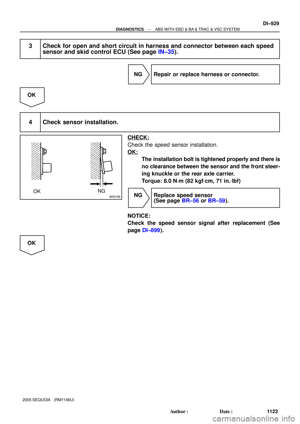
4 Check sensor installation.
CHECK:
Check the speed sensor installation.
OK:
The installation bolt is tightened properly and there is
no clearance between the sensor and the front steer-
ing knuckle or the rear axle carrier.
Torque: 8.0 N´m (82 kgf´cm, 71 in.´lbf)
NG Replace speed sensor
(See page BR±56 or BR±59).
NOTICE:
Check the speed sensor signal after replacement (See
page DI±899).
OK
Page 1132 of 4323

5 Check speed sensor an")
W04200
Normal Signal Waveform
1 V / Division2 m/s / DivisionGND
R07880
DI±930
± DIAGNOSTICSABS WITH EBD & BA & TRAC & VSC SYSTEM
1124 Author�: Date�:
2005 SEQUOIA (RM1146U)
5 Check speed sensor and sensor rotor serrations.
INSPECTION USING OSCILLOSCOPE
PREPARATION:
Connect the oscilloscope to the terminal FR+ ± FR±, FL+ ± FL±,
RR+ ± RR± and RL+ ± RL± of the skid control ECU.
CHECK:
Drive the vehicle at about 12 mph (20 km/h), and check the sig-
nal waveform.
OK:
A waveform as shown in the figure should be output.
HINT:
�As the vehicle speed (wheel revolution speed) increases,
a cycle of the waveform becomes shorter and the fluctua-
tion in the output voltage becomes greater.
�When noise is identified in the waveform on the oscillo-
scope, error signals are generated due to the speed sen-
sor rotor's scratches, looseness or foreign matter depos-
ited on it.
OK Replace skid control ECU
(See page BR±52).
NOTICE:
When replacing the skid control ECU, perform the zero
point calibration (See page DI±897).
NG
6 Check sensor rotor and sensor tip.
Front:
PREPARATION:
Remove the disc (See page SA±22).
CHECK:
Check the sensor rotor serrations.
OK:
No scratches, missing teeth or foreign objects.
PREPARATION:
Remove the front speed sensor (See page BR±56).
CHECK:
Check the sensor tip.
OK:
No scratches or foreign objects on the sensor tip.
HINT:
Remove any foreign matter if identified.
Check the output waveform again after reassembly.
Page 1133 of 4323
W02871
± DIAGNOSTICSABS WITH EBD & BA & TRAC & VSC SYSTEM
DI±931
1125 Author�: Date�:
2005 SEQUOIA (RM1146U)
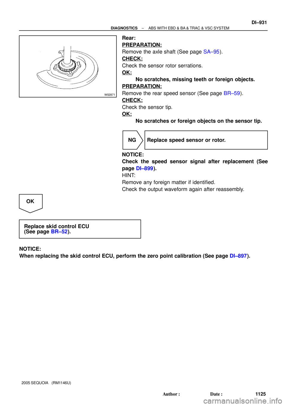
Rear:
PREPARATION:
Remove the axle shaft (See page SA±95).
CHECK:
Check the sensor rotor serrations.
OK:
No scratches, missing teeth or foreign objects.
PREPARATION:
Remove the rear speed sensor (See page BR±59).
CHECK:
Check the sensor tip.
OK:
No scratches or foreign objects on the sensor tip.
NG Replace speed sensor or rotor.
NOTICE:
Check the speed sensor signal after replacement (See
page DI±899).
HINT:
Remove any foreign matter if identified.
Check the output waveform again after reassembly.
OK
Replace skid control ECU
(See page BR±52).
NOTICE:
When replacing the skid control ECU, perform the zero point calibration (See page DI±897).
Page 1135 of 4323
± DIAGNOSTICSABS WITH EBD & BA & TRAC & VSC SYSTEM
DI±933
1127 Author�: Date�:
2005 SEQUOIA (RM1146U)
INSPECTION PROCEDURE
1 Check DTC once more (See page DI±911).
PREPARATION:
(a) Clear the DTC.
(b) Turn the ignition switch OFF.
CHECK:
Turn the ignition switch to the ON position, and check if the same DTC still remains in the memory.
RESULT:
DTC is outputA
DTC is not outputB
B No problem.
A
Replace skid control ECU with actuator
(See page BR±51).
NOTICE:
When replacing the skid control ECU, perform the zero point calibration (See page DI±897).
Page 1137 of 4323
F16988
GND
+BM
+BS
± DIAGNOSTICSABS WITH EBD & BA & TRAC & VSC SYSTEM
DI±935
1129 Author�: Date�:
2005 SEQUOIA (RM1146U)
INSPECTION PROCEDURE
1 Check voltage between terminals +BS, +BM and GND of the skid control ECU
connector.
PREPARATION:
Disconnect the skid control ECU connector.
CHECK:
Measure the voltage between terminals +BS, +BM and GND of
the skid control ECU harness side connector.
OK:
Voltage: 10 to 14 V
NG Check and replace ABS fuses.
Check and repair harness or connector.
OK
If the same code is still indicated after the DTC is deleted, check the condition of each connection.
If the connections are normal, the skid control ECU may be defective.
NOTICE:
When replacing the skid control ECU, perform the zero point calibration (See page DI±897).