Page 1070 of 4323
F19138
Tire Pressure Monitor ECU:
T17
CALSW
GND2
DI±868
± DIAGNOSTICSTIRE PRESSURE WARNING SYSTEM
1062 Author�: Date�:
2005 SEQUOIA (RM1146U)
16 Inspect tire pressure monitor ECU.
PREPARATION:
Connect the tire pressure monitor ECU T17 connector.
CHECK:
Measure the voltage according to the value(s) in the table be-
low.
OK:
Tester connectionConditionSpecified condition
T17±10 (CALSW) ±
T17±16 (GND2)IG Switch ON to OFF8 to 16 V
NG Repair or replace harness or connector.
OK
17 Check DTC (See page DI±820).
PREPARATION:
Clear the DTCs.
CHECK:
Check for a DTC.
OK:
DTC is not output.
OK End
NG
Page 1071 of 4323
± DIAGNOSTICSTIRE PRESSURE WARNING SYSTEM
DI±869
1063 Author�: Date�:
2005 SEQUOIA (RM1146U)
18 Replace tire pressure monitor ECU and check DTC.
PREPARATION:
(a) Replace the tire pressure monitor ECU (see page SA±20).
(b) Clear the DTCs.
CHECK:
Check for a DTC.
OK:
DTC is not output.
NG Replace tire pressure monitor valve sub±assy
(See page SA±16).
OK
End
Page 1073 of 4323

INSPECTION PROCEDURE
NOTIC")
F19136
Tire Pressure Monitor ECU:
T17
SPD
F19755
C5±20Combination
Meter
C5
± DIAGNOSTICSTIRE PRESSURE WARNING SYSTEM
DI±871
1065 Author�: Date�:
2005 SEQUOIA (RM1146U)
INSPECTION PROCEDURE
NOTICE:
It is necessary to register an ID code after replacing the tire pressure monitor valve sub±assy and/or
the tire pressure monitor ECU (see page DI±805).
HINT:
When not using the hand±held tester, go to step 2.
1 Read value on hand±held tester.
PREPARATION:
(a) Connect the hand±held tester to the DLC3.
(b) Turn the ignition switch to the ON position, and push the hand±held tester main switch ON.
(c) Select the item below in the DATA LIST, and read its value displayed on the hand±held tester.
TIRE PRESSURE:
ItemNormal Condition
VEHICLE SPEEDActual vehicle speed
CHECK:
Check that the values indicated on the tester and the combination meter are the same.
OK:
Indicates actual speed.
OK Replace tire pressure monitor ECU
(See page SA±20).
NG
2 Check harness and connector (Tire pressure monitor ECU ± Combination meter
assy).
PREPARATION:
Disconnect the combination meter assy C5 connector and tire
pressure monitor ECU T17 connector.
CHECK:
Measure the resistance according to the value(s) in the table
below.
OK:
Tester ConnectionSpecified Condition
T17±3 (SPD) ± C5±20Below 1 W
T17±3 (SPD) ± Body ground10 kW or higher
Page 1074 of 4323
F19138
Tire Pressure Monitor ECU:
SPD
GND
T17
9 to 14 V
0
Turn the wheel
DI±872
± DIAGNOSTICSTIRE PRESSURE WARNING SYSTEM
1066 Author�: Date�:
2005 SEQUOIA (RM1146U)
NG Repair or replace harness or connector.
OK
3 Inspect tire pressure monitor ECU.
PREPARATION:
Remove the tire pressure monitor ECU with connectors still
connected.
CHECK:
Check voltage.
(1) Shift the shift lever to neutral.
(2) Jack up one of the front wheels.
(3) Turn the ignition switch to the ON position.
(4) Measure the voltage between terminals SPD and
GND of the tire pressure monitor ECU when the
front wheel is turned slowly.
OK:
Voltage is generated intermittently.
HINT:
As the vehicle speed (wheel revolution speed) increases, a
cycle of the waveform narrows.
NG Check combination meter assy (Speed signal
circuit) (See page SA±20).
OK
Replace tire pressure monitor ECU
(See page SA±20).
Page 1076 of 4323
F19136
Tire Pressure Monitor ECU:
T17
IND
F19755
C5±20
Combination
Meter
C5
DI±874
± DIAGNOSTICSTIRE PRESSURE WARNING SYSTEM
1068 Author�: Date�:
2005 SEQUOIA (RM1146U)
INSPECTION PROCEDURE
NOTICE:
It is necessary to register an ID code after replacing the tire pressure monitor valve sub±assy and/or
the tire pressure monitor ECU (see page DI±805).
HINT:
This procedure must be performed according to the PROBLEM SYMPTOMS TABLE.
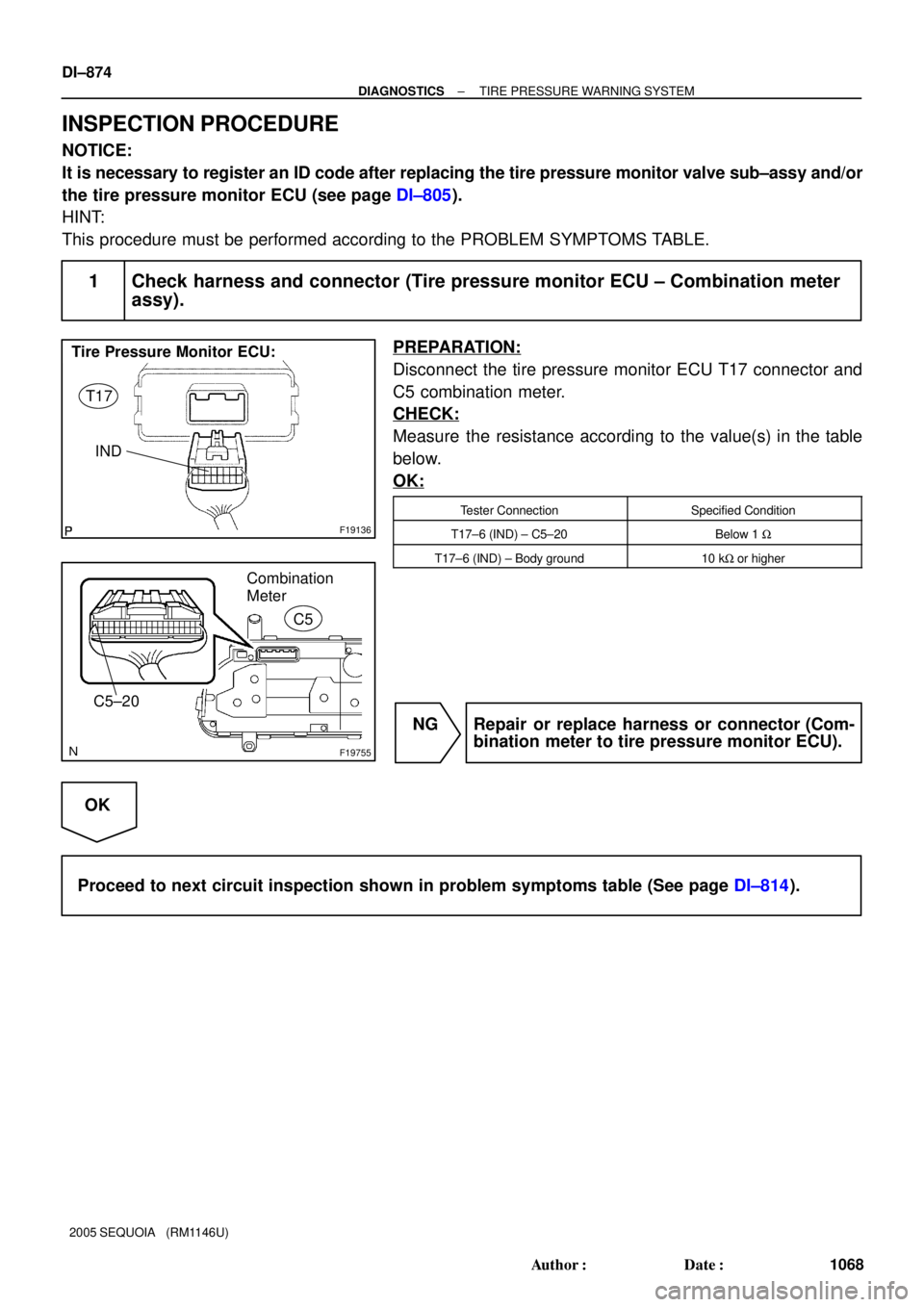
1 Check harness and connector (Tire pressure monitor ECU ± Combination meter
assy).
PREPARATION:
Disconnect the tire pressure monitor ECU T17 connector and
C5 combination meter.
CHECK:
Measure the resistance according to the value(s) in the table
below.
OK:
Tester ConnectionSpecified Condition
T17±6 (IND) ± C5±20Below 1 W
T17±6 (IND) ± Body ground10 kW or higher
NG Repair or replace harness or connector (Com-
bination meter to tire pressure monitor ECU).
OK
Proceed to next circuit inspection shown in problem symptoms table (See page DI±814).
Page 1078 of 4323

INSPECTION PROCEDURE
NOTICE:
It is necessary to reg")
F19144
Tire Pressure Warning Reset Switch
ON
OFF2
1
DI±876
± DIAGNOSTICSTIRE PRESSURE WARNING SYSTEM
1070 Author�: Date�:
2005 SEQUOIA (RM1146U)
INSPECTION PROCEDURE
NOTICE:
It is necessary to register an ID code after replacing the tire pressure monitor valve sub±assy and/or
tire pressure monitor ECU (see page DI±805).
1 Check tire pressure warning reset switch function.
CHECK:
Perform the tire pressure warning reset switch test in TEST MODE PROCEDURE (see page DI±810).
OK:
Reset switch ON: Tire pressure warning lamp comes on.
Reset switch OFF: Tire pressure warning lamp blinks.
NG Go to step 2.
OK
End.
2 Inspect tire pressure warning reset switch.
PREPARATION:
Disconnect the tire pressure warning reset switch connector.
CHECK:
Measure the resistance between terminals 1 and 2 of the tire
pressure warning reset switch when the tire pressure warning
switch is ON and OFF.
OK:
Switch ConditionSpecified Condition
ONBelow 1 W
OFF10 kW or higher
NG Replace tire pressure warning reset switch.
OK
Page 1079 of 4323
F19884
Tire Pressure Warning Reset Switch
(harness side connector)
Tire Pressure Monitor ECU:T18
CALSW
T17
± DIAGNOSTICSTIRE PRESSURE WARNING SYSTEM
DI±877
1071 Author�: Date�:
2005 SEQUOIA (RM1146U)
3 Check harness and connector (Tire pressure warning reset switch ± Tire pres-
sure monitor ECU)
PREPARATION:
Disconnect the tire pressure warning reset switch T18 connec-
tor and tire pressure monitor ECU T17 connector .
CHECK:
Measure the resistance according to the value(s) in the table
below.
OK:
Tester ConnectionSpecified Condition
T17±10 (CALSW) ± T18±1Below 1 W
T17±10 (CALSW) ± Body ground10 kW or higher
NG Repair or replace harness or connector.
OK
Replace tire pressure monitor ECU
(See page SA±20).
Page 1081 of 4323
F13970
ECU±IG Instrument
Panel J/B:
± DIAGNOSTICSTIRE PRESSURE WARNING SYSTEM
DI±879
1073 Author�: Date�:
2005 SEQUOIA (RM1146U)
INSPECTION PROCEDURE
NOTICE:
It is necessary to register an ID code after replacing the tire pressure monitor valve sub±assy and/or
the tire pressure monitor ECU (see page DI±805).
1 Inspect battery.
CHECK:
Check the battery voltage.
OK:
Voltage: 11 to 14 V
NG Check and repair charging system.
(See page CH±1)
OK
2 Inspect fuse (ECU±IG).
PREPARATION:
Remove the ECU±IG fuse from the instrument panel J/B.
CHECK:
Check continuity of the ECU±IG fuse.
OK:
Continuity
NG Check for a short in all harness and connector
connected to fuse and replace fuse.
OK