Page 1122 of 4323

VSC WARN LIGHTTurns VSC warning light ON / OFFObserve combination me-
ter
VSC / TRC OFF INDTu")
DI±920
± DIAGNOSTICSABS WITH EBD & BA & TRAC & VSC SYSTEM
111 4 Author�: Date�:
2005 SEQUOIA (RM1146U)
VSC WARN LIGHTTurns VSC warning light ON / OFFObserve combination me-
ter
VSC / TRC OFF INDTurns VSC / TRAC OFF indicator ON / OFFObserve combination me-
ter
SLIP INDI LIGHTTurns SLIP indicator light ON / OFFObserve combination me-
ter
BRAKE WRN LIGHTTurns BRAKE warning light ON / OFFObserve combination me-
ter
VSC / BR WARN BUZTurns VSC / BRAKE warning buzzer ON / OFFBuzzer can be heard
SFRR & SFRHTurns ABS solenoid SFRR & SFRH ON / OFF
Operation of solenoid
(clicking sound) can be
heard
SFLR & SFLHTurns ABS solenoid SFLR & SFLH ON / OFF
Operation of solenoid
(clicking sound) can be
heard
SRH & SRRTurns ABS solenoid SRH & SRR ON / OFF
Operation of solenoid
(clicking sound) can be
heard
SRLR & SRLHTurns ABS solenoid SRLR & SRLH ON / OFF
Operation of solenoid
(clicking sound) can be
heard
SFRH & SFLHTurns ABS solenoid SFRH & SFLH ON / OFF
Operation of solenoid
(clicking sound) can be
heard
SRCF & SRCRTurns ABS solenoid SRCF & SRCR ON / OFF
Operation of solenoid
(clicking sound) can be
heard
SRMF & SRMRTurns ABS solenoid SRMF & SRMR ON / OFF
Operation of solenoid
(clicking sound) can be
heard
Page 1123 of 4323

DIAGNOSTIC TROUBLE CODE CHART
NOTICE:
�When removing parts, turn the ignition switc")
DI93C±06
± DIAGNOSTICSABS WITH EBD & BA & TRAC & VSC SYSTEM
DI±921
111 5 Author�: Date�:
2005 SEQUOIA (RM1146U)
DIAGNOSTIC TROUBLE CODE CHART
NOTICE:
�When removing parts, turn the ignition switch OFF.
�When replacing the master cylinder, yaw rate and deceleration sensors and/or the ECU, make
sure to perform master cylinder, yaw rate and deceleration sensors' zero point calibration (See
page DI±897).
HINT:
�Using SST 09843±18040, connect terminals Tc and CG.
�If no abnormality is found when inspecting parts, inspect the ECU.
�If a trouble code is displayed during the DTC check, check the circuit listed for that code. For details
of each code, turn to the page referred to under the ºSee pageº for respective ºDTC No.º in the DTC
chart.
DTC chart of ABS system:
DTC No.
(See Page)Detection ItemTrouble Area
C0200/31*1
(DI±925)Right front wheel speed sensor signal malfunction
C0205/32*1
(DI±925)Left front wheel speed sensor signal malfunction�Right front, left front, right rear and left rear speed sensor
�Each speed sensor circuit
C0210/33*1
(DI±925)Right rear wheel speed sensor signal malfunction
�Each s eed sensor circuit
�Speed sensor rotor
�Skid control ECU
C0215/34*1
(DI±925)Left rear wheel speed sensor signal malfunction
C0226/21
(DI±932)Malfunction in ABS & VSC solenoid valves�ABS & VSC actuator
�ABS & VSC solenoid circuit
C0278/11
(DI±934)Open or short circuit in ABS & VSC relay circuit
�ABS & VSC solenoid relay
�ABS & VSC solenoid relay circuit
�ABS & VSC motor relay
�ABS & VSC motor relay circuit
C1241/41
(DI±957)Low battery positive voltage or abnormally high battery positive
voltage
�Battery
�Charging system
�Power source circuit (+BM, +BS)
�Skid control ECU
C1244/44
(DI±951)Open or short circuit in deceleration sensor circuit�Yaw rate (deceleration) sensor
�Yaw rate (deceleration) sensor circuit
C1247/47
(DI±960)Malfunction in delta S sensor
�Delta S sensor
�Delta S sensor circuit
�Skid control ECU
�Brake booster
C1249/49
(DI±963)Open circuit in stop light switch circuit
�Stop light switch
�Stop light switch circuit
�Skid control ECU
C1251/51*1
(DI±966)
Pump motor is locked
Open circuit in pump motor circuit�ABS & VSC actuator
C1337/37
(DI±975)Some tires are different in size from the other tires�Tire size
Always ON
(DI±1016)Malfunction in skid control ECU
�Battery
�Charging system
�Power source circuit
�ABS warning light circuit
�Skid control ECU
Page 1124 of 4323

*1: As long as the following operations are not performed, the ABS warning light will not go")
DI±922
± DIAGNOSTICSABS WITH EBD & BA & TRAC & VSC SYSTEM
111 6 Author�: Date�:
2005 SEQUOIA (RM1146U)
*1: As long as the following operations are not performed, the ABS warning light will not go OFF only by re-
pairing the trouble area.
(1) Drive the vehicle at 12 mph (20 km/h) for 30 seconds or more and check that the ABS warning light goes
off.
(2) Clear the DTC (See page DI±911).
HINT:
There is a possibility that the hand±held tester cannot be used when the ABS warning light is always ON.
DTC chart of VSC system:
DTC No.
(See Page)Detection ItemTrouble Area
C1201/51
(DI±936)Engine control system malfunction�Engine control system
C1202/52
(DI±937)Brake fluid level warning switch circuit
�Brake fluid level
�Brake fluid level warning switch
�Brake fluid level warning switch circuit
�Skid control ECU
�CAN1 communication system
�Translate ECU
C1203/53 *1
(DI±942)Malfunction in CAN1 communication
�Skid control ECU
�CAN1 communication system
�ECM
�Translate ECU
C1207/37
(DI±522)Reverse gear signal failureECT
C1223/43
(DI±945)Malfunction in ABS control systemABS control system
C1231/31
(DI±946)Malfunction in steering angle sensor
�Steering angle sensor
�Steering angle sensor communication circuit
�Skid control ECU
�Translate ECU
�CAN communication system
C1232/32
(DI±951)Malfunction in deceleration sensor�Yaw rate (deceleration) sensor
�Yaw rate (deceleration) sensor circuit
C1234/34
(DI±954)Malfunction in yaw rate sensor�Yaw rate (deceleration) sensor
�Yaw rate (deceleration) sensor circuit
C1310/11
(DI±969)Open or short circuit in active brake booster solenoid circuit�Brake booster
�Active brake booster solenoid circuit
C1311/12
(DI±971)Open or short circuit in brake inhibit relay circuit�Brake inhibit relay
�Brake inhibit relay circuit
1335/35
(DI±946)Malfunction in steering angle sensor communication circuit
�Steering angle sensor
�Steering angle sensor communication circuit
�Skid control ECU
�Translate ECU
�CAN1 communication system
C1340/47*2
(DI±977)Center diff. lock circuit malfunction
�Center diff. lock position switch
�Center diff. lock position switch circuit
�Center diff. lock indicator light circuit
�Translate ECU
C1360/61
(DI±983)Malfunction in master cylinder pressure sensor�Master cylinder pressure sensor
�Master cylinder pressure sensor circuit
Page 1125 of 4323
C1361/62
(DI±986)
Abnormal battery voltage of VSC sensor
�Battery
�Charging system
�Power sou")
± DIAGNOSTICSABS WITH EBD & BA & TRAC & VSC SYSTEM
DI±923
111 7 Author�: Date�:
2005 SEQUOIA (RM1146U)C1361/62
(DI±986)
Abnormal battery voltage of VSC sensor
�Battery
�Charging system
�Power source circuit
�Yaw rate (deceleration) sensor
�Skid control ECU
�Master cylinder pressure sensor
C1362/36
(DI±990)Malfunction in sensor offset value (VSC sensor system)Skid control ECU
(Perform zero point calibration)
C1363/63
(DI±991)Malfunction in booster pedal force switch�Booster pedal force switch (Active brake booster)
�Booster pedal force switch (Active brake booster) circuit
U0100/65
(DI±1075)Malfunction in vehicle CAN communication system�Vehicle CAN communication system
HINT:
There is a possibility that the hand±held tester cannot be used when the VSC TRAC warning light is always
ON.
*
1: Check DTC chart C1203/53 first, then troubleshoot according to the DTC chart of translate ECU if neces-
sary.
*
2:
4WD
DTC chart of translate ECU (When DTC ºC1201/51, C1202/52, C1203/53 or U0100/65º of VSC system
is output):
DTC No.
(See Page)Detection ItemTrouble Area
Normal code*
(DI±1013)Malfunction in ECM control system or suspension control ECU
�ECM circuit
�ECM
�Brake fluid level
�Brake fluid level warning switch circuit
�Steering angle sensor
�Translate ECU
�Skid control ECU
�Vehicle CAN
�VSC+, VSC± circuit (CAN1 communication system)
51
(DI±995)Malfunction in ECM control system�ECM
53
(DI±998)Malfunction in CAN1 communication
�VSC+, VSC± circuit (CAN1 communication system)
�Skid control ECU
�Translate ECU
58
(DI±1002)Malfunction of brake fluid level switch
�Brake fluid level warning switch circuit
�Brake fluid level warning switch
�Brake fluid reservoir level
�Translate ECU
65
(DI±1005)Malfunction 1 of vehicle CAN
�ENG+, ENG± circuit (CAN communication system)
�ECM
�Translate ECU
�Suspension control ECU
94
(DI±1009)Malfunction 2 of vehicle CAN
�ENG+, ENG± circuit (CAN communication system)
�ECM
�Translate ECU
�Suspension control ECU
Non±code
(DI±1015)Malfunction in translate ECU
�Brake warning light circuit
�Tc terminal circuit
�Translate ECU
*: Translate ECU is normal.
Page 1126 of 4323
DI±924
± DIAGNOSTICSABS WITH EBD & BA & TRAC & VSC SYSTEM
111 8 Author�: Date�:
2005 SEQUOIA (RM1146U)
If the brake warning light turns on, check that the parking brake pedal is released, the brake fluid level is
normal, and no malfunction is identified in the fluid level warning switch system.
If there is a problem with VSC, the brake warning light comes on. The possible causes of a problem are as
follows:
�2 or more wheel speed sensor failures
�Low/high voltage
�Valve failure
Page 1165 of 4323
± DIAGNOSTICSABS WITH EBD & BA & TRAC & VSC SYSTEM
DI±963
1157 Author�: Date�:
2005 SEQUOIA (RM1146U)
DTC C1249 / 49 Open Circuit in Stop Light Switch Cir-
cuit
CIRCUIT DESCRIPTION
The skid control ECU inputs the stop light switch signal and detects the status of the brake operation.
The skid control ECU has an open detection circuit. If an open in the stop lamp switch input line or GND side
stop lamp circuit is detected when the stop lamp switch is off, this DTC is output.
DTC No.DTC Detecting ConditionTrouble Area
C1249 / 49ECU terminal STP voltage is low when both ignition switch
and stop light switch are ON.�Stop light switch
�Stop light switch circuit
�Skid control ECU
DI93P±03
Page 1166 of 4323
F19773
ABS & VSC Actuator
(Skid Control ECU)
G±Y S14
Stop Light SW
I18 Ignition SW1 4 W
W±L
IG1
AM12
1
B±Y Instrument Panel J/B
2 1
1L
1F
1F1C
1C 1
2
46 STOP
AM1
ECU±IG W
4
B±R
Sub J/B No.3
3C8
3A8
B±R
B±R
J37AJ/C
J38AB8 Brake
Inhibit Relay
B±R L±OL±O
IL17
L±O
S1 38
BSW
STP S139
G±Y
IL2 13 12
3 4G±Y
4B1 1
14A
4C J11A
J10C J/C
CJ10G±Y G±W G±W
G±W
G±W B
J33
J34
H
G±W C
C
CJ44C
J45JR8 Rear Combination Light RH
1
4W±B
R7 Rear Combination Light LH
1
4 H9 High Mounted
Stop Light
A
A
A J19
J/C W±B
W±B
BD212
12W±B G±W
G±W
BD14
(*1) (*1)
(*2)(*2) W±B H9
High Mounted
Stop Light
1 2J57
J/C
BP BJ F10
Fusible
Link
Block ALT 8
5
B
Battery
*1: w/o Rear Spoiler
*2: w/ Rear Spoiler J/C
G±WJ/C
G±WSub J/B No.4
Stop Stop
DI±964
± DIAGNOSTICSABS WITH EBD & BA & TRAC & VSC SYSTEM
1158 Author�: Date�:
2005 SEQUOIA (RM1146U)
WIRING DIAGRAM
Page 1167 of 4323
F16994
STP
± DIAGNOSTICSABS WITH EBD & BA & TRAC & VSC SYSTEM
DI±965
1159 Author�: Date�:
2005 SEQUOIA (RM1146U)
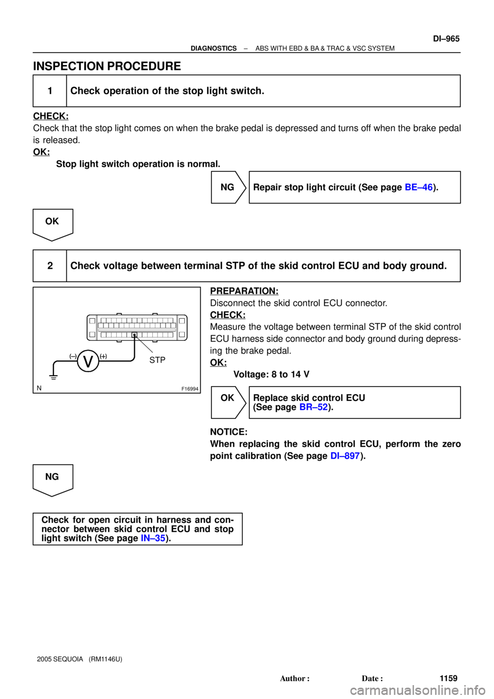
INSPECTION PROCEDURE
1 Check operation of the stop light switch.
CHECK:
Check that the stop light comes on when the brake pedal is depressed and turns off when the brake pedal
is released.
OK:
Stop light switch operation is normal.
NG Repair stop light circuit (See page BE±46).
OK
2 Check voltage between terminal STP of the skid control ECU and body ground.
PREPARATION:
Disconnect the skid control ECU connector.
CHECK:
Measure the voltage between terminal STP of the skid control
ECU harness side connector and body ground during depress-
ing the brake pedal.
OK:
Voltage: 8 to 14 V
OK Replace skid control ECU
(See page BR±52).
NOTICE:
When replacing the skid control ECU, perform the zero
point calibration (See page DI±897).
NG
Check for open circuit in harness and con-
nector between skid control ECU and stop
light switch (See page IN±35).


G±Y S14
Stop Light SW
I18 Ignition SW1 4 W
W±L
IG1
AM12
1
B±Y Instrument Panel J/B
2 1
1L
1F
1F1C
1C 1
2
46 STOP
AM1
ECU±IG W
4
B±R
Sub J/B No.3
3C8")