SR02S±08
F06730
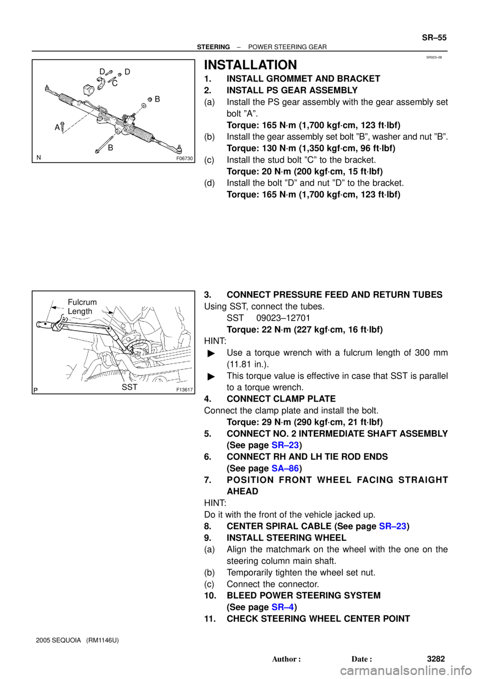
B C
A
BD D
F13617
Fulcrum
Length
SST
± STEERINGPOWER STEERING GEAR
SR±55
3282 Author�: Date�:
2005 SEQUOIA (RM1146U)
INSTALLATION
1. INSTALL GROMMET AND BRACKET
2. INSTALL PS GEAR ASSEMBLY
(a) Install the PS gear assembly with the gear assembly set
bolt ºAº.
Torque: 165 N´m (1,700 kgf´cm, 123 ft´lbf)
(b) Install the gear assembly set bolt ºBº, washer and nut ºBº.
Torque: 130 N´m (1,350 kgf´cm, 96 ft´lbf)
(c) Install the stud bolt ºCº to the bracket.
Torque: 20 N´m (200 kgf´cm, 15 ft´lbf)
(d) Install the bolt ºDº and nut ºDº to the bracket.
Torque: 165 N´m (1,700 kgf´cm, 123 ft´lbf)
3. CONNECT PRESSURE FEED AND RETURN TUBES
Using SST, connect the tubes.
SST 09023±12701
Torque: 22 N´m (227 kgf´cm, 16 ft´lbf)
HINT:
�Use a torque wrench with a fulcrum length of 300 mm
(11.81 in.).
�This torque value is effective in case that SST is parallel
to a torque wrench.
4. CONNECT CLAMP PLATE
Connect the clamp plate and install the bolt.
Torque: 29 N´m (290 kgf´cm, 21 ft´lbf)
5. CONNECT NO. 2 INTERMEDIATE SHAFT ASSEMBLY
(See page SR±23)
6. CONNECT RH AND LH TIE ROD ENDS
(See page SA±86)
7. POSITION FRONT WHEEL FACING STRAIGHT
AHEAD
HINT:
Do it with the front of the vehicle jacked up.
8. CENTER SPIRAL CABLE (See page SR±23)
9. INSTALL STEERING WHEEL
(a) Align the matchmark on the wheel with the one on the
steering column main shaft.
(b) Temporarily tighten the wheel set nut.
(c) Connect the connector.
10. BLEED POWER STEERING SYSTEM
(See page SR±4)
11. CHECK STEERING WHEEL CENTER POINT
BE0FZ±25
I24377
I24378
I04197
± BODY ELECTRICALHORN SYSTEM
BE±145
3549 Author�: Date�:
2005 SEQUOIA (RM1146U)
INSPECTION
1. INSPECT HORN SWITCH
(a) Disconnect the negative (±) terminal from the battery.
(b) Remove the left and right covers from the steering wheel.
(c) Using a torx socket wrench, loosen the 2 bolts.
(d) Pull up the horn pad and place it on the steering column,
as shown.
HINT:
Do not disconnect the connector from the horn pad.
(e) Disconnect the connector from the slip ring.
(f) Check that no continuity exists between terminal 6 of the
connector and body ground.
(g) Check that continuity exists between terminal 6 of the
connector and body ground when the horn contact plate
is pressed against the steering spoke assembly.
If continuity is not as specified, repair or replace the steering
wheel or wire harness as necessary.
(h) Install the horn pad in place and using a torx socket
wrench, torque the 2 bolts.
Torque:
7.1 N´m (72 kgf´cm, 62 in.´lbf)
(i) Install the left and right covers.
(j) Connect the negative (±) terminal to the battery.
2. INSPECT HORN OPERATION
Connect the positive (+) lead from the battery to the terminal
and negative (±) lead to the horn body and check that the horn
blows.
If operation is not as specified, replace the horn.
3. INSPECT HORN SWITCH CIRCUIT
(See page DI±1764)