Page 3141 of 4323

SA2BH±02
F14305
F14306
F16918
± SUSPENSION AND AXLECOIL SPRING AND REAR SHOCK ABSORBER
SA±137
3133 Author�: Date�:
2005 SEQUOIA (RM1146U)
REMOVAL
1. REMOVE REAR WHEELS
Torque: 110 N´m (1,150 kgf´cm, 83 ft´lbf)
2. SUPPORT REAR AXLE HOUSING WITH JACK
3. Normal Type:
REMOVE SHOCK ABSORBER
(a) Remove the bolt and disconnect the shock absorber from
the axle housing.
Torque: 87 N´m (887 kgf´cm, 64 ft´lbf)
(b) Use the same procedure described above to the other
side.
(c) While holding the piston rod, remove the nut, 2 retainers,
cushion and shock absorber.
Torque: 58 N´m (591 kgf´cm, 43 ft´lbf)
(d) Remove the 2 retainers and cushion from the shock ab-
sorber.
4. Auto Leveler Type:
REMOVE SHOCK ABSORBER
NOTICE:
When removing and installing of the shock absorber, per-
form the procedure with the shock absorber stretched
completely. The primary rod reaction force of the shock ab-
sorber is apploximately 1,000 N.
(a) Remove the bolt and disconnect the shock absorber from
the axle housing.
Torque: 87 N´m (887 kgf´cm, 64 ft´lbf)
(b) Use the same procedure described above to the other
side.
Page 3151 of 4323
SA24J±02
F14299
F14300
± SUSPENSION AND AXLEREAR UPPER AND LOWER CONTROL ARM
SA±147
3143 Author�: Date�:
2005 SEQUOIA (RM1146U)
REMOVAL
1. REMOVE REAR WHEEL
Torque: 110 N´m (1,150 kgf´cm, 83 ft´lbf)
2. SUPPORT REAR AXLE HOUSING WITH JACK
3. REMOVE UPPER CONTROL ARM
(a) Disconnect the speed sensor wire harness.
(b) Remove the bolt and brake line bracket.
Torque: 28 N´m (286 kgf´cm, 21 ft´lbf)
(c) Remove the 2 nuts, washers, bolts and upper control arm.
Torque: 140 N´m (1,428 kgf´cm, 103 ft´lbf)
HINT:
At the time of installation, after stabilizing the suspension,
torque the nuts.
4. REMOVE LOWER CONTROL ARM
(a) Remove the bolt and parking brake cable bracket.
Torque: 26 N´m (265 kgf´cm, 19 ft´lbf)
(b) Remove the 2 nuts, bolts and lower control arm.
Torque: 130 N´m (1,326 kgf´cm, 96 ft´lbf)
HINT:
At the time of installation, after stabilizing the suspension,
torque the nuts.
Page 3154 of 4323
SA17F±04
F14302
F14303
SA±150
± SUSPENSION AND AXLEREAR STABILIZER BAR
3146 Author�: Date�:
2005 SEQUOIA (RM1146U)
REMOVAL
1. REMOVE REAR WHEELS
Torque: 110 N´m (1,150 kgf´cm, 83 ft´lbf)
2. SUPPORT REAR AXLE HOUSING WITH JACK
3. REMOVE STABILIZER BAR LINKS
(a) Remove the 2 nuts and stabilizer bar link.
Torque: 69 N´m (704 kgf´cm, 51 ft´lbf)
HINT:
If the ball joint stud turns together with the nut, use a hexagon
wrench to hold the stud.
(b) Use the same procedure described above to the other
side.
4. REMOVE STABILIZER BAR FROM REAR AXLE
HOUSING
(a) Remove the 4 bolts and stabilizer bar with the bushings
and brackets.
Torque: 37 N´m (377 kgf´cm, 27 ft´lbf)
(b) Remove the 2 brackets and 2 bushings from the stabilizer
bar.
Page 3203 of 4323
BR10M±03
F07752
SST
F07753
BR±28
± BRAKEFRONT BRAKE CALIPER
3195 Author�: Date�:
2005 SEQUOIA (RM1146U)
REMOVAL
1. REMOVE FRONT WHEEL
Torque: 110 N´m (1,122 kgf´cm, 81 ft´lbf)
2. DISCONNECT BRAKE LINE
Using SST, disconnect the brake line. Use a container to catch
the brake fluid.
SST 09023±00101
Torque: 15 N´m (155 kgf´cm, 11 ft´lbf)
3. REMOVE CALIPER
Remove the 2 mounting bolts and caliper.
Torque: 123 N´m (1,250 kgf´cm, 90 ft´lbf)
4. REMOVE CLIP, 2 PINS AND ANTI±RATTLE SPRING
5. REMOVE 2 PADS WITH 4 ANTI±SQUEAL SHIMS
Page 3212 of 4323
BR0JS±14
F13316
± BRAKEREAR BRAKE CALIPER
BR±37
3204 Author�: Date�:
2005 SEQUOIA (RM1146U)
REMOVAL
1. REMOVE REAR WHEEL
Torque: 110 N´m (1,122 kgf´cm, 81 ft´lbf)
2. DISCONNECT FLEXIBLE HOSE
Remove the union bolt and gasket from the caliper, then discon-
nect the flexible hose from the caliper. Use a container to catch
brake fluid as it drains out.
Torque: 31 N´m (320 kgf´cm, 23 ft´lbf)
HINT:
Securely set the flexible hose between the projections of the
caliper.
3. REMOVE CALIPER
(a) Remove the 2 sliding pins.
Torque: 88 N´m (900 kgf´cm, 65 ft´lbf)
(b) Remove the caliper from the torque plate.
4. REMOVE 2 BRAKE PADS WITH ANTI±SQUEAL SHIM
5. REMOVE 4 PAD SUPPORT PLATES
Page 3218 of 4323

BR1NF±02
F13327
F13323
F13324
± BRAKEPARKING BRAKE
BR±43
3210 Author�: Date�:
2005 SEQUOIA (RM1146U)
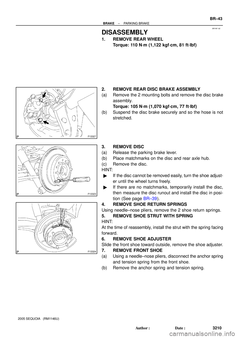
DISASSEMBLY
1. REMOVE REAR WHEEL
Torque: 110 N´m (1,122 kgf´cm, 81 ft´lbf)
2. REMOVE REAR DISC BRAKE ASSEMBLY
(a) Remove the 2 mounting bolts and remove the disc brake
assembly.
Torque: 105 N´m (1,070 kgf´cm, 77 ft´lbf)
(b) Suspend the disc brake securely and so the hose is not
stretched.
3. REMOVE DISC
(a) Release the parking brake lever.
(b) Place matchmarks on the disc and rear axle hub.
(c) Remove the disc.
HINT:
�If the disc cannot be removed easily, turn the shoe adjust-
er until the wheel turns freely.
�If there are no matchmarks, temporarily install the disc,
then measure the disc runout and install the disc in posi-
tion (See page BR±39).
4. REMOVE SHOE RETURN SPRINGS
Using needle±nose pliers, remove the 2 shoe return springs.
5. REMOVE SHOE STRUT WITH SPRING
HINT:
At the time of reassembly, install the strut with the spring facing
forward.
6. REMOVE SHOE ADJUSTER
Slide the front shoe toward outside, remove the shoe adjuster.
7. REMOVE FRONT SHOE
(a) Using a needle±nose pliers, disconnect the anchor spring
and tension spring from the front shoe.
(b) Remove the anchor spring and tension spring.
Page 3231 of 4323
BR0A3±04
F08186
BR±56
± BRAKEFRONT SPEED SENSOR
3223 Author�: Date�:
2005 SEQUOIA (RM1146U)
REMOVAL
1. REMOVE FRONT WHEEL
Torque: 110 N´m (1,122 kgf´cm, 81 ft´lbf)
2. DISCONNECT SPEED SENSOR CONNECTOR
3. REMOVE SPEED SENSOR
(a) Remove the clips and 3 clamp bolts holding the sensor
harness from the frame, upper arm and steering knuckle.
Torque: 8.0 N´m (82 kgf´cm, 71 in.´lbf)
(b) Remove the bolt and speed sensor from the steering
knuckle.
Torque: 8.0 N´m (82 kgf´cm, 71 in.´lbf)
Page 3259 of 4323

F13260
F17896
BMatchmarks
A
F19948
Mark
SR±24
± STEERINGTILT STEERING COLUMN
3251 Author�: Date�:
2005 SEQUOIA (RM1146U)
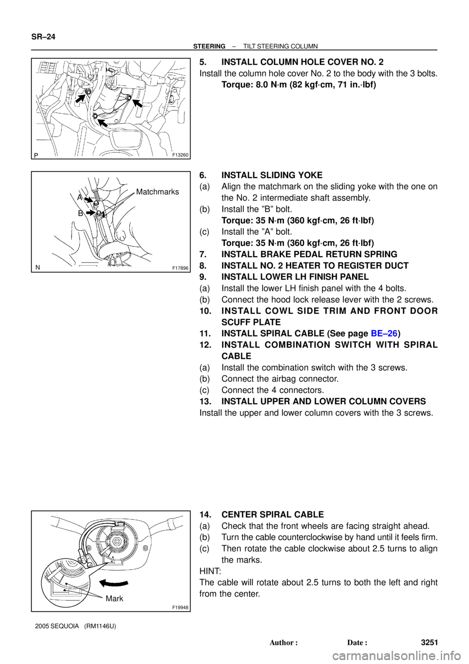
5. INSTALL COLUMN HOLE COVER NO. 2
Install the column hole cover No. 2 to the body with the 3 bolts.
Torque: 8.0 N´m (82 kgf´cm, 71 in.´lbf)
6. INSTALL SLIDING YOKE
(a) Align the matchmark on the sliding yoke with the one on
the No. 2 intermediate shaft assembly.
(b) Install the ºBº bolt.
Torque: 35 N´m (360 kgf´cm, 26 ft´lbf)
(c) Install the ºAº bolt.
Torque: 35 N´m (360 kgf´cm, 26 ft´lbf)
7. INSTALL BRAKE PEDAL RETURN SPRING
8. INSTALL NO. 2 HEATER TO REGISTER DUCT
9. INSTALL LOWER LH FINISH PANEL
(a) Install the lower LH finish panel with the 4 bolts.
(b) Connect the hood lock release lever with the 2 screws.
10. INSTALL COWL SIDE TRIM AND FRONT DOOR
SCUFF PLATE
11. INSTALL SPIRAL CABLE (See page BE±26)
12. INSTALL COMBINATION SWITCH WITH SPIRAL
CABLE
(a) Install the combination switch with the 3 screws.
(b) Connect the airbag connector.
(c) Connect the 4 connectors.
13. INSTALL UPPER AND LOWER COLUMN COVERS
Install the upper and lower column covers with the 3 screws.
14. CENTER SPIRAL CABLE
(a) Check that the front wheels are facing straight ahead.
(b) Turn the cable counterclockwise by hand until it feels firm.
(c) Then rotate the cable clockwise about 2.5 turns to align
the marks.
HINT:
The cable will rotate about 2.5 turns to both the left and right
from the center.