Page 3033 of 4323

FRONT WHEEL HUB BOLT
REPLACEMENT
1. REMOVE FRONT WHEEL
2. RE")
SA24P±03
F07264
R13372
SST
R13373WasherNut
± SUSPENSION AND AXLEFRONT WHEEL HUB BOLT
SA±29
3025 Author�: Date�:
2005 SEQUOIA (RM1146U)
FRONT WHEEL HUB BOLT
REPLACEMENT
1. REMOVE FRONT WHEEL
2. REMOVE BRAKE CALIPER AND DISC
(a) Remove the bolt and brake line clamp from the steering
knuckle.
(b) Remove the 2 bolts, brake caliper and disc.
(c) Support the brake caliper securely.
3. REMOVE HUB BOLT
Using SST and a screwdriver or an equivalent, remove the hub
bolt.
SST 09650±17011
4. INSTALL HUB BOLT
(a) Install a washer and nut to a new hub bolt as shown in the
illustration.
(b) Using a screwdriver or an equivalent to hold, install the
hub bolt by torquing the nut.
(c) Remove the nut and washer.
5. INSTALL BRAKE DISC AND CALIPER
(a) Install the brake disc, caliper and 2 bolts.
Torque: 123 N´m (1,250 kgf´cm, 90 ft´lbf)
(b) Install the brake line clamp to the steering knuckle with the
bolt.
Torque: 28 N´m (285 kgf´cm, 21 ft´lbf)
6. INSTALL FRONT WHEEL
Torque: 110 N´m (1,150 kgf´cm, 83 ft´lbf)
7. DEPRESS BRAKE PEDAL SEVERAL TIMES
Page 3074 of 4323
SA182±06
SA±70
± SUSPENSION AND AXLEFRONT SHOCK ABSORBER
3066 Author�: Date�:
2005 SEQUOIA (RM1146U)
INSTALLATION
1. INSTALL SHOCK ABSORBER WITH COIL SPRING
(a) Install the upper side of the shock absorber to the chassis frame with the 3 nuts.
Torque: 64 N´m (650 kgf´cm, 47 ft´lbf)
(b) Connect the lower side of the shock absorber to the lower suspension arm with the bolt, washer and
nut.
Torque: 135 N´m (1,400 kgf´cm, 100 ft´lbf)
2. INSTALL FRONT WHEEL
Torque: 110 N´m (1,150 kgf´cm, 83 ft´lbf)
Page 3078 of 4323

INSTALLATION
1. INSTALL UPPER SUSPENSION ARM
Install the upper suspension arm with the 2")
SA187±06
SA±74
± SUSPENSION AND AXLEFRONT UPPER SUSPENSION ARM
3070 Author�: Date�:
2005 SEQUOIA (RM1146U)
INSTALLATION
1. INSTALL UPPER SUSPENSION ARM
Install the upper suspension arm with the 2 washers, bolt and nut.
Torque: 98 N´m (1,000 kgf´cm, 72 ft´lbf)
HINT:
After stabilizing the suspension, torque the nut.
2. INSTALL BRAKE AND FUEL LINE CLAMP
Torque: 5.5 N´m (56 kgf´cm, 49 in.´lbf)
3. INSTALL FENDER APRON SEAL REAR
4. CONNECT UPPER BALL JOINT
(a) Connect the upper ball joint to the upper suspension arm.
(b) Install the nut and a new cotter pin.
If the holes for the cotter pin are not aligned, tighten the nut further up to 60°.
Torque: 105 N´m (1,100 kgf´cm, 77 ft´lbf)
5. CONNECT SPEED SENSOR WIRE HARNESS CLAMPS
Torque: 8.0 N´m (82 kgf´cm, 71 in.´lbf)
6. INSTALL SHOCK ABSORBER WITH COIL SPRING (See page SA±70)
7. CHECK FRONT WHEEL ALIGNMENT (See page SA±4)
8. PERFORM ZERO POINT CALIBRATION OF STEERING ANGLE, MASTER CYLINDER PRES-
SURE, YAW RATE AND DECELERATION SENSORS (See page DI±897)
Page 3084 of 4323

INSTALLATION
1. INSTALL LOWER SUSPENSION ARM TO")
SA23Y±05
R13282
MatchmarksMatchmarks
F07278
AC
B SA±80
± SUSPENSION AND AXLEFRONT LOWER SUSPENSION ARM
3076 Author�: Date�:
2005 SEQUOIA (RM1146U)
INSTALLATION
1. INSTALL LOWER SUSPENSION ARM TO CHASSIS
FRAME
Install the lower suspension arm with the 2 cams, bolts and cam
plates while slightly shifting the power steering gear rearward.
Torque: 130 N´m (1,325 kgf´cm, 96 ft´lbf)
NOTICE:
Do not damage the power steering gear tubes.
HINT:
After stabilizing the suspension, align the matchmarks on the
front and rear cam plates and chassis frame, and torque the
bolts.
2. CONNECT LOWER BALL JOINT TO LOWER SUSPEN-
SION ARM
Connect the lower ball joint and install the nut and a new cotter
pin.
Torque: 159 N´m (1,621 kgf´cm, 117 ft´lbf)
If the holes for the cotter pin are not aligned, tighten the nut fur-
ther up to 60°.
3. CONNECT SHOCK ABSORBER TO LOWER SUSPEN-
SION ARM
Torque: 135 N´m (1,400 kgf´cm, 100 ft´lbf)
4. CONNECT STABILIZER BAR LINK TO LOWER SUS-
PENSION ARM
Torque: 69 N´m (700 kgf´cm, 51 ft´lbf)
HINT:
If the ball joint turns together with the nut, use a hexagon (6 mm)
wrench to hold the stud.
5. INSTALL POWER STEERING GEAR
Torque:
A bolt: 165 N´m (1,700 kgf´cm, 122 ft´lbf)
B nut: 130 N´m (1,350 kgf´cm, 96 ft´lbf)
C bolt and nut: 165 N´m (1,700 kgf´cm, 122 ft´lbf)
6. CONNECT RH AND LH TIE ROD ENDS
Connect the RH and LH tie rod ends to the lower ball joints with
the nuts and new cotter pins.
Torque: 91 N´m (930 kgf´cm, 67 ft´lbf)
If the holes for the cotter pin are not aligned, tighten the nut fur-
ther up to 60°.
7. INSTALL RH AND LH FRONT WHEELS
Torque: 110 N´m (1,150 kgf´cm, 83 ft´lbf)
8. CHECK FRONT WHEEL ALIGNMENT (See page
SA±4)
9. PERFORM ZERO POINT CALIBRATION OF STEER-
ING ANGLE, MASTER CYLINDER PRESSURE, YAW
RATE AND DECELERATION SENSORS (See page
DI±897)
Page 3093 of 4323

INSTALLATION
1. INSTALL LOWER BALL JOINT
(a) While lifting the upper suspension arm and stee")
SA247±07
± SUSPENSION AND AXLEFRONT LOWER BALL JOINT
SA±89
3085 Author�: Date�:
2005 SEQUOIA (RM1146U)
INSTALLATION
1. INSTALL LOWER BALL JOINT
(a) While lifting the upper suspension arm and steering knuckle, install the lower ball joint.
(b) Temporarily install the 4 bolts to the lower ball joint.
(c) Install the set nut to hold the lower ball joint to the lower suspension arm and a new cotter pin.
Torque: 159 N´m (1,621 kgf´cm, 117 ft´lbf)
If the holes for the cotter pin are not aligned, tighten the nut further up to 60°.
2. CONNECT TIE ROD END
Connect the tie rod end to the lower ball joint with the nut and a new cotter pin.
Torque: 91 N´m (930 kgf´cm, 67 ft´lbf)
If the holes for the cotter pin are not aligned, tighten the nut further up to 60°.
3. TIGHTEN LOWER BALL JOINT SET 4 BOLTS
Torque: 65 N´m (663 kgf´cm, 48 ft´lbf)
4. INSTALL FRONT WHEEL
Torque: 110 N´m (1,150 kgf´cm, 83 ft´lbf)
5. CHECK FRONT WHEEL ALIGNMENT (See page SA±4)
6. PERFORM ZERO POINT CALIBRATION OF STEERING ANGLE, MASTER CYLINDER PRES-
SURE, YAW RATE AND DECELERATION SENSORS (See page DI±897)
Page 3099 of 4323

REMOVAL
1. REMOVE REAR WHEEL
Torque: 110 N´m (1,150 kgf´cm, 83 ft´lbf)")
SA17S±04
F14273
SST
F14274
F14275
± SUSPENSION AND AXLEREAR AXLE SHAFT
SA±95
3091 Author�: Date�:
2005 SEQUOIA (RM1146U)
REMOVAL
1. REMOVE REAR WHEEL
Torque: 110 N´m (1,150 kgf´cm, 83 ft´lbf)
2. DISCONNECT BRAKE LINE
Using SST, disconnect the brake line and remove the clip.
SST 09023±00101
Torque: 15.5 N´m (158 kgf´cm, 11 ft´lbf)
3. REMOVE BRAKE CALIPER AND DISC
Remove the 2 bolts, brake caliper and disc.
Torque: 105 N´m (1,070 kgf´cm, 77 ft´lbf)
4. CHECK BEARING BACKLASH AND AXLE SHAFT
DEVIATION
(a) Using a dial indicator, check the backlash in the bearing
shaft direction.
Maximum: 0.6 mm (0.024 in.)
If the backlash exceeds the maximum, replace the bearing.
(b) Using a dial indicator, check the deviation at the surface
of the axle shaft outside the hub bolt.
Maximum: 0.1 mm (0.0040 in.)
If the deviation exceeds the maximum, replace the axle shaft.
5. REMOVE PARKING BRAKE ASSEMBLY
(a) Remove the parking brake assembly (See page
BR±43).
(b) Remove the 2 bolts and pull out the parking brake cable
from the backing plate.
Torque: 8.0 N´m (82 kgf´cm, 71 in.´lbf)
(c) Use the same procedures described above to the other
side.
Page 3107 of 4323
SA24C±02
F14274
F14290
Nut
Washer
± SUSPENSION AND AXLEREAR WHEEL HUB BOLT
SA±103
3099 Author�: Date�:
2005 SEQUOIA (RM1146U)
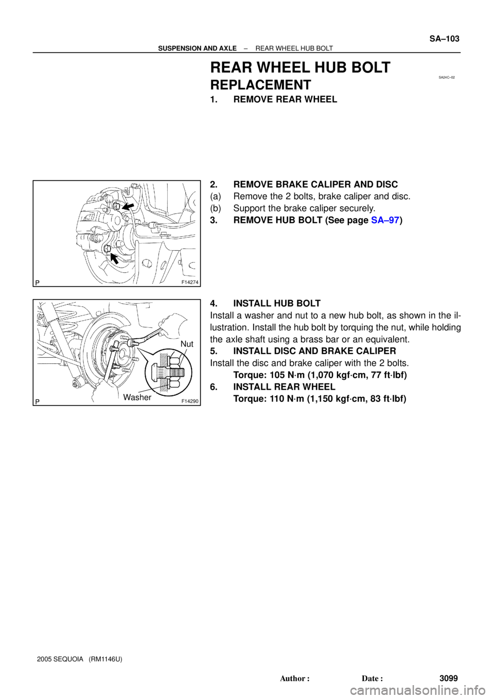
REAR WHEEL HUB BOLT
REPLACEMENT
1. REMOVE REAR WHEEL
2. REMOVE BRAKE CALIPER AND DISC
(a) Remove the 2 bolts, brake caliper and disc.
(b) Support the brake caliper securely.
3. REMOVE HUB BOLT (See page SA±97)
4. INSTALL HUB BOLT
Install a washer and nut to a new hub bolt, as shown in the il-
lustration. Install the hub bolt by torquing the nut, while holding
the axle shaft using a brass bar or an equivalent.
5. INSTALL DISC AND BRAKE CALIPER
Install the disc and brake caliper with the 2 bolts.
Torque: 105 N´m (1,070 kgf´cm, 77 ft´lbf)
6. INSTALL REAR WHEEL
Torque: 110 N´m (1,150 kgf´cm, 83 ft´lbf)
Page 3115 of 4323

REMOVAL
1. REMOVE 2 REAR WHEELS
Torque: 110 N´m (1,122 kgf´cm")
SA24E±02
F14273
SST
F14274
F14276
± SUSPENSION AND AXLEREAR DIFFERENTIAL CARRIER
SA±111
3107 Author�: Date�:
2005 SEQUOIA (RM1146U)
REMOVAL
1. REMOVE 2 REAR WHEELS
Torque: 110 N´m (1,122 kgf´cm, 81 ft´lbf)
2. DRAIN HYPOID GEAR OIL
Torque: 49 N´m (500 kgf´cm, 36 ft´lbf)
3. DISCONNECT BRAKE LINES
(a) Using SST, disconnect the brake line and remove the clip.
SST 09023±00100
Torque: 15.5 N´m (158 kgf´cm, 11 ft´lbf)
(b) Use the same procedure described above to the other
side.
4. REMOVE BRAKE CALIPER AND DISC
(a) Remove the 2 bolts, brake caliper and disc.
Torque: 105 N´m (1,070 kgf´cm, 77 ft´lbf)
(b) Use the same procedure described above to the other
side.
5. REMOVE PARKING BRAKE ASSEMBLY
(a) Remove the parking brake assembly (See page
BR±43).
(b) Remove the 2 bolts and pull out the parking brake cable
from the backing plate.
Torque: 8.0 N´m (82 kgf´cm, 71 in.´lbf)
(c) Use the same procedures described above to the other
side.
6. REMOVE AXLE SHAFTS
(a) Remove the 4 nuts.
Torque: 122 N´m (1,244 kgf´cm, 90 ft´lbf)
(b) Pull out the axle shaft and remove the O±ring.
NOTICE:
Be careful not to damage the oil seal.
(c) Use the same procedures described above to the other
side.