Page 3392 of 4323
± SUPPLEMENTAL RESTRAINT SYSTEMCURTAIN SHIELD AIRBAG SENSOR ASSEMBLY
RS±101
3384 Author�: Date�:
2005 SEQUOIA (RM1146U)
8. PERFORM INITIALIZATION (SEE PAGE BE±77)
Some system need initialization when disconnecting the cable
from the negative battery terminal.
9. INSPECT SRS WARNING LIGHT (SEE PAGE DI±1137)
Page 3400 of 4323
± SUPPLEMENTAL RESTRAINT SYSTEMSEAT POSITION SENSOR ASSEMBLY
RS±109
3392 Author�: Date�:
2005 SEQUOIA (RM1146U)
6. Separate type (Manual adjuster):
INSTALL SEAT CUSHION OUTER SHIELD
(SEE PAGE BO±130)
7. Separate type (Manual adjuster):
INSTALL VERTICAL ADJUSTER HANDLE
(SEE PAGE BO±130)
8. Separate type (Manual adjuster):
INSTALL FRONT SEAT ASSEMBLY LH
(SEE PAGE BO±134)
9. CONNECT CABLE TO NEGATIVE BATTERY TERMI-
NAL
10. PERFORM INITIALIZATION (SEE PAGE BE±77)
Some system need initialization when disconnecting the cable
from the negative battery terminal.
11. INSPECT SRS WARNING LIGHT (SEE PAGE DI±1137)
Page 3405 of 4323

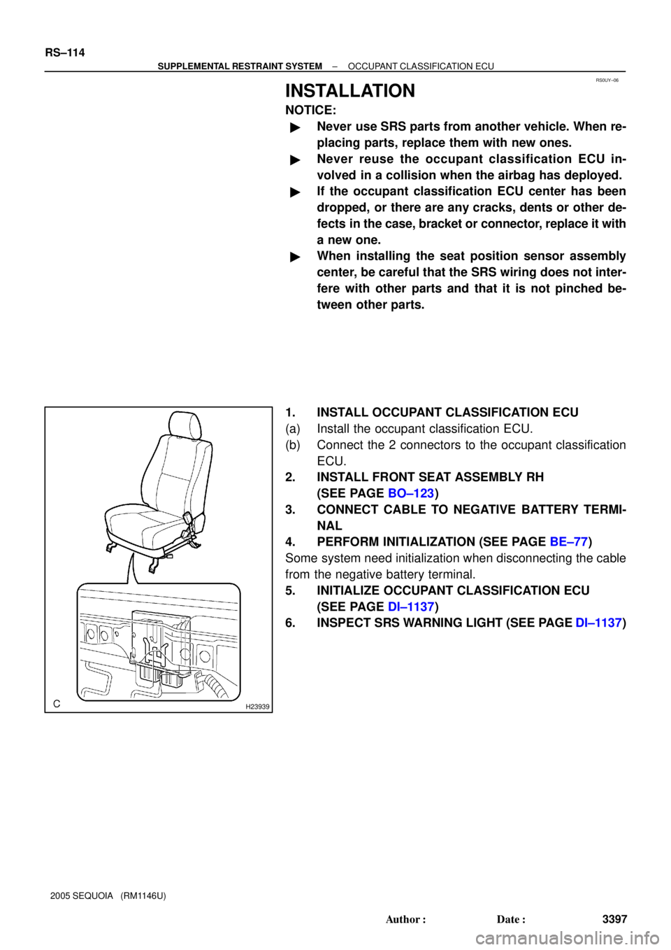
RS0UY±06
H23939
RS±114
± SUPPLEMENTAL RESTRAINT SYSTEMOCCUPANT CLASSIFICATION ECU
3397 Author�: Date�:
2005 SEQUOIA (RM1146U)
INSTALLATION
NOTICE:
�Never use SRS parts from another vehicle. When re-
placing parts, replace them with new ones.
�Never reuse the occupant classification ECU in-
volved in a collision when the airbag has deployed.
�If the occupant classification ECU center has been
dropped, or there are any cracks, dents or other de-
fects in the case, bracket or connector, replace it with
a new one.
�When installing the seat position sensor assembly
center, be careful that the SRS wiring does not inter-
fere with other parts and that it is not pinched be-
tween other parts.
1. INSTALL OCCUPANT CLASSIFICATION ECU
(a) Install the occupant classification ECU.
(b) Connect the 2 connectors to the occupant classification
ECU.
2. INSTALL FRONT SEAT ASSEMBLY RH
(SEE PAGE BO±123)
3. CONNECT CABLE TO NEGATIVE BATTERY TERMI-
NAL
4. PERFORM INITIALIZATION (SEE PAGE BE±77)
Some system need initialization when disconnecting the cable
from the negative battery terminal.
5. INITIALIZE OCCUPANT CLASSIFICATION ECU
(SEE PAGE DI±1137)
6. INSPECT SRS WARNING LIGHT (SEE PAGE DI±1137)
Page 3409 of 4323
RS11Z±01
H23940Claw RS±118
± SUPPLEMENTAL RESTRAINT SYSTEMRSCA OFF SWITCH
3401 Author�: Date�:
2005 SEQUOIA (RM1146U)
INSTALLATION
1. INSTALL SWITCH BASE
(a) Connect the connectors.
(b) Engage the 3 claws to install the switch base.
2. INSTALL LOWER FINISH PANEL (SEE PAGE BO±97)
3. CONNECT CABLE TO NEGATIVE BATTERY TERMI-
NAL
4. PERFORM INITIALIZATION (SEE PAGE BE±77)
Some system need initialization when disconnecting the cable
from the negative battery terminal.
5. INSPECT SRS WARNING LIGHT (SEE PAGE DI±1137)
Page 3410 of 4323
RS0BU±10
H23906
Front Airbag Sensor (LH)Front Airbag
Sensor (RH)Front Passenger
Airbag Assembly (RH)
Seat Belt
Pretensioner (RH)
Airbag Sensor Assembly Seat Belt Pretensioner (LH) Spiral CableCurtain Shield
Airbag Assembly (RH)
Side Airbag
Assembly (RH) (*1)
Side Airbag Sensor
Assembly (RH) (*1)
Side Airbag Assembly (LH) (*1) Side Airbag Sensor
Assembly (LH) (*1)
Curtain Shield Airbag
Assembly (LH) (*1)
Combination Meter
(Warning Light)
Steering Wheel Pad
(With Airbag)
Curtain Shield Airbag
Sensor Assembly (LH) (*1)
Curtain Shield Airbag
Sensor Assembly
(RH) (*1)RSCA OFF
Switch (*1)
Occupant Classification
ECU (*1)
(*1) w/ Side Airbag and Curtain Shield Airbag
± SUPPLEMENTAL RESTRAINT SYSTEMWIRE HARNESS AND CONNECTOR
RS±119
3402 Author�: Date�:
2005 SEQUOIA (RM1146U)
WIRE HARNESS AND CONNECTOR
LOCATION
Page 3414 of 4323

BE19B±08
BE±2
± BODY ELECTRICALTROUBLESHOOTING
3406 Author�: Date�:
2005 SEQUOIA (RM1146U)
TROUBLESHOOTING
PROBLEM SYMPTOMS TABLE
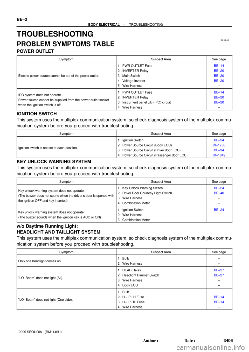
POWER OUTLET
SymptomSuspect AreaSee page
Electric power source cannot be out of the power outlet.
1. PWR OUTLET Fuse
2. INVERTER Relay
3. Main Switch
4. Voltage Inverter
5. Wire HarnessBE±14
BE±20
BE±20
BE±20
±
IPO system does not operate.
Power source cannot be supplied from the power outlet socket
when the ignition switch is off.1. PWR OUTLET Fuse
2. INVERTER Relay
3. Instrument panel J/B (IPO) circuit
4. Wire HarnessBE±14
BE±20
BE±20
±
IGNITION SWITCH
This system uses the multiplex communication system, so check diagnosis system of the multiplex commu-
nication system before you proceed with troubleshooting.
SymptomSuspect AreaSee page
Ignition switch is not set to each position.
1. Ignition Switch
2. Power Source Circuit (Body ECU)
3. Power Source Circuit (Driver door ECU)
4. Power Source Circuit (Passenger door ECU)BE±24
DI±1700
BE±34
DI±1849
KEY UNLOCK WARNING SYSTEM
This system uses the multiplex communication system, so check diagnosis system of the multiplex commu-
nication system before you proceed with troubleshooting.
SymptomSuspect AreaSee page
Key unlock warning system does not operate.
(The buzzer does not sound when the driver's door is opened with
the ignition OFF and key inserted)1. Key Unlock Warning Switch
2. Driver Door Courtesy Light Switch
3. Wire Harness
4. Combination MeterBE±24
BE±40
±
±
Key unlock warning system does not operate.
(The buzzer sounds when the ignition key is ACC or ON)1. Ignition Switch
2. Wire Harness
3. Combination MeterBE±24
±
±
w/o Daytime Running Light:
HEADLIGHT AND TAILLIGHT SYSTEM
This system uses the multiplex communication system, so check diagnosis system of the multiplex commu-
nication system before you proceed with troubleshooting.
SymptomSuspect AreaSee page
Only one headlight comes on.1. Bulb
2. Wire Harness±
±
ºLO±Beamº does not light (All).
1. HEAD Relay
2. Headlight Dimmer Switch
3. Wire Harness
4. Body ECUBE±27
BE±27
±
±
ºLO±Beamº does not light (One side).
1. Bulb
2. H±LP LH Fuse
3. H±LP RH Fuse
4. Wire Harness±
BE±14
BE±14
±
Page 3417 of 4323

± BODY ELECTRICALTROUBLESHOOTING
BE±5
3409 Author�: Date�:
2005 SEQUOIA (RM1146U) Taillight does not go off when light control switch is in OFF posi-
tion.
1. TAILLIGHT Relay
2. Light Control Switch
3. Wire Harness
4. Body ECUBE±27
BE±27
±
±
Headlight does not come on when engine is running and light
control switch is in OFF position .
1. ECU±B Fuse
2. MAIN Fuse
3. HEAD Relay
4. DRL Fuse
5. DRL No. 4 Relay
6. DIMMER Relay
7. Parking Brake Switch
8. Wire Harness
9. Body ECUBE±14
BE±14
BE±27
BE±14
BE±27
BE±55
BE±55
±
±
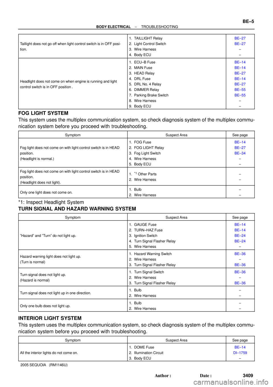
FOG LIGHT SYSTEM
This system uses the multiplex communication system, so check diagnosis system of the multiplex commu-
nication system before you proceed with troubleshooting.
SymptomSuspect AreaSee page
Fog light does not come on with light control switch is in HEAD
position.
(Headlight is normal.)
1. FOG Fuse
2. FOG LIGHT Relay
3. Fog Light Switch
4. Wire Harness
5. Body ECUBE±14
BE±27
BE±34
±
±
Fog light does not come on with light control switch is in HEAD
position.
(Headlight does not light).1.*1 Other Parts
2. Wire Harness±
±
Only one light does not come on.1. Bulb
2. Wire Harness±
±
*1: Inspect Headlight System
TURN SIGNAL AND HAZARD WARNING SYSTEM
SymptomSuspect AreaSee page
ºHazardº and ºTurnº do not light up.
1. GAUGE Fuse
2. TURN±HAZ Fuse
3. Ignition Switch
4. Turn Signal Flasher Relay
5. Wire HarnessBE±14
BE±14
BE±24
BE±24
±
Hazard warning light does not light up.
(Turn is normal)1. Hazard Warning Switch
2. Wire Harness
3. Turn Signal Flasher RelayBE±36
±
BE±36
Turn signal does not light up.
(Hazard is normal)1. Turn Signal Switch
2. Wire Harness
3. Turn Signal Flasher RelayBE±36
±
BE±36
Turn signal does not light up in one direction.1. Bulb
2. Wire Harness±
±
Only one bulb does not light up.1. Bulb
2. Wire Harness±
±
INTERIOR LIGHT SYSTEM
This system uses the multiplex communication system, so check diagnosis system of the multiplex commu-
nication system before you proceed with troubleshooting.
SymptomSuspect AreaSee page
All the interior lights do not come on.
1. DOME Fuse
2. Illumination Circuit
3. Body ECUBE±14
DI±1759
±
Page 3421 of 4323

± BODY ELECTRICALTROUBLESHOOTING
BE±9
3413 Author�: Date�:
2005 SEQUOIA (RM1146U)
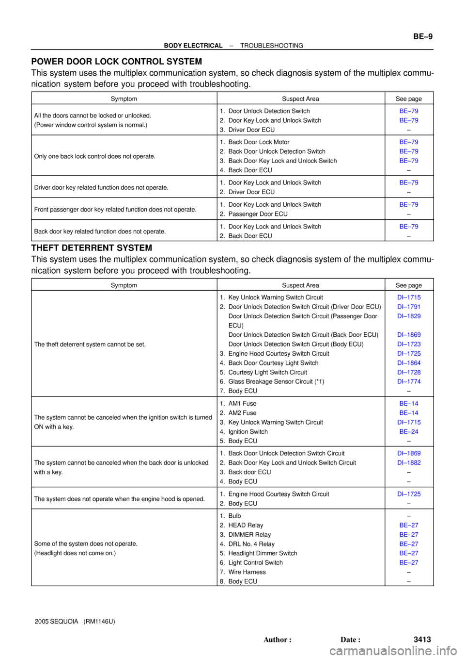
POWER DOOR LOCK CONTROL SYSTEM
This system uses the multiplex communication system, so check diagnosis system of the multiplex commu-
nication system before you proceed with troubleshooting.
SymptomSuspect AreaSee page
All the doors cannot be locked or unlocked.
(Power window control system is normal.)1. Door Unlock Detection Switch
2. Door Key Lock and Unlock Switch
3. Driver Door ECUBE±79
BE±79
±
Only one back lock control does not operate.
1. Back Door Lock Motor
2. Back Door Unlock Detection Switch
3. Back Door Key Lock and Unlock Switch
4. Back Door ECUBE±79
BE±79
BE±79
±
Driver door key related function does not operate.1. Door Key Lock and Unlock Switch
2. Driver Door ECUBE±79
±
Front passenger door key related function does not operate.1. Door Key Lock and Unlock Switch
2. Passenger Door ECUBE±79
±
Back door key related function does not operate.1. Door Key Lock and Unlock Switch
2. Back Door ECUBE±79
±
THEFT DETERRENT SYSTEM
This system uses the multiplex communication system, so check diagnosis system of the multiplex commu-
nication system before you proceed with troubleshooting.
SymptomSuspect AreaSee page
The theft deterrent system cannot be set.
1. Key Unlock Warning Switch Circuit
2. Door Unlock Detection Switch Circuit (Driver Door ECU)
Door Unlock Detection Switch Circuit (Passenger Door
ECU)
Door Unlock Detection Switch Circuit (Back Door ECU)
Door Unlock Detection Switch Circuit (Body ECU)
3. Engine Hood Courtesy Switch Circuit
4. Back Door Courtesy Light Switch
5. Courtesy Light Switch Circuit
6. Glass Breakage Sensor Circuit (*1)
7. Body ECUDI±1715
DI±1791
DI±1829
DI±1869
DI±1723
DI±1725
DI±1864
DI±1728
DI±1774
±
The system cannot be canceled when the ignition switch is turned
ON with a key.
1. AM1 Fuse
2. AM2 Fuse
3. Key Unlock Warning Switch Circuit
4. Ignition Switch
5. Body ECUBE±14
BE±14
DI±1715
BE±24
±
The system cannot be canceled when the back door is unlocked
with a key.
1. Back Door Unlock Detection Switch Circuit
2. Back Door Key Lock and Unlock Switch Circuit
3. Back door ECU
4. Body ECUDI±1869
DI±1882
±
±
The system does not operate when the engine hood is opened.1. Engine Hood Courtesy Switch Circuit
2. Body ECUDI±1725
±
Some of the system does not operate.
(Headlight does not come on.)
1. Bulb
2. HEAD Relay
3. DIMMER Relay
4. DRL No. 4 Relay
5. Headlight Dimmer Switch
6. Light Control Switch
7. Wire Harness
8. Body ECU±
BE±27
BE±27
BE±27
BE±27
BE±27
±
±