Page 3469 of 4323

I01279
Warning Light
Ignition
Switch
Battery
I19428
21OFF
ON
N01212
BE1217
Warning Light
Ignition
Switch
Battery
± BODY ELECTRICALCOMBINATION METER
BE±57
3461 Author�: Date�:
2005 SEQUOIA (RM1146U)
7. INSPECT BRAKE WARNING LIGHT OPERATION
(a) Disconnect the connector from the brake fluid warning
switch.
(b) Release the parking brake pedal.
(c) Connect the terminals on the harness side of the level
warning switch connector.
(d) Start the engine and check that the warning light comes
on.
If the warning light does not come on, test the bulb or wire har-
ness.
8. INSPECT BRAKE FLUID LEVEL WARNING SWITCH
CONTINUITY
(a) Remove the reservoir tank cap and strainer.
(b) Disconnect the connector.
(c) Check that no continuity exists between the terminals with
the switch OFF (float up).
(d) Use siphon, etc. to drain fluid out of the reservoir tank.
(e) Check that continuity exists between the terminals with
the switch ON (float down).
(f) Pour the fluid back in the reservoir tank.
If continuity is not as specified, replace the switch.
9. INSPECT PARKING BRAKE SWITCH CONTINUITY
(a) Check that continuity exists between the terminal and
switch body with the switch ON (switch pin released).
(b) Check that no continuity exists between the terminal and
switch body with the switch OFF (switch pin pushed in).
If operation is not as specified, replace the switch or inspect
ground point.
10. INSPECT WASHER LEVEL WARNING LIGHT OPERA-
TION
(a) Disconnect the connectors from the combination meter.
(b) Connect the negative (±) lead from the battery to terminal
16.
(c) Turn the ignition switch ON and check that the warning
light comes on.
If the warning light does not come on, test the bulb.
Page 3470 of 4323

11. INSPECT WASHER LEVEL SWITCH CONTINUI")
N07797
OFF
ON
BE0044
Warning Light
Ignition
Switch
Battery
I28507
4
10
BE±58
± BODY ELECTRICALCOMBINATION METER
3462 Author�: Date�:
2005 SEQUOIA (RM1146U)
11. INSPECT WASHER LEVEL SWITCH CONTINUITY
(a) Check that there is no continuity between terminals with
the switch OFF (float up).
(b) Check that there is continuity between terminals with the
switch ON (float down).
If operation is not as specified, replace the jar & pump assem-
bly.
12. INSPECT BUCKLE SWITCH CONTINUITY
(See page DI±1126)
13. INSPECT OPEN DOOR WARNING LIGHT OPERATION
(a) Disconnect the connector from the door courtesy switch
and ground terminal on the wire harness side connector.
(b) Check that the warning light comes on.
If the warning light does not come on, test the bulb.
14. INSPECT PASSENGER SEAT BELT WARNING LIGHT
(a) Remove the center cluster finish panel.
(b) Disconnect the connectors from the center cluster in-
tegration.
(c) Connect the positive (+) lead from the battery to terminal
4 and the negative (±) lead to terminal 10, and check that
the warning light comes on.
If the warning light does not come on, inspect the bulb or wire
harness (See page DI±1126).
Page 3471 of 4323

15. INSPECT DRIVERS SEAT BELT WARNING BUZZER
(a) Check warning buzzer function.
(1) Turn the ignition switch O")
± BODY ELECTRICALCOMBINATION METER
BE±59
3463 Author�: Date�:
2005 SEQUOIA (RM1146U)
15. INSPECT DRIVER'S SEAT BELT WARNING BUZZER
(a) Check warning buzzer function.
(1) Turn the ignition switch ON and check that the driver's seat belt warning buzzer sounds if the
driver 's seat belt is not fastened.
(2) Check that the buzzer stops after about 6 seconds.
16. INSPECT KEY REMINDER WARNING BUZZER
(a) Check warning buzzer function.
(1) Turn the ignition switch OFF and check that the key reminder warning buzzer sounds if the igni-
tion key is inserted into the key cylinder and the front driver side door is opened.
17. MAINTENANCE LIQUID RESETTING PROCEDURE
Indicator Condition:
StateConditionSpecified State
BlinkingThe vehicle has traveled 4,500 miles after the
previous settingThe indicator blinks for 12 seconds after the igni-
tion switch is turned on (including 3 seconds for a
valve check).
Continuously IlluminatedThe vehicle has traveled 5,000 miles after the
previous settingThe indicator is continuously illuminated after the
ignition switch is turned on.
(a) Set the display window to ODO.
(b) Turn the ignition switch off.
(c) Pressing the reset switch, turn the ignition switch to the ON position (keep pressing for at least 5 se-
conds).
(d) Reset procedure is completed.
HINT:
�If the ignition switch is turned off during the reset procedure, reset mode is canceled.
�If the reset switch is turned off during the reset procedure, reset mode is canceled and the display
shows the condition prior to the reset procedure.
Page 3503 of 4323
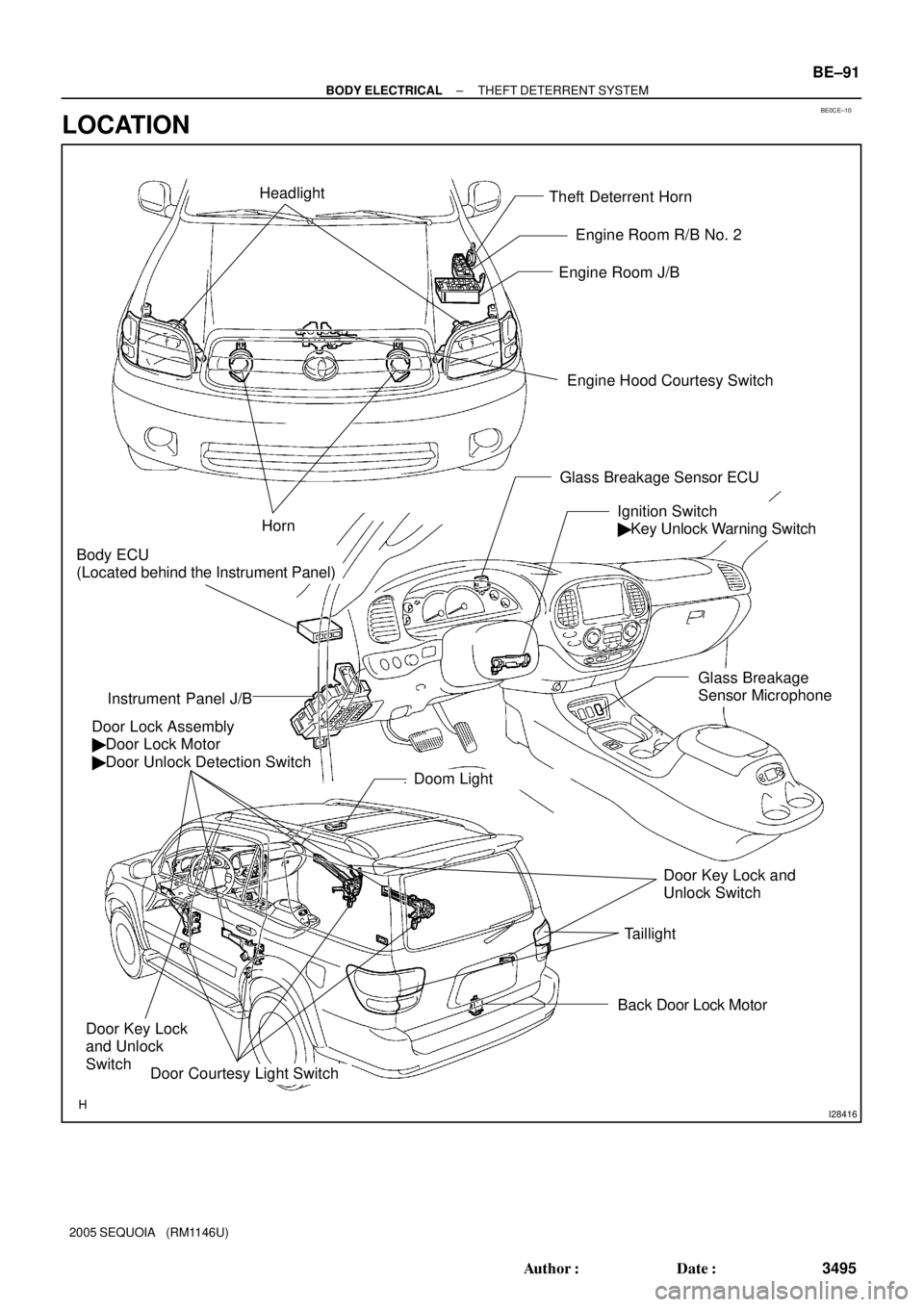
BE0CE±10
I28416
Theft Deterrent Horn
Engine Hood Courtesy Switch Engine Room J/B
Door Lock Assembly
� Door Lock Motor
� Door Unlock Detection Switch
Ignition Switch
� Key Unlock Warning Switch
Instrument Panel J/B
Door Courtesy Light Switch
Horn
Back Door Lock Motor
Door Key Lock
and Unlock
Switch
Door Key Lock and
Unlock Switch Headlight
Doom Light
Taillight
Body ECU
(Located behind the Instrument Panel)
Engine Room R/B No. 2
Glass Breakage Sensor ECU
Glass Breakage
Sensor Microphone
± BODY ELECTRICALTHEFT DETERRENT SYSTEM
BE±91
3495 Author�: Date�:
2005 SEQUOIA (RM1146U)
LOCATION
Page 3505 of 4323

WIRELESS DOOR LOCK CONTROL SYSTEM
ON±VEHICLE INSPECTION
Make the vehicle in the init")
BE2MK±01
± BODY ELECTRICALWIRELESS DOOR LOCK CONTROL SYSTEM
BE±93
3497 Author�: Date�:
2005 SEQUOIA (RM1146U)
WIRELESS DOOR LOCK CONTROL SYSTEM
ON±VEHICLE INSPECTION
Make the vehicle in the initialized condition:
The initialized condition is the condition when the following conditions are satisfied.
(1) Key plate has not been inserted in the ignition key cylinder.
(2) All the doors are closed. (Door warning light is OFF.)
(3) All the doors are locked.
Under the standard operation, when repeating UNLOCK and LOCK switch 3 times or more alternately, check the
UNLOCK±LOCK operation from 3rd time onward.
� Following procedures are standard operation.
(1) Keep about 1 M away to the right direction from the outside handle of a driver's seat.
(2) Face the transmitter toward the vehicle and press one of transmitter switches for about 1 sec.
� As of the security function, even the wireless function is normal, there may be the case that only UNLOCK opera-
tion will not work.
� As of the body customize function, if ºoperation twiceº has been set using hand±held tester, only driver's seat
is unlocked by unlock operation performed once.
Normal
� Operative distance may differ according to
an operator, the way of holding the transmitter
or position.
� Because weak electric wave is used, when
there is strong wave or noise in the used
frequency, operation distance might be
shortened.
No Yes
Only wireless function (Remote control) will not operate.
(If a new transmitter or a transmitter of the same type that works properly with the vehicle is not available.)
Basic function check:
Page 3507 of 4323

No
No
(Not entered in self
diagnostic mode)Is the method to enter into the
diagnostic mode corr")
± BODY ELECTRICALWIRELESS DOOR LOCK CONTROL SYSTEM
BE±95
3499 Author�: Date�:
2005 SEQUOIA (RM1146U)
No
No
(Not entered in self
diagnostic mode)Is the method to enter into the
diagnostic mode correct?
Self diagnostic mode operation check:
Ye s
(Entered in self diagnostic mode)
After the self±diagnostic mode input operation has
been performed, check that the buzzer chirps.
ON
OFF BuzzerIgnition switch OFF
0.13 sec. 0.5 sec.
Is the chirping function of operation
confirmation buzzer normal?
Check door control buzzer.
Check that continuity exists between
connector terminal A3 of MPX body ECU
on the vehicle side and ground by
inserting the key plate into the ignition
key cylinder. Key unlock warning switch inspection:
Ye s Ye s
No
Check key unlock warning switch.
Self diagnostic mode check:
Check that how the buzzer chirps when pressing
each transmitter switch.
ON
OFF Buzzer
0.13 sec.0.5 sec.
(1) Receiver normal wave of LOCK switch.
ON
OFF Buzzer
0.13 sec.
0.25 sec.
(2) Receiver normal wave of UNLOCK switch.
0.5 sec.
ON
OFF Buzzer
(3) Receiver normal wave of luggage door switch.
0.5 sec.0.5 sec.
ON
OFF (4) Incompatibility of the recognition code or out
from synchronization of rolling code.
While receiving
:
While turning the ignition switch ON in the self±
diagnostic mode, the mode returns to normal mode. Buzzer
(1), (2) or (3) are output.(4) is output.
(All buzzer's response
is same.)
Recognition code registration function check:
Check that it is possible to enter into
rewrite mode or add mode.
(Refer to ºWireless door lock receiver and
transmitterº ± ºRecognition code registrationº.)
Wireless door lock operates
normally when recognition code
is registered.
No response from buzzer
Page 3560 of 4323

INSPECTION
1. INSPECT TOWING CONVERTER CIRCUIT
Remove the towing converter wi")
BE2D5±02
I24381
Wire Harness Side: BE±148
± BODY ELECTRICALTRAILER TOWING
3552 Author�: Date�:
2005 SEQUOIA (RM1146U)
INSPECTION
1. INSPECT TOWING CONVERTER CIRCUIT
Remove the towing converter with the connector still connected
and inspect the wire harness side connector from the back side,
as shown in the table below.
Tester connectionConditionSpecified condition
4 ± 6Turn signal switch LEFT or hazard warning switch ON10 ± 14 V e 0 V
4 ± 6Turn signal switch LEFT and stop light switch ON (Brake pedal depressed)10 ± 14 V e 0 V
4 ± 6Turn signal switch OFF, hazard warning switch OFF and stop light switch OFF
(Brake pedal released)0 V
4 ± 6Stop light switch ON (Brake pedal depressed)10 ± 14 V
6 ± 9Turn signal switch LEFT or hazard warning switch ON10 ± 14 V e 0 V
6 ± 9Turn signal switch OFF or RIGHT and hazard warning switch OFF0 V
6 ± Body groundAlwaysContinuity
2 ± 6Turn signal switch RIGHT or hazard warning switch ON10 ± 14 V e 0 V
2 ± 6Turn signal switch RIGHT and stop light switch ON (Brake pedal depressed)10 ± 14 V e 0 V
26Turn signal switch OFF, and hazard warning switch OFF and stop light switch OFF0V2 ± 6Turn signal switch OFF, and hazard warning switch OFF and sto light switch OFF
(Brake pedal released)0 V
2 ± 6Stop light switch ON (Brake pedal depressed)10 ± 14 V e 0 V
1 ± 6Always10 ± 14 V
6 ± 8Stop light switch ON (Brake pedal depressed)10 ± 14 V
6 ± 8Stop light switch OFF (Brake pedal released)0 V
3 ± 6Turn signal switch RIGHT or hazard warning switch ON10 ± 14 V e 0 V
3 ± 6Turn signal switch OFF or LEFT and hazard warning switch OFF0 V
If the circuit is not as specified, inspect the circuit connected to
other parts.
Page 3851 of 4323

ii
2005 SEQUOIA from Aug. 04 Prod. (OM34424U)
Important information about this manual
Safety and vehicle damage warnings
Throughout this manual, you will see safety and vehicl")
05_SEQUOIA_U (L/O 0408)
ii
2005 SEQUOIA from Aug. '04 Prod. (OM34424U)
Important information about this manual
Safety and vehicle damage warnings
Throughout this manual, you will see safety and vehicle dam-
age warnings. You must follow these warnings carefully to
avoid possible injury or damage.
The types of warnings, what they look like, and how they are
used in this manual are explained as follows:
CAUTION
This is a warning against anything which may cause
injury to people if the warning is ignored. You are
informed about what you must or must not do in
order to reduce the risk of injury to yourself and
others.
NOTICE
This is a warning against anything which may cause
damage to the vehicle or its equipment if the warning
is ignored. You are informed about what you must or
must not do in order to avoid or reduce the risk of
damage to your vehicle and its equipment.
Safety symbol
When you see the safety symbol
shown above, it means: ªDo not...º;
ªDo not do thisº; or ªDo not let this
happenº.