Page 3024 of 4323
SA2CV±01
F16822
F16822
SA±20
± SUSPENSION AND AXLETIRE PRESSURE MONITOR ECU
3016 Author�: Date�:
2005 SEQUOIA (RM1146U)
REPLACEMENT
1. DISCONNECT CABLE FROM NEGATIVE BATTERY
TERMINAL
2. REMOVE INTEGRATION CONTROL PANEL
(See page BO±89)
3. REMOVE GLOVE COMPARTMENT
(See page BO±89)
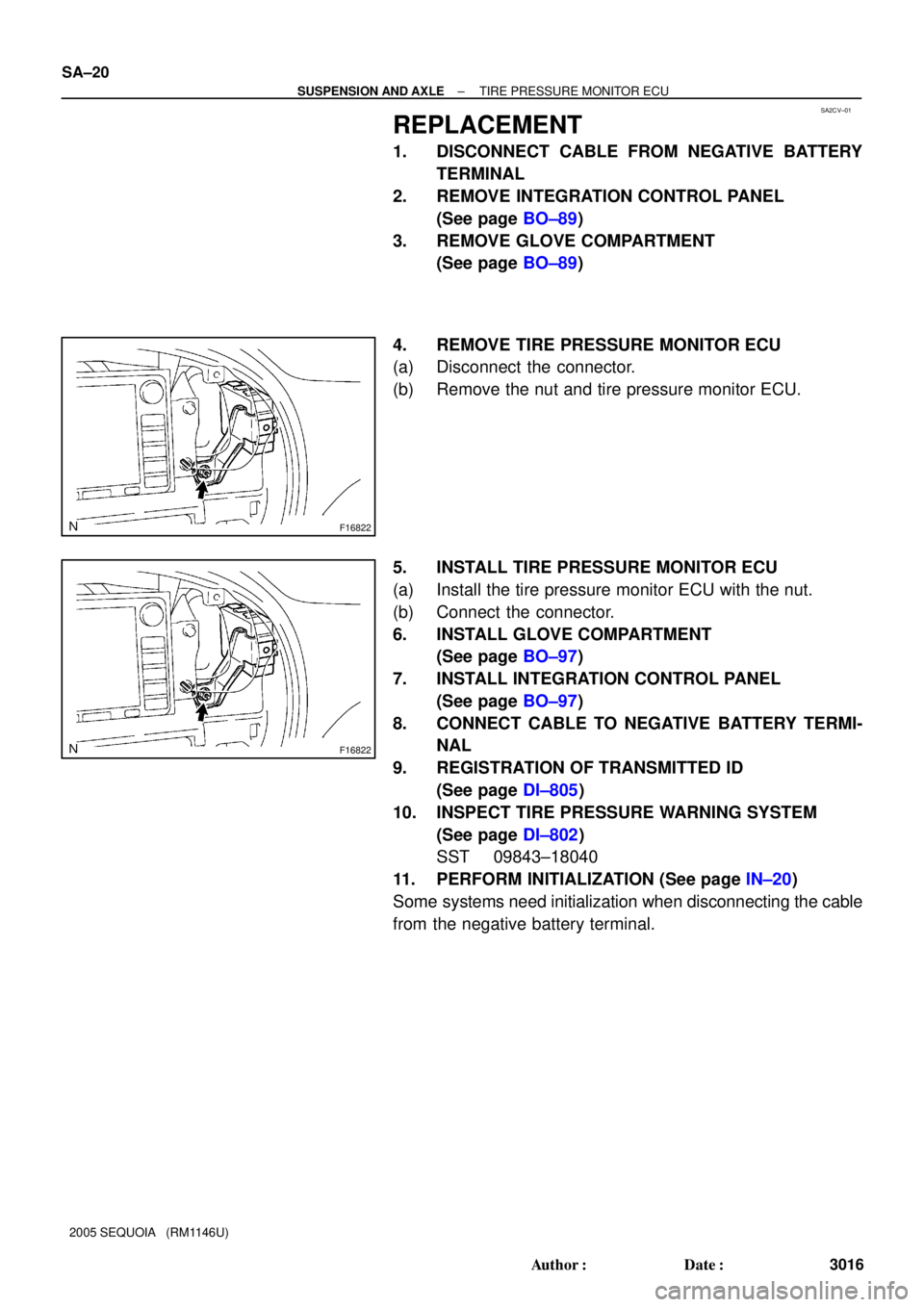
4. REMOVE TIRE PRESSURE MONITOR ECU
(a) Disconnect the connector.
(b) Remove the nut and tire pressure monitor ECU.
5. INSTALL TIRE PRESSURE MONITOR ECU
(a) Install the tire pressure monitor ECU with the nut.
(b) Connect the connector.
6. INSTALL GLOVE COMPARTMENT
(See page BO±97)
7. INSTALL INTEGRATION CONTROL PANEL
(See page BO±97)
8. CONNECT CABLE TO NEGATIVE BATTERY TERMI-
NAL
9. REGISTRATION OF TRANSMITTED ID
(See page DI±805)
10. INSPECT TIRE PRESSURE WARNING SYSTEM
(See page DI±802)
SST 09843±18040
11. PERFORM INITIALIZATION (See page IN±20)
Some systems need initialization when disconnecting the cable
from the negative battery terminal.
Page 3190 of 4323
BR10E±04
F16310
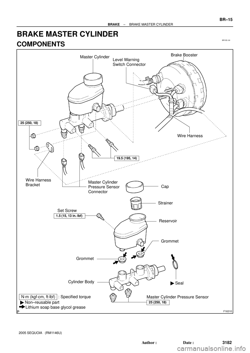
Master Cylinder
Level Warning
Switch ConnectorBrake Booster
Cap
Strainer
Reservoir Set Screw
Grommet
Cylinder Body
N´m (kgf´cm, ft´lbf) : Specified torque
� Non±reusable part
Lithium soap base glycol greaseWire Harness
BracketMaster Cylinder
Pressure Sensor
Connector
Master Cylinder Pressure Sensor� Seal
25 (250, 18)
25 (250, 18)
19.5 (195, 14)
Wire Harness
1.5 (15, 13 in.´lbf)
Grommet
± BRAKEBRAKE MASTER CYLINDER
BR±15
3182 Author�: Date�:
2005 SEQUOIA (RM1146U)
BRAKE MASTER CYLINDER
COMPONENTS
Page 3191 of 4323
BR08U±05
F16312
F16313
BR±16
± BRAKEBRAKE MASTER CYLINDER
3183 Author�: Date�:
2005 SEQUOIA (RM1146U)
REMOVAL
1. DRAW OUT FLUID WITH SYRINGE
NOTICE:
Wash the brake fluid off immediately if it comes into con-
tact with any painted surface.
2. DISCONNECT LEVEL WARNING SWITCH CONNEC-
TOR
3. DISCONNECT 2 MASTER CYLINDER PRESSURE
SENSOR CONNECTORS
4. DISCONNECT WIRE HARNESS
Using a clip remover, disconnect the wire harness from the wire
harness bracket.
5. DISCONNECT BRAKE LINES
Using SST, disconnect the 2 brake lines from the master cylin-
der.
SST 09023±38201
Torque: 19.5 N´m (195 kgf´cm, 14 ft´lbf)
6. REMOVE MASTER CYLINDER
(a) Remove the 2 nuts and wire harness bracket.
Torque: 25 N´m (250 kgf´cm, 18 ft´lbf)
(b) Pull out the master cylinder from the brake booster.
Page 3196 of 4323
BR10G±04
F16311
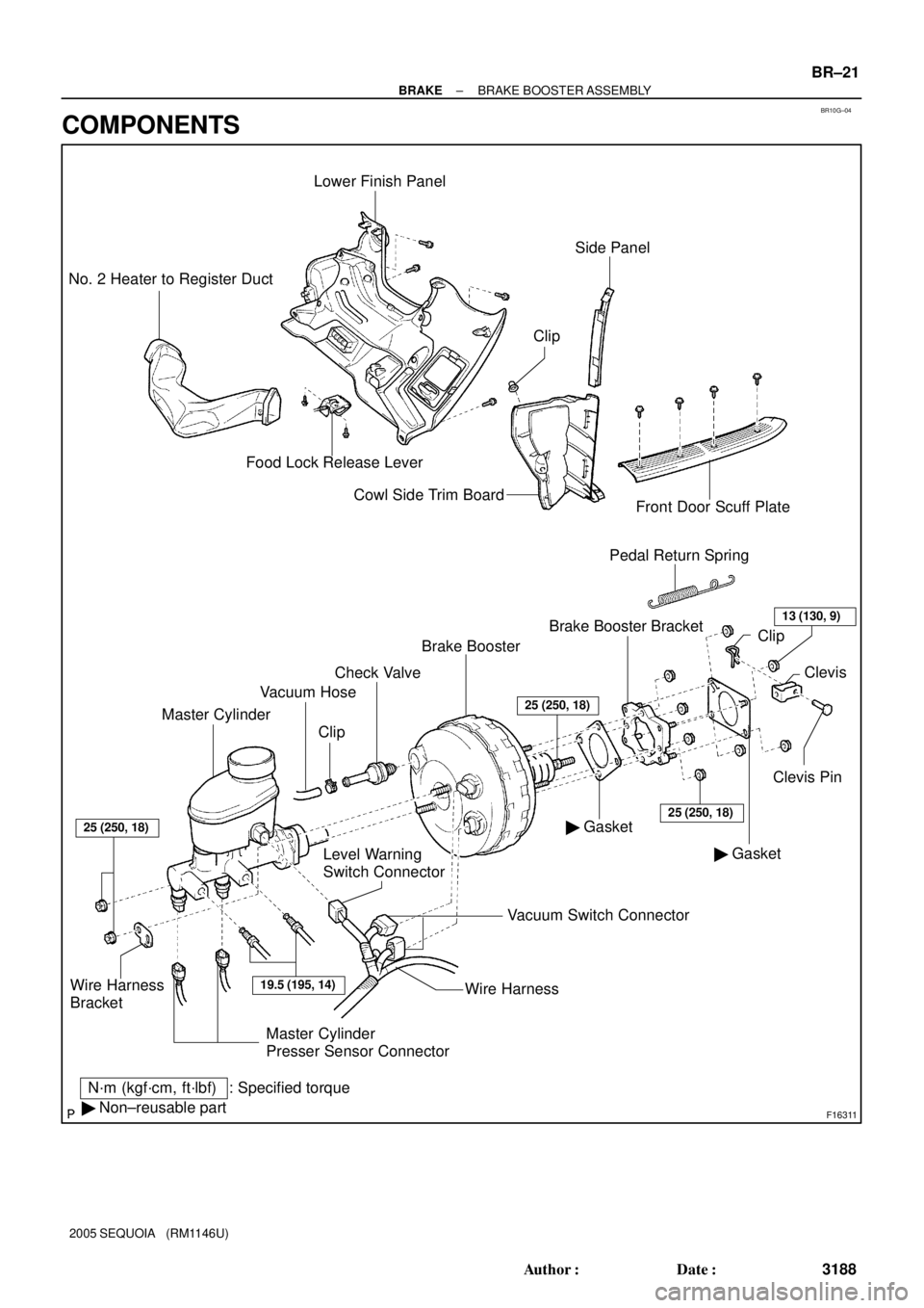
Master CylinderVacuum Hose
Level Warning
Switch ConnectorBrake Booster
� GasketClevis Pin Brake Booster Bracket Clip
: Specified torque
N´m (kgf´cm, ft´lbf)
� Non±reusable partPedal Return Spring
Wire Harness
Bracket
Lower Finish Panel
Food Lock Release Lever No. 2 Heater to Register Duct
Cowl Side Trim Board
Front Door Scuff Plate
� GasketClevis
Vacuum Switch Connector
19.5 (195, 14)
25 (250, 18)
25 (250, 18)
ClipCheck Valve
25 (250, 18)
Side Panel
Wire Harness
13 (130, 9)
Clip
Master Cylinder
Presser Sensor Connector
± BRAKEBRAKE BOOSTER ASSEMBLY
BR±21
3188 Author�: Date�:
2005 SEQUOIA (RM1146U)
COMPONENTS
Page 3248 of 4323
F13256
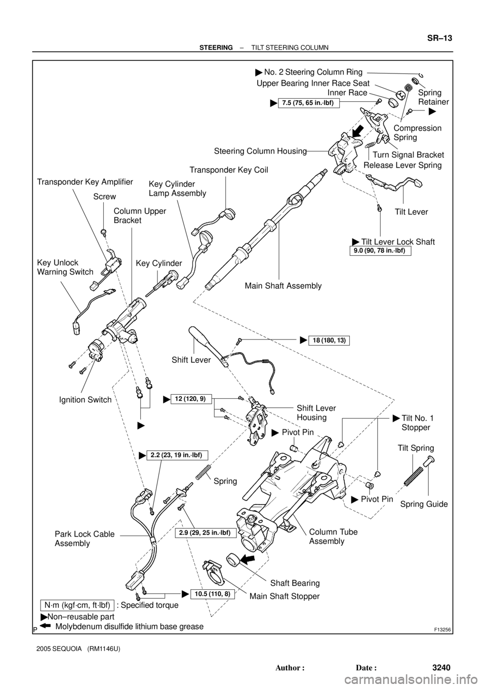
�Non±reusable part
Molybdenum disulfide lithium base grease
: Specified torqueN´m (kgf´cm, ft´lbf)Column Upper
Bracket
Key Cylinder Key Unlock
Warning Switch
Ignition Switch
10.5 (110, 8)�Column Tube
Assembly
2.2 (23, 19 in.´lbf)�
Spring Guide
�
Tilt Spring Main Shaft Assembly Steering Column Housing
Tilt Lever Release Lever SpringTurn Signal Bracket�
Compression
SpringSpring
Retainer Upper Bearing Inner Race Seat
Inner Race
�12 (120, 9)
Pivot Pin
Spring
Park Lock Cable
Assembly
Shaft Bearing
Main Shaft Stopper
Pivot Pin Shift Lever
Housing
18 (180, 13)�� �
Shift Lever
No. 2 Steering Column Ring�
Tilt Lever Lock Shaft9.0 (90, 78 in.´lbf)
�
��
7.5 (75, 65 in.´lbf)
2.9 (29, 25 in.´lbf)
Transponder Key Coil
Key Cylinder
Lamp Assembly
Screw
Transponder Key Amplifier
Tilt No. 1
Stopper
± STEERINGTILT STEERING COLUMN
SR±13
3240 Author�: Date�:
2005 SEQUOIA (RM1146U)
Page 3254 of 4323

INSPECTION
1. INSPECT STEERING LOCK OPERATION
Check that the steering lock mechanism")
SR0V2±05
F13613
F13618
R11908
± STEERINGTILT STEERING COLUMN
SR±19
3246 Author�: Date�:
2005 SEQUOIA (RM1146U)
INSPECTION
1. INSPECT STEERING LOCK OPERATION
Check that the steering lock mechanism operates properly.
2. IF NECESSARY, REPLACE KEY CYLINDER
(a) Turn the ignition key to the ACC position.
(b) Push down the stop pin with a screwdriver, and pull out
the cylinder.
(c) Install a new cylinder.
HINT:
Make sure that the key is in the ACC position.
3. INSPECT IGNITION SWITCH (See page BE±24)
4. IF NECESSARY, REPLACE IGNITION SWITCH
(a) Remove the 2 screws and ignition switch.
(b) Install a new ignition switch with the 2 screws.
5. INSPECT KEY UNLOCK WARNING SWITCH
(See page BE±24)
6. IF NECESSARY, REPLACE KEY UNLOCK WARNING
SWITCH
(a) Slide out the key unlock warning switch.
(b) Install a new key unlock warning switch.
7. INSPECT TRANSPONDER KEY COIL
(See page BE±143)
8. IF NECESSARY, REPLACE TRANSPONDER KEY
COIL
9. IF NECESSARY, REPLACE TRANSPONDER KEY AM-
PLIFIER
(a) Remove the screw and transponder key amplifier.
(b) Install a new transponder key amplifier with the screw.
10. INSPECT BEARING
(a) Check that the bearing rotates smoothly without abnor-
mal noise.
If it does not rotate smoothly or abnormal noise occurs, replace
the column housing.
(b) Coat the bearing with molybdenum disulfide lithium base
grease.
Page 3293 of 4323

�If the steering wheel pad, front passenger airbag assembly, side airbag assembly, curtain
shield airbag")
RS±2
± SUPPLEMENTAL RESTRAINT SYSTEMSRS AIRBAG
3285 Author�: Date�:
2005 SEQUOIA (RM1146U)
�If the steering wheel pad, front passenger airbag assembly, side airbag assembly, curtain
shield airbag assembly, airbag sensor assembly, front airbag sensor, side airbag sensor as-
sembly, curtain shield airbag sensor assembly, seat position sensor assembly or occupant
classification ECU has been dropped, or if there are any cracks, dents or other defects in the
case, bracket or connector, replace it with a new one.
�Use a volt/ohmmeter with high impedance (10 kW/V minimum) for troubleshooting the electrical
circuits.
�Information labels are attached to the periphery of the SRS components. Follow the instruc-
tions in the caution.
�After work on the SRS is completed, perform the SRS warning light check (see page DI±1137).
�When the negative (±) terminal cable is disconnected from the battery, the memory will be
cleared. Because of this, be sure to make a record of the contents memorized in each system
before starting work. When work is finished, adjust each system as it was before. Never use
a back±up power supply from outside the vehicle to avoid erasing the memory in any system.
Page 3295 of 4323

4. SIDE AIRBAG ASSEMBLY
The inflator and bag of the SRS are stored in")
H17489
H23919
H16185
H23920
H16187
RS±4
± SUPPLEMENTAL RESTRAINT SYSTEMSRS AIRBAG
3287 Author�: Date�:
2005 SEQUOIA (RM1146U)
4. SIDE AIRBAG ASSEMBLY
The inflator and bag of the SRS are stored in the side airbag as-
sembly and cannot be disassembled. The inflator contains a
squib, igniter charge and gas generator, etc., and inflates the
bag when instructed by the airbag sensor assembly. The side
airbag assembly cannot be disassembled.
5. CURTAIN SHIELD AIRBAG ASSEMBLY
The inflator and bag of the SRS are stored in the curtain shield
airbag assembly and cannot be disassembled. The inflator con-
tains a squib, igniter charge, gas generator, etc., and inflates
the bag when instructed by the airbag sensor assembly. The
curtain shield airbag assembly cannot be disassembled.
6. SEAT BELT PRETENSIONER
The front seat outer belt has the seat belt pretensioner system.
The pretensioner operates in the event of a frontal collision. The
seat belt pretensioner cannot be disassembled.
7. SRS WARNING LIGHT
The SRS warning light is located on the combination meter. It
comes on to alert the driver of trouble in the system when a mal-
function is detected in the airbag sensor assembly. In normal
operation conditions when the ignition switch is turned to the
ON position, the light comes on for approximately 6 seconds
and then goes off.
8. AIRBAG SENSOR ASSEMBLY
The airbag sensor assembly is mounted on the floor inside the
lower center finish panel. The airbag sensor assembly consists
of an airbag sensor, safing sensor, diagnosis circuit, ignition
control, drive circuit, etc. It receives signals from the airbag sen-
sor, front airbag sensor, side and curtain shield airbag sensor
and curtain shield airbag sensor, and judges whether the SRS
must be activated or not. The airbag sensor assembly cannot
be disassembled.