Page 3422 of 4323
 Some of the system does not operate.
(Taillight does not come on.)
1. TAIL Fuse
2. TAILLIGHT Relay
3. Light Contr")
BE±10
± BODY ELECTRICALTROUBLESHOOTING
3414 Author�: Date�:
2005 SEQUOIA (RM1146U) Some of the system does not operate.
(Taillight does not come on.)
1. TAIL Fuse
2. TAILLIGHT Relay
3. Light Control Switch
4. Wire Harness
5. Body ECUBE±14
BE±27
BE±27
±
±
Some of the system do not operate.
(Theft deterrent horn or vehicle horn does not sound.)
1. HORN Fuse
2. SECURITY HORN Fuse
3. HORN Relay Circuit
4. Theft Deterrent Horn Circuit
5. Horn
6. Body ECUBE±14
BE±14
BE±145
BE±92
BE±145
±
While the warning is given, the system cannot be canceled by
unlocking the door with a key or transmitter.
1. Door Key Lock and Unlock Switch Circuit (Driver Door
ECU)
Door Key Lock and Unlock Switch Circuit (Passenger
Door ECU)
Door Key Lock and Unlock Switch Circuit (Back Door
ECU)
2. Body ECUDI±1794
DI±1832
DI±1882
±
*1: w/ Glass breakage sensor
WIRELESS DOOR LOCK CONTROL SYSTEM
This system uses the multiplex communication system, so check diagnosis system of the multiplex commu-
nication system before you proceed with troubleshooting.
HINT:
�Troubleshooting of the wireless door lock control system is based on the premise that the door lock
control system operates normally. Accordingly, before troubleshooting the wireless door lock control
system, first make certain that the door lock control system operates normally.
�If the trouble still reappears even though there are no abnormalities in any of the other circuits, check
and replace the Wireless Door Lock Control Receiver as the last step.
SymptomSuspect AreaSee page
All functions of wireless door lock control system do not operate.
1. Transmitter
2. Wireless Door Lock Control Receiver Circuit
3. Body ECUBE±98
DI±1737
±
Wireless door lock operates, but the buzzer does not sound.
(The buzzer does not sound when the customize function prohib-
its.)1. Wireless Door Lock Buzzer Circuit
2. Body ECUDI±1741
±
POWER SEAT CONTROL SYSTEM (w/o Driving Position Memory)
SymptomSuspect AreaSee page
Both Driver and Passenger Power seats do not operate.1. PWR SEAT Fuse
2. Wire HarnessBE±14
±
Driver's seat does not operate.1. Power Seat Switch (D)
2. Wire HarnessBE±109
±
Passenger's seat does not operate.1. Power Seat Switch (P)
2. Wire HarnessBE±109
±
ºSlide operationº does not operate.
1. Power Seat Switch (D, P)
2. Slide Motor (D, P)
3. Wire HarnessBE±109
BE±109
±
ºFront Vertical Operationº does not operate.
1. Power Seat Switch (D)
2. Front Vertical Motor (D)
3. Wire HarnessBE±109
BE±109
±
ºLifter Operationº does not operate.
1. Power Seat Switch (D)
2. Lifter Motor (D)
3. Wire HarnessBE±109
BE±109
±
Page 3435 of 4323
BE0OP±20
I28401
Ignition SwitchKey Unlock Warning SwitchInstrument Panel J/B
� IG2 Fuse
± BODY ELECTRICALIGNITION SWITCH AND KEY UNLOCK WARNING
SWITCHBE±23
3427 Author�: Date�:
2005 SEQUOIA (RM1146U)
IGNITION SWITCH AND KEY UNLOCK WARNING SWITCH
LOCATION
Page 3436 of 4323
BE25S±04
I08467
LOCKACC
ON
START
N20125
1 2 OFF
ON BE±24
± BODY ELECTRICALIGNITION SWITCH AND KEY UNLOCK WARNING
SWITCH
3428 Author�: Date�:
2005 SEQUOIA (RM1146U)
INSPECTION
1. INSPECT IGNITION SWITCH CONTINUITY
Switch positionTester connectionSpecified condition
LOCK±No continuity
ACC1 ± 3Continuity
ON1 ± 2 ± 3
5 ± 6Continuity
START1 ± 2
4 ± 5 ± 6Continuity
If continuity is not as specified, replace the switch.
2. INSPECT KEY UNLOCK WARNING SWITCH CONTI-
NUITY
Switch positionTester connectionSpecified condition
OFF (Key removed)±No continuity
ON (Key set)1 ± 2Continuity
If continuity is not as specified, replace the switch.
Page 3447 of 4323
BE033±09
I28404
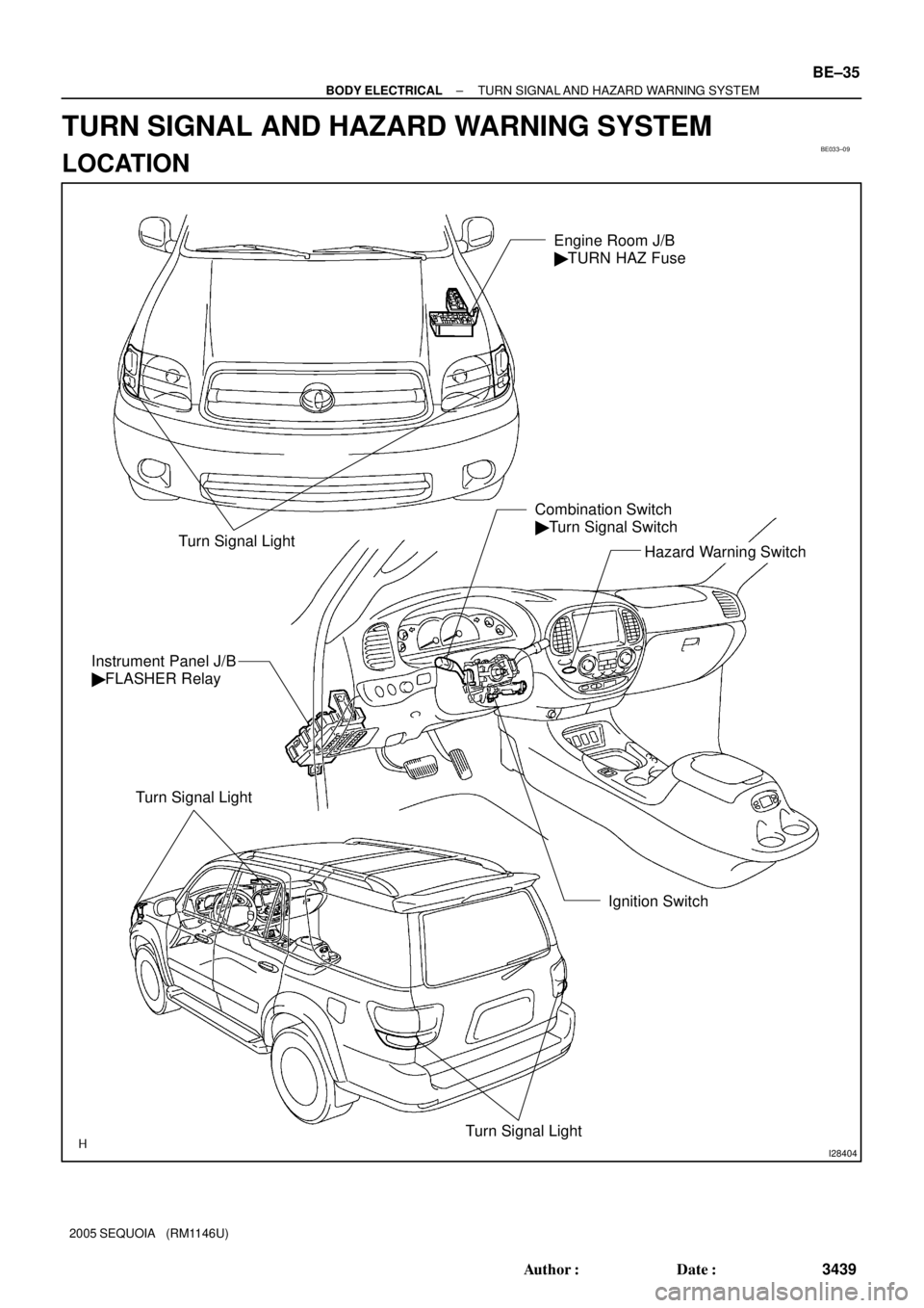
Turn Signal LightHazard Warning Switch Combination Switch
� Turn Signal Switch
Ignition Switch Instrument Panel J/B
� FLASHER Relay
Turn Signal Light
Turn Signal Light
Engine Room J/B
� TURN HAZ Fuse
± BODY ELECTRICALTURN SIGNAL AND HAZARD WARNING SYSTEM
BE±35
3439 Author�: Date�:
2005 SEQUOIA (RM1146U)
TURN SIGNAL AND HAZARD WARNING SYSTEM
LOCATION
Page 3448 of 4323

BE2DD±03
I12796
Right Turn
2 4 5 7 8
9 631
10 11 12 13 14 15 16 17
Left Turn
I04046
Wire Harness Side: BE±36
± BODY ELECTRICALTURN SIGNAL AND HAZARD WARNING SYSTEM
3440 Author�: Date�:
2005 SEQUOIA (RM1146U)
INSPECTION
1. INSPECT TURN SIGNAL SWITCH CONTINUITY
Switch positionTester connectionSpecified condition
Left turn1 ± 2Continuity
Neutral±No continuity
Right turn2 ± 3Continuity
If continuity is not as specified, replace the switch.
2. Connector disconnected:
INSPECT TURN SIGNAL FLASHER CIRCUIT
Disconnect the connector from the turn signal flasher and in-
spect the connector on the wire harness side as shown in the
table below.
Tester connectionConditionSpecified condition
1 ± GroundIgnition switch LOCK or ACCNo voltage
1 ± GroundIgnition switch ONBattery positive voltage
2 ± GroundAlwaysContinuity
3 ± GroundAlwaysContinuity
4 ± GroundAlwaysBattery positive voltage
5 ± GroundTurn signal switch RIGHT or OFFNo Continuity
5 ± GroundTurn signal switch LEFTContinuity
6 ± GroundTurn signal switch LEFT or OFFNo Continuity
6 ± GroundTurn signal switch RIGHTContinuity
7 ± GroundAlwaysContinuity
8 ± GroundHazard warning switch OFFNo Continuity
8 ± GroundHazard warning switch ONContinuity
If the circuit is as specified, perform the inspection on the next
step.
If the circuit is not as specified, inspect the circuit connected to
other parts.
Page 3449 of 4323
I24334
Turn Signal Flasher Relay
Connector Front View:
I28728
10
19
± BODY ELECTRICALTURN SIGNAL AND HAZARD WARNING SYSTEM
BE±37
3441 Author�: Date�:
2005 SEQUOIA (RM1146U)
3. Connector connected:
INSPECT TURN SIGNAL FLASHER RELAY OPERA-
TION
Connect the wire harness side connector to the turn signal
flasher and inspect the connector from the back side, as shown.
Tester connectionConditionSpecified condition
2 ± GroundTurn signal switch RIGHTBattery positive voltage e 0 V
3 ± GroundTurn signal switch LEFTBattery positive voltage e 0 V
If operation is not as specified, replace the relay.
4. INSPECT HAZARD WARNING SWITCH CONTINUITY
(a) Remove the center cluster finish panel.
(b) Disconnect the connector from the integrated center clus-
ter.
(c) Check that continuity exists between terminals 19 and 10
with the switch ON.
(d) Check that no continuity exists between terminals 19 and
10 with the switch OFF.
If continuity is not as specified, replace the switch.
Page 3465 of 4323
BE17A±06
I28425
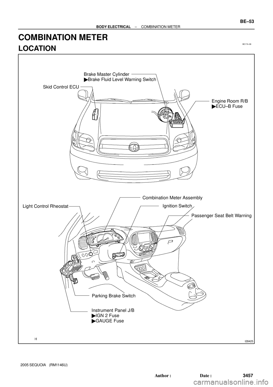
Brake Master Cylinder
� Brake Fluid Level Warning Switch
Engine Room R/B
� ECU±B Fuse
Light Control Rheostat
Combination Meter Assembly
Instrument Panel J/B
� IGN 2 Fuse
� GAUGE Fuse
Parking Brake SwitchIgnition Switch
Passenger Seat Belt Warning
Skid Control ECU
± BODY ELECTRICALCOMBINATION METER
BE±53
3457 Author�: Date�:
2005 SEQUOIA (RM1146U)
COMBINATION METER
LOCATION
Page 3468 of 4323
(3.4W) Fuel Gauge
Z05730
Warning Light
Ignition
Switch
Battery
1
23
45
Wire
Harness Side:
I28772
I01278
BE±56
± BODY ELECTRICALCOMBINATION METER
346")
I21530
Ignition
Switch
Battery(Wire Harness Side)(3.4W) Fuel Gauge
Z05730
Warning Light
Ignition
Switch
Battery
1
23
45
Wire
Harness Side:
I28772
I01278
BE±56
± BODY ELECTRICALCOMBINATION METER
3460 Author�: Date�:
2005 SEQUOIA (RM1146U)
(c) Connect terminals 2 and 3 on the wire harness side con-
nector through a 3.4 watts test bulb.
(d) Turn the ignition switch ON, check that the bulb comes on
and the receiver gauge needle moves towards the full
side.
HINT:
Because of silicon oil in the gauge, it will take a short time for
the needle to stabilize.
If operation is not as specified, inspect the receiver gauge resis-
tance.
4. INSPECT FUEL LEVEL WARNING LIGHT OPERATION
(a) Disconnect the connector from the sender gauge.
(b) Connect terminals 2 and 3 on the wire harness side con-
nector.
(c) Turn the ignition switch ON and check that the warning
light comes on.
If the warning light does not come on, test the bulb or inspect
the wire harness.
5. INSPECT ENGINE COOLANT TEMPERATURE SEND-
ER GAUGE RESISTANCE
(a) Disconnect the engine coolant temperature sender
gauge.
(b) Measure the resistance between terminals 1 and 2 of the
connector according to the value(s) in the table below.
Temperature °C (°F)Resistance (W)
±20 (±4)13,840 to 16,330
20 (68)2,320 to 2,590
80 (176)310 to 326
110 (230)139.9 to 143.5
If resistance value is not as specified, replace the engine cool-
ant sender gauge.
6. INSPECT OIL PRESSURE SENDER OPERATION
(a) Disconnect the connector from the oil pressure sender.
(b) Check that no continuity exists between terminal and
ground with the engine stopped.
(c) Check that continuity exists between terminal and ground
with the engine running.
HINT:
Oil pressure should be over 24.5 kPa (0.25 kgf/cm
2, 3.55 psi).
If operation is not as specified, replace the oil pressure sender.