Page 2546 of 4323

I29010
Pressure switch:
A4
DI±2344
± DIAGNOSTICSAIR CONDITIONING SYSTEM
2538 Author�: Date�:
2005 SEQUOIA (RM1146U)
INSPECTION PROCEDURE
1 Check refrigerant pressure.
(a) Set the manifold gauge.
(b) Read the manifold gauge pressure when these conditions are established.
Test conditions:
�Temperature at the air inlet with the switch set at RECIRC is 30 to 35°C (86 to 95°F)
�Engine running at 1,500 rpm
�Blower speed control switch at ºHIº position
�Temperature control dial at ºCOOLº position
�Air conditioning switch ON
�Fully open doors
Standard:
Pressure on high pressure side:
1.37 to 1.57 MPa (13.9 to 16.0 kgfVcm
2, 198 to 228 psi)
HINT:
If the refrigerant pressure is below 196 KPa (2.0 kgfVcm
2, 28 psi), the refrigerant amount the air conditioning
cycle may have decreased significantly for reasons such as a gas leakage.
NG Check air conditioning cycle
(See page AC±3).
OK
2 Check air conditioning operation.
(a) Disconnect the pressure switch connector.
(b) Connect terminals 1 and 4 of the connector of the pres-
sure switch on the vehicle wire harness side using a ser-
vice wire.
(c) Start the engine.
(d) Turn the air conditioning switch is on and check that the
magnet clutch is turned on.
(e) Check that the magnet clutch is turned off when discon-
necting terminals 1 and 4 (that are connected in the prior
step).
OK:
Terminals 1 and 4 connected: magnet clutch is on
Terminals 1 and 4 disconnected: magnet clutch is off
NG Go to step 3.
OK
Page 2552 of 4323
I28847
SG±TPI TPII20 Integration Control and Panel:
DI±2350
± DIAGNOSTICSAIR CONDITIONING SYSTEM
2544 Author�: Date�:
2005 SEQUOIA (RM1146U)
INSPECTION PROCEDURE
1 Check voltage between terminals TPI and SG±TPI of integration control and pan-
el.
PREPARATION:
Remove the integration control and panel with connectors still
connected.
CHECK:
(a) Turn the ignition switch to ON.
(b) Press the REC/FRS switch to change air inlet between
fresh and recirculation air, and measure the voltage be-
tween terminals TPI and SG±TPI of the integration con-
trol and panel when the air inlet damper control servomo-
tor operates.
OK:
FRS±REC SwitchVoltage
REC3.5 to 4.5 V
FRS0.5 to 1.5 V
HINT:
As the air inlet damper control servomotor is moved from the
REC side to the FRS side, the voltage decreases.
NG Go to step 2.
OK
Proceed to next circuit inspection shown in problem symptoms table (See page DI±2304). How-
ever, if DTC 32 or 42 is displayed, replace integration control and panel.
Page 2628 of 4323
A23337
12
345
6
7
811
12 13
14
15
1617
18 2122
910 1920
A23338
Service Bolt
A23339
Approx.
10°
A23340
1 2
21
22
19 20
7
8 11
12
13
14
15
16
3
4 17
18
5
6 9
10
± ENGINE MECHANICALCYLINDER HEAD
EM±41
2620 Author�: Date�:
2005 SEQUOIA (RM1146U)
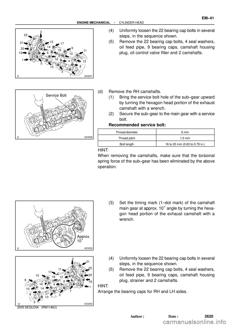
(4) Uniformly loosen the 22 bearing cap bolts in several
steps, in the sequence shown.
(5) Remove the 22 bearing cap bolts, 4 seal washers,
oil feed pipe, 9 bearing caps, camshaft housing
plug, oil control valve filter and 2 camshafts.
(d) Remove the RH camshafts.
(1) Bring the service bolt hole of the sub±gear upward
by turning the hexagon head portion of the exhaust
camshaft with a wrench.
(2) Secure the sub±gear to the main gear with a service
bolt.
Recommended service bolt:
Thread diameter6 mm
Thread pitch1.0 mm
Bolt length16 to 20 mm (0.63 to 0.79 in.)
HINT:
When removing the camshafts, make sure that the torsional
spring force of the sub±gear has been eliminated by the above
operation.
(3) Set the timing mark (1±dot mark) of the camshaft
main gear at approx. 10° angle by turning the hexa-
gon head portion of the exhaust camshaft with a
wrench.
(4) Uniformly loosen the 22 bearing cap bolts in several
steps, in the sequence shown.
(5) Remove the 22 bearing cap bolts, 4 seal washers,
oil feed pipe, 9 bearing caps, camshaft housing
plug, strainer and 2 camshafts.
HINT:
Arrange the bearing caps for RH and LH sides.
Page 2630 of 4323
A233435 mm Hexagon Wrench SST
B02642B02644A04229
RH Bank
LH Bank1
23 4
5 6
7
89
10
3
1 5
7 10
9 8
6 2
4
B02643
B02645A04230
Portion A
Portion A RH Bank
LH Bank
± ENGINE MECHANICALCYLINDER HEAD
EM±43
2622 Author�: Date�:
2005 SEQUOIA (RM1146U)
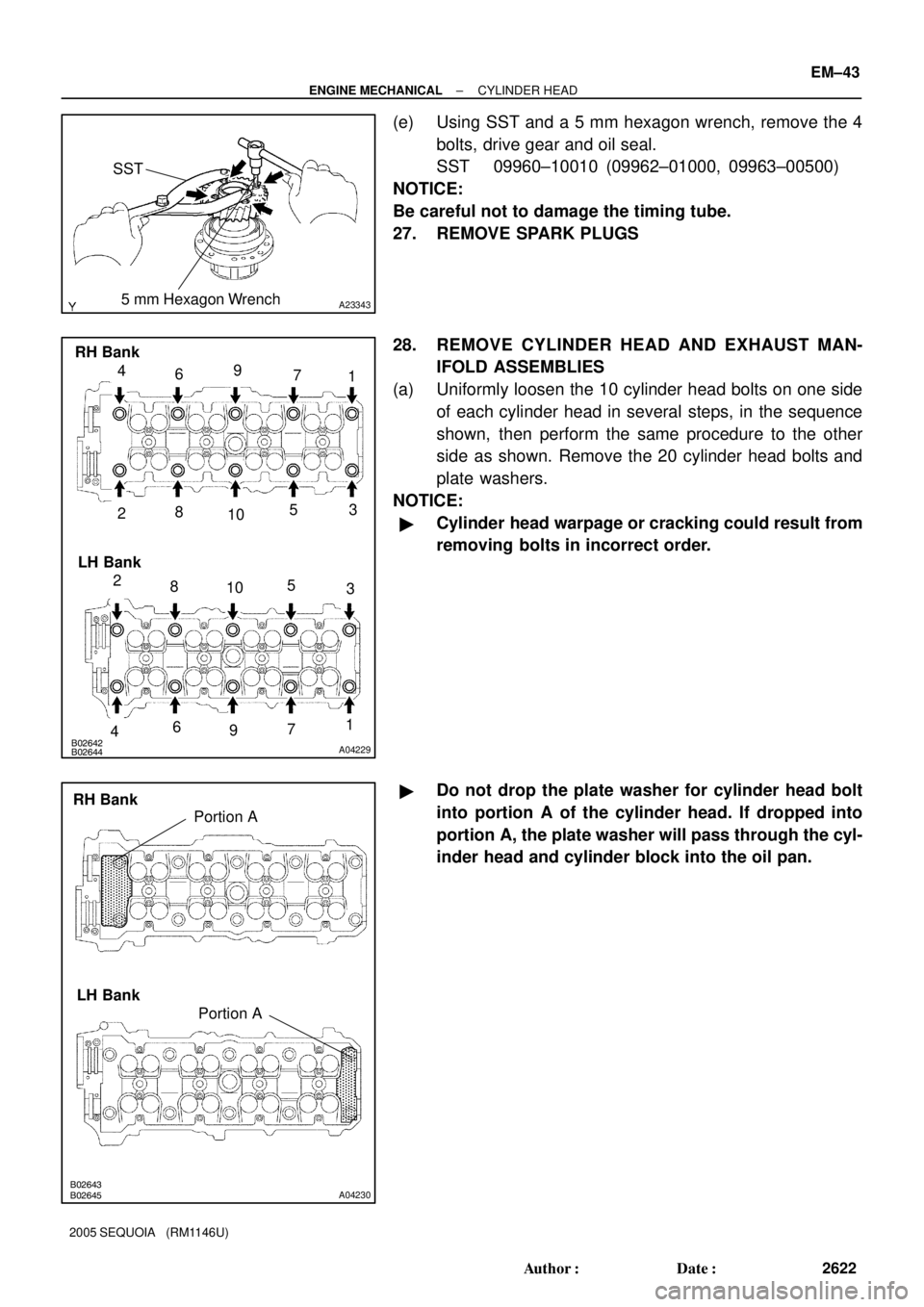
(e) Using SST and a 5 mm hexagon wrench, remove the 4
bolts, drive gear and oil seal.
SST 09960±10010 (09962±01000, 09963±00500)
NOTICE:
Be careful not to damage the timing tube.
27. REMOVE SPARK PLUGS
28. REMOVE CYLINDER HEAD AND EXHAUST MAN-
IFOLD ASSEMBLIES
(a) Uniformly loosen the 10 cylinder head bolts on one side
of each cylinder head in several steps, in the sequence
shown, then perform the same procedure to the other
side as shown. Remove the 20 cylinder head bolts and
plate washers.
NOTICE:
�Cylinder head warpage or cracking could result from
removing bolts in incorrect order.
�Do not drop the plate washer for cylinder head bolt
into portion A of the cylinder head. If dropped into
portion A, the plate washer will pass through the cyl-
inder head and cylinder block into the oil pan.
Page 2648 of 4323
A23352
A05563
RH Cylinder Head
LH Cylinder Head 2UR
2UL
B02642B02644A04229
RH Bank
LH Bank
1 79
4
6
5
3
10
8
27
96
5
3
10
8
2
1
4
± ENGINE MECHANICALCYLINDER HEAD
EM±61
2640 Author�: Date�:
2005 SEQUOIA (RM1146U)
(c) Install the heat insulator with the 4 bolts.
Torque: 7.5 N´m (76 kgf´cm, 66 in.´lbf)
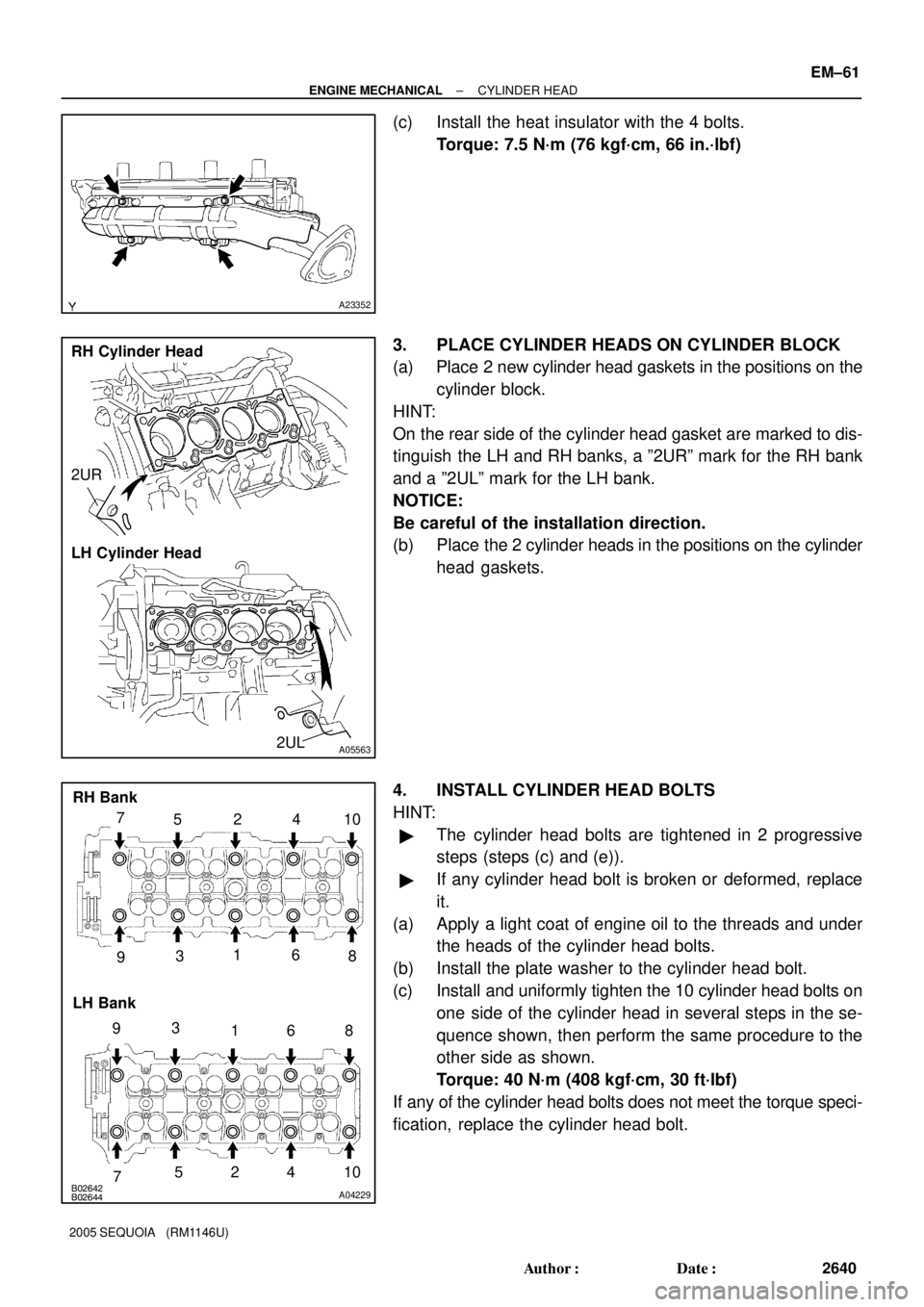
3. PLACE CYLINDER HEADS ON CYLINDER BLOCK
(a) Place 2 new cylinder head gaskets in the positions on the
cylinder block.
HINT:
On the rear side of the cylinder head gasket are marked to dis-
tinguish the LH and RH banks, a º2URº mark for the RH bank
and a º2ULº mark for the LH bank.
NOTICE:
Be careful of the installation direction.
(b) Place the 2 cylinder heads in the positions on the cylinder
head gaskets.
4. INSTALL CYLINDER HEAD BOLTS
HINT:
�The cylinder head bolts are tightened in 2 progressive
steps (steps (c) and (e)).
�If any cylinder head bolt is broken or deformed, replace
it.
(a) Apply a light coat of engine oil to the threads and under
the heads of the cylinder head bolts.
(b) Install the plate washer to the cylinder head bolt.
(c) Install and uniformly tighten the 10 cylinder head bolts on
one side of the cylinder head in several steps in the se-
quence shown, then perform the same procedure to the
other side as shown.
Torque: 40 N´m (408 kgf´cm, 30 ft´lbf)
If any of the cylinder head bolts does not meet the torque speci-
fication, replace the cylinder head bolt.
Page 2710 of 4323
A05106
A05107A05108A05174
Front
Outside Mark
(Protrusion)
RH Bank LH Bank
Front
Outside Mark
(Protrusion)
A05101
A05099
Painted
Mark Front90°
90°
± ENGINE MECHANICALCYLINDER BLOCK
EM±123
2702 Author�: Date�:
2005 SEQUOIA (RM1146U)
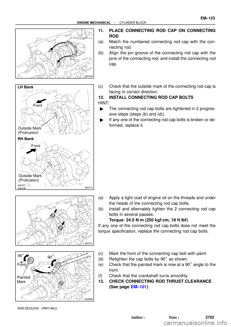
11. PLACE CONNECTING ROD CAP ON CONNECTING
ROD
(a) Match the numbered connecting rod cap with the con-
necting rod.
(b) Align the pin groove of the connecting rod cap with the
pins of the connecting rod, and install the connecting rod
cap.
(c) Check that the outside mark of the connecting rod cap is
facing in correct direction.
12. INSTALL CONNECTING ROD CAP BOLTS
HINT:
�The connecting rod cap bolts are tightened in 2 progres-
sive steps (steps (b) and (d)).
�If any one of the connecting rod cap bolts is broken or de-
formed, replace it.
(a) Apply a light coat of engine oil on the threads and under
the heads of the connecting rod cap bolts.
(b) Install and alternately tighten the 2 connecting rod cap
bolts in several passes.
Torque: 24.5 N´m (250 kgf´cm, 18 ft´lbf)
If any one of the connecting rod cap bolts does not meet the
torque specification, replace the connecting rod cap bolts.
(c) Mark the front of the connecting cap bolt with paint.
(d) Retighten the cap bolts by 90° as shown.
(e) Check that the painted mark is now at a 90° angle to the
front.
(f) Check that the crankshaft turns smoothly.
13. CHECK CONNECTING ROD THRUST CLEARANCE
(See page EM±101)
Page 3061 of 4323
R13200
FIPG
R13416
SST
R13415
± SUSPENSION AND AXLEFRONT DIFFERENTIAL CARRIER
SA±57
3053 Author�: Date�:
2005 SEQUOIA (RM1146U)
20. INSTALL DIFFERENTIAL CASE
21. INSTALL SIDE BEARING RETAINER
(a) Remove any old FIPG material and be careful not to drop
oil on the contact surfaces of the differential carrier and
side bearing retainer.
(b) Clean both installation surfaces with gasoline or alcohol.
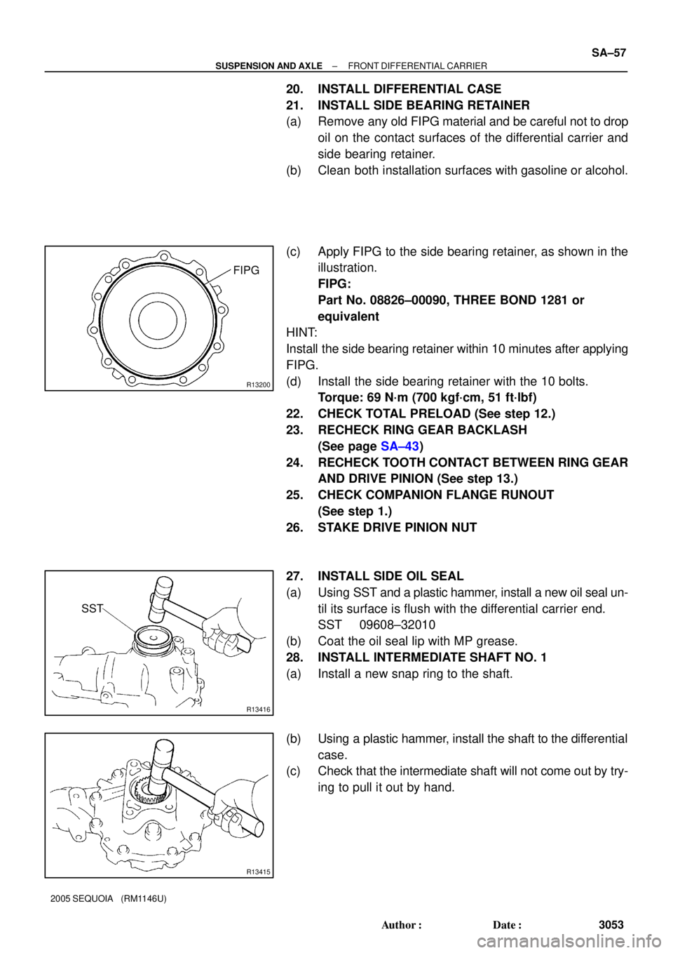
(c) Apply FIPG to the side bearing retainer, as shown in the
illustration.
FIPG:
Part No. 08826±00090, THREE BOND 1281 or
equivalent
HINT:
Install the side bearing retainer within 10 minutes after applying
FIPG.
(d) Install the side bearing retainer with the 10 bolts.
Torque: 69 N´m (700 kgf´cm, 51 ft´lbf)
22. CHECK TOTAL PRELOAD (See step 12.)
23. RECHECK RING GEAR BACKLASH
(See page SA±43)
24. RECHECK TOOTH CONTACT BETWEEN RING GEAR
AND DRIVE PINION (See step 13.)
25. CHECK COMPANION FLANGE RUNOUT
(See step 1.)
26. STAKE DRIVE PINION NUT
27. INSTALL SIDE OIL SEAL
(a) Using SST and a plastic hammer, install a new oil seal un-
til its surface is flush with the differential carrier end.
SST 09608±32010
(b) Coat the oil seal lip with MP grease.
28. INSTALL INTERMEDIATE SHAFT NO. 1
(a) Install a new snap ring to the shaft.
(b) Using a plastic hammer, install the shaft to the differential
case.
(c) Check that the intermediate shaft will not come out by try-
ing to pull it out by hand.
Page 3184 of 4323
F13902
BR109±04
F13896
Adjusting
Nut
Lock Nut
± BRAKEPARKING BRAKE PEDAL
BR±9
3176 Author�: Date�:
2005 SEQUOIA (RM1146U)
PARKING BRAKE PEDAL
ON±VEHICLE INSPECTION
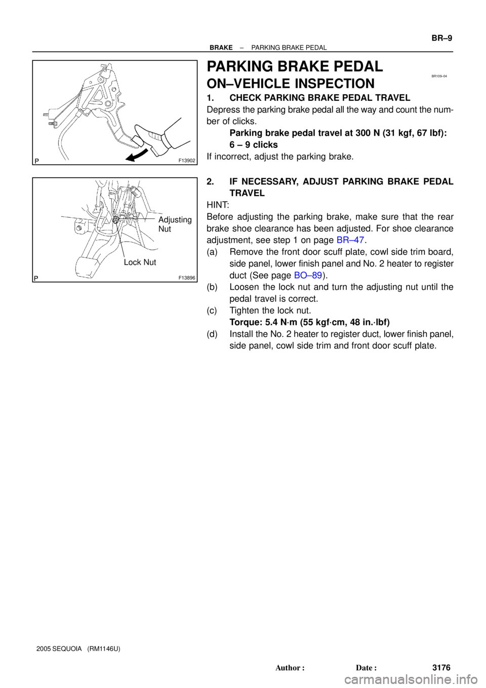
1. CHECK PARKING BRAKE PEDAL TRAVEL
Depress the parking brake pedal all the way and count the num-
ber of clicks.
Parking brake pedal travel at 300 N (31 kgf, 67 lbf):
6 ± 9 clicks
If incorrect, adjust the parking brake.
2. IF NECESSARY, ADJUST PARKING BRAKE PEDAL
TRAVEL
HINT:
Before adjusting the parking brake, make sure that the rear
brake shoe clearance has been adjusted. For shoe clearance
adjustment, see step 1 on page BR±47.
(a) Remove the front door scuff plate, cowl side trim board,
side panel, lower finish panel and No. 2 heater to register
duct (See page BO±89).
(b) Loosen the lock nut and turn the adjusting nut until the
pedal travel is correct.
(c) Tighten the lock nut.
Torque: 5.4 N´m (55 kgf´cm, 48 in.´lbf)
(d) Install the No. 2 heater to register duct, lower finish panel,
side panel, cowl side trim and front door scuff plate.