Page 2094 of 4323

DI3IO±11
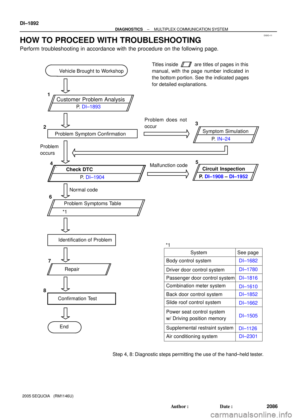
Customer Problem Analysis
Vehicle Brought to Workshop
Problem Symptom ConfirmationSymptom Simulation Problem does not
occur
Check DTC
Normal code
Problem Symptoms Table
Identification of Problem
Repair
Confirmation Test
EndTitles inside
are titles of pages in this
manual, with the page number indicated in
the bottom portion. See the indicated pages
for detailed explanations.
1
23
4
6
8P. IN±24
*1P. DI±1893
P. DI±1904Malfunction code
Problem
occurs
Circuit Inspection
P. DI±1908 ± DI±1952
See page
Body control system
Driver door control system
Passenger door control systemSystem
DI±1682
DI±1780
DI±1816
DI±1610
Step 4, 8: Diagnostic steps permitting the use of the hand±held tester.*15
7
Combination meter system
Slide roof control system
DI±1662 DI±1852 Back door control system
Power seat control system
w/ Driving position memoryDI±1505
Supplemental restraint system
Air conditioning systemDI±1126
DI±2301 DI±1892
± DIAGNOSTICSMULTIPLEX COMMUNICATION SYSTEM
2086 Author�: Date�:
2005 SEQUOIA (RM1146U)
HOW TO PROCEED WITH TROUBLESHOOTING
Perform troubleshooting in accordance with the procedure on the following page.
Page 2118 of 4323
DI±1916
± DIAGNOSTICSMULTIPLEX COMMUNICATION SYSTEM
2110 Author�: Date�:
2005 SEQUOIA (RM1146U)
INSPECTION PROCEDURE
1 Check apparatus.
CHECK:
Choose the apparatus to be inspected.
ApparatusGo to step
w/ Sliding roofA
w/o Sliding roofB
B Go to step 4.
A
2 Check the communication circuit inside the sliding roof control ECU.
PREPARATION:
Disconnect connector ºS19º of the sliding roof control ECU.
CHECK:
Check the DTC (See page DI±1904).
OK:
DTCs B1214 and/or B1215 are not indicated.
HINT:
Ignore any codes other than DTCs B1214 and B1215.
OK Replace sliding roof control ECU.
NG
3 Check for a short circuit between the sliding control ECU and body ECU.
PREPARATION:
(a) Reconnect connector ºS19º of the sliding roof control ECU (only vehicles w/ sliding roof).
(b) Disconnect connector ºB7º of the body ECU.
CHECK:
Check the DTC (See page DI±1904).
OK:
DTCs B1214 and/or B1215 are not indicated.
HINT:
Ignore any codes other than DTCs B1214 and B1215.
Page 2164 of 4323

DID9N±01
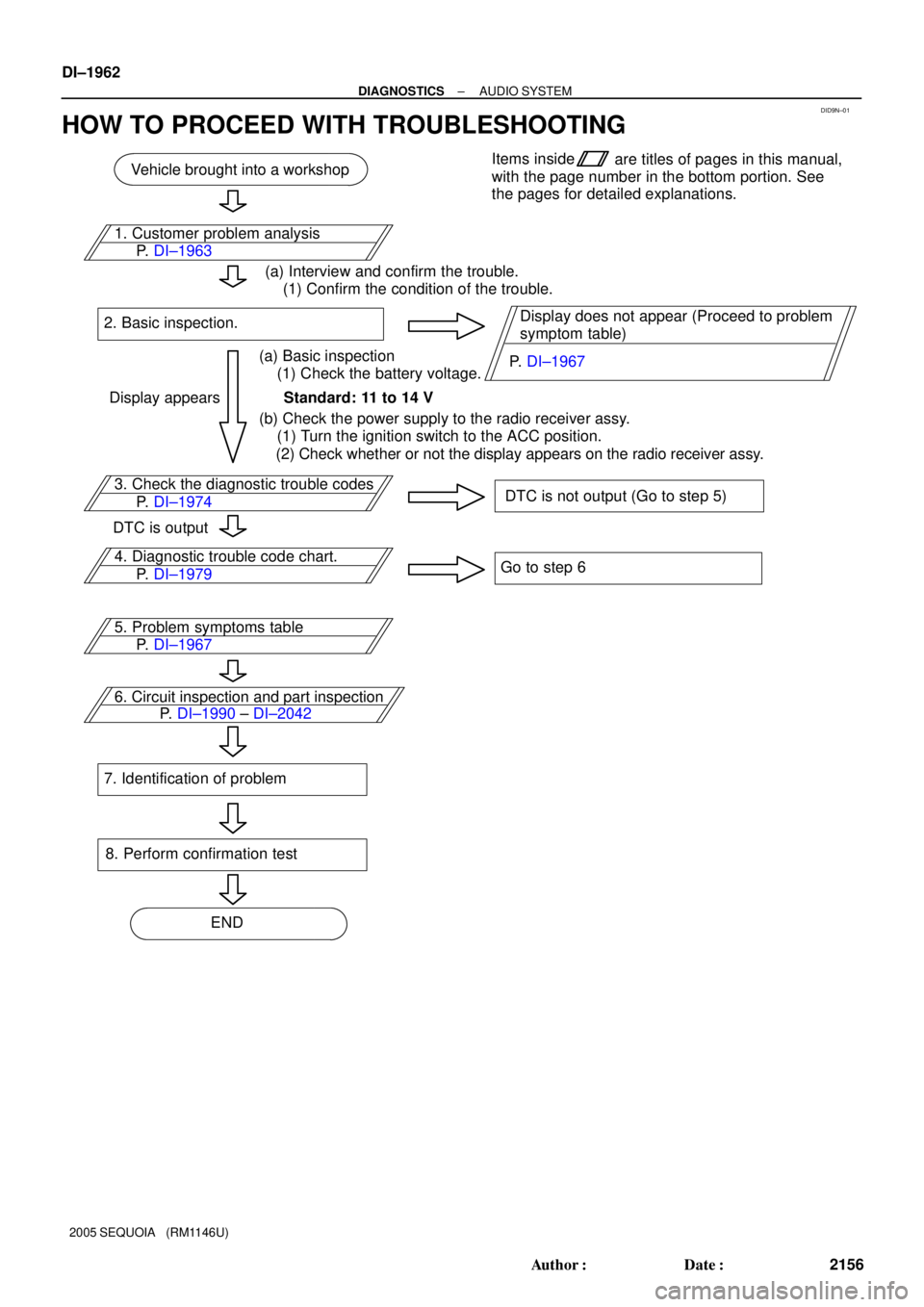
Vehicle brought into a workshop
3. Check the diagnostic trouble codes
DTC is not output (Go to step 5)
4. Diagnostic trouble code chart.
Go to step 6
6. Circuit inspection and part inspection
8. Perform confirmation test
ENDItems inside
are titles of pages in this manual,
with the page number in the bottom portion. See
the pages for detailed explanations.
P. DI±1974
P. DI±1990 ± DI±2042 P. DI±1979 1. Customer problem analysis
P. DI±1963
(a) Interview and confirm the trouble.
(1) Confirm the condition of the trouble.
(a) Basic inspection
(1) Check the battery voltage. 2. Basic inspection.
Standard: 11 to 14 V
(b) Check the power supply to the radio receiver assy.
(1) Turn the ignition switch to the ACC position.
(2) Check whether or not the display appears on the radio receiver assy.Display does not appear (Proceed to problem
symptom table)
Display appears
DTC is output
5. Problem symptoms table
P. DI±1967
7. Identification of problem
P. DI±1967 DI±1962
± DIAGNOSTICSAUDIO SYSTEM
2156 Author�: Date�:
2005 SEQUOIA (RM1146U)
HOW TO PROCEED WITH TROUBLESHOOTING
Page 2250 of 4323
DIDAI±01
Vehicle brought into a workshop
4. Check the diagnostic trouble codes
DTC is not output (Go to step 6)
5. Diagnostic trouble code chart
Go to step 7
7. Circuit inspection and part inspection
10. Perform confirmation test
ENDItems inside
are titles of pages in this manual,
with the page number in the bottom portion. See
the pages for detailed explanations.
P. DI±2053
P. DI±2058 ± DI±2076 P. DI±1979, DI±2203 1. Customer problem analysis
P. DI±2049
2. Problem Symptoms Confirmation
Symptom does
not occur
Malfunction
code
6. Problem symptoms table
P. DI±2050
8. Identification of problem
Symptom occursGo to step 4
3. Symptom Simulation
P. IN±24
9. Repair or replace
Normal system
code DI±2048
± DIAGNOSTICSREAR SEAT AUDIO SYSTEM
2242 Author�: Date�:
2005 SEQUOIA (RM1146U)
HOW TO PROCEED WITH TROUBLESHOOTING
Page 2285 of 4323
DIDAW±01
Vehicle brought into a workshop
4. Check the diagnostic trouble codes
DTC is not output (Go to step 6)
5. Diagnostic trouble code chart.
Go to step 7
7. Circuit inspection and part inspection
10. Perform confirmation test
ENDItems inside
are titles of pages in this manual,
with the page number in the bottom portion. See
the pages for detailed explanations.
P. DI±2097
P. DI±2107 ± DI±2157 P. DI±2103 1. Customer problem analysis
P. DI±2084
2. Problem Symptom Confirmation
Symptom does
not occur
Malfunction
code
6. Problem symptoms table
P. DI±2087
8. Identification of problem
Symptom occursGo to step 4
3. Symptom Simulation
P. IN±24
9. Repair or replace
Normal system
code
± DIAGNOSTICSREAR SEAT ENTERTAINMANT SYSTEM
DI±2083
2277 Author�: Date�:
2005 SEQUOIA (RM1146U)
HOW TO PROCEED WITH TROUBLESHOOTING
Page 2374 of 4323

DIDBS±01
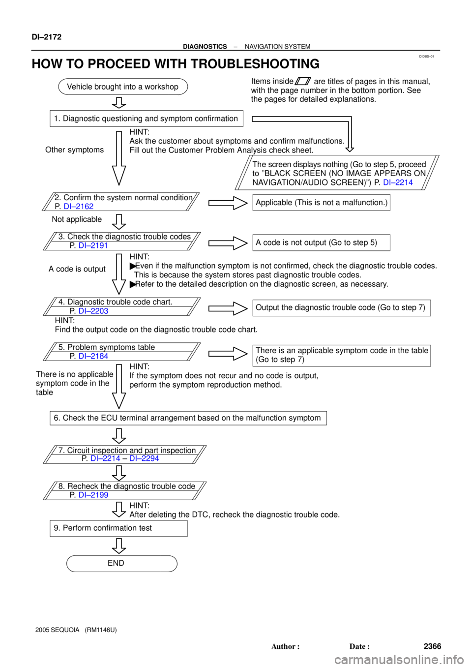
Vehicle brought into a workshop
1. Diagnostic questioning and symptom confirmation
HINT:
Ask the customer about symptoms and confirm malfunctions.
Fill out the Customer Problem Analysis check sheet.
The screen displays nothing (Go to step 5, proceed
to ºBLACK SCREEN (NO IMAGE APPEARS ON
NAVIGATION/AUDIO SCREEN)º) P. DI±2214 Other symptoms
2. Confirm the system normal condition
P. DI±2162Applicable (This is not a malfunction.)
Not applicable
3. Check the diagnostic trouble codes
HINT:
� Even if the malfunction symptom is not confirmed, check the diagnostic trouble codes.
This is because the system stores past diagnostic trouble codes.
� Refer to the detailed description on the diagnostic screen, as necessary. A code is outputA code is not output (Go to step 5)
4. Diagnostic trouble code chart.
HINT:
Find the output code on the diagnostic trouble code chart.Output the diagnostic trouble code (Go to step 7)
5. Problem symptoms table
HINT:
If the symptom does not recur and no code is output,
perform the symptom reproduction method.There is an applicable symptom code in the table
(Go to step 7)
There is no applicable
symptom code in the
table
6. Check the ECU terminal arrangement based on the malfunction symptom
7. Circuit inspection and part inspection
8. Recheck the diagnostic trouble code
HINT:
After deleting the DTC, recheck the diagnostic trouble code.
9. Perform confirmation test
ENDItems inside
are titles of pages in this manual,
with the page number in the bottom portion. See
the pages for detailed explanations.
P. DI±2191
P. DI±2214 ± DI±2294 P. DI±2203
P. DI±2184
P. DI±2199
DI±2172
± DIAGNOSTICSNAVIGATION SYSTEM
2366 Author�: Date�:
2005 SEQUOIA (RM1146U)
HOW TO PROCEED WITH TROUBLESHOOTING
Page 2516 of 4323

DIDKS±01
DI±2314
± DIAGNOSTICSAIR CONDITIONING SYSTEM
2508 Author�: Date�:
2005 SEQUOIA (RM1146U)
DATA LIST / ACTIVE TEST
1. DATA LIST
HINT:
From the DATA LIST displayed on the hand±held tester, you can read the values of the displays, sensors,
actuators and so on without part removal. Reading the DATA LIST as the first step of troubleshooting is one
way to shorten labor time.
(a) Connect the hand±held tester to the DLC3.
(b) Turn the ignition switch to the ON position.
(c) From the display on the tester, select ºDATA LISTº.
AIR CONDITIONING:
ItemMeasurement Item / Display
(Range)Normal ConditionDiagnostic Note
ROOM TEMP
Room temperature sensor /
min.: ±6.5°C (20.3°F)
max.: 57.25°C (135.05°F)Actual room temperature is dis-
played
Open in the circuit:
±6.5°C (20.3°F)
Short in the circuit:
57.25°C (135.05°F)
AMBI TEMP SENS
Ambient temperature sensor /
min.: ±30.8°C (±23.44°F)
max.: 50.8°C (123.44°F)Actual ambient temperature is dis-
played
Open in the circuit:
±30.8°C (±23.44°F)
Short in the circuit:
50.8°C (123.44°F)
EVAP TEMP
Evaporator temperature sensor /
min.: ±29.7°C (±21.46°F)
max.: 59.55°C (139.19°F)Actual evaporator temperature is
displayed
Open in the circuit:
±29.7°C (±21.46°F)
Short in the circuit:
59.55°C (139.19°F)
SOLAR SENS±DSolar sensor (Driver side) /
min.: 0 max.: 255Increases as brightness increasesOpen in the circuit: 0
Short in the circuit: 255
COOLANT TEMP
Engine coolant temperature /
min.: 1.3°C (34.34°F)
max.: 90.55°C (194.99°F)Actual engine coolant temperature
is displayed while the engine is
warmed up
±
SET TEMP±DSet temperature (Driver side) /
min.: 0 max.: 255Set temperature and displayed
temperature are the same±
ESTIMATE TEMP±D
Estimated temperature (Driver
side) / min.: ±200°C (±328°F)
max.: 200°C (392°F)Damper is at ºMAX. COOLº:
±200°C (±328°F)
Damper is at ºMAX. HOTº:
200°C (392°F)
±
A/M DAMP POS±DAir mix damper position (Driver
side) / min.: ±14% max.: 113.5%
Damper is at ºMAX. COOLº:
±10.0%
Damper is at ºMAX. HOTº:
100.0%
±
A/I DAMP POSAir inlet damper position /
min.: ±9% max.: 109%
Damper is at ºRECIRCULATIONº:
±9%
Damper is at ºFRESHº: 109.0%
Damper is at ºHALF±RECIR-
CULATIONº: 30.0 to 80.0%
Open in the circuit: 50.0%
A/M DAMP TARG±D
Air mix damper target position
(Driver side) /
min.: ±14% max.: 113.5%Damper is at ºMAX. COOLº:
±10.0%
Damper is at ºMAX. HOTº:
100.0%
±
A/I DAMP TARGAir inlet damper target position /
min.: ±9% max.: 109%
Damper is at ºRECIRCULATIONº:
±9%
Damper is at ºFRESHº: 109.0%
Damper is at ºHALF±RECIR-
CULATIONº: 30.0 to 80.0%
Open in the circuit: 50.0%
Page 2518 of 4323
DI±2316
± DIAGNOSTICSAIR CONDITIONING SYSTEM
2510 Author�: Date�:
2005 SEQUOIA (RM1146U)
2. ACTIVE TEST
HINT:
Performing the ACTIVE TEST using the hand±held tester allows the relay, VSV, actuator and so on to oper-
ate without part removal. Performing the ACTIVE TEST as the first step of troubleshooting is one way to
shorten labor time.
(a) Connect the hand±held tester to the DLC3.
(b) Turn the ignition switch to the ON position.
(c) From the display on the tester, perform the ºACTIVE TESTº.
AIR CONDITIONING:
ItemTest Details / Display (Range)Diagnostic Note
BLOWER MOTORBlower motor / min.: 0 max.: 31±
AIR MIX DAMP±DAir mix damper (Driver side) / min.: ±14% max.: 113.5%±
A/I DAMP±LINEARAir inlet damper position (Linear) / min.: ±14% max.: 113.5%±
REAR BLOWERBlower motor (Rear) / min.: 0 max.: 31±
AIR MIX DAMP±RAir mix damper (Rear) / min.: ±14% max.: 113.5%±
A/C MAG CLUTCHA/C magnetic clutch relay / OFF, ON±
DEFOGGER RLY±RDefogger relay (Rear) / OFF, ON±