Page 1665 of 4323
H01019H43108H23604
P/T Squib RH
PR±
PR+Airbag
Sensor
Assembly
Floor Wire
B C
DA
P11
± DIAGNOSTICSSUPPLEMENTAL RESTRAINT SYSTEM
DI±1463
1657 Author�: Date�:
2005 SEQUOIA (RM1146U)
6 Check floor wire (short to B+).
PREPARATION:
Connect the negative (±) terminal cable to the battery, and wait
for at least 2 seconds.
CHECK:
(a) Turn the ignition switch to the ON position.
(b) Measure the voltage according to the value(s) in the table
below.
OK:
Tester ConnectionConditionSpecified Condition
P11±1 (PR+) ±
Body groundIgnition switch ONBelow 1 V
P11±2 (PR±) ±
Body groundIgnition switch ONBelow 1 V
NG Repair or replace floor wire.
OK
Go to step 11.
7 Check connector.
CHECK:
Check that the floor wire connector (on the front seat outer belt RH side) is not damaged.
OK:
The lock button is not disengaged, or the claw of the lock is not deformed or damaged.
NG Repair or replace floor wire.
OK
Page 1670 of 4323

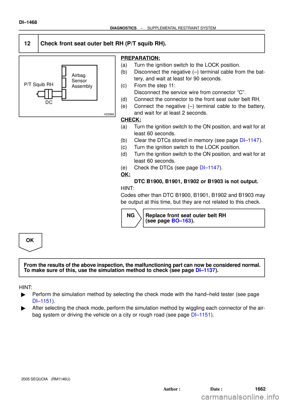
H23966
Airbag
Sensor
Assembly
C D P/T Squib RH
DI±1468
± DIAGNOSTICSSUPPLEMENTAL RESTRAINT SYSTEM
1662 Author�: Date�:
2005 SEQUOIA (RM1146U)
12 Check front seat outer belt RH (P/T squib RH).
PREPARATION:
(a) Turn the ignition switch to the LOCK position.
(b) Disconnect the negative (±) terminal cable from the bat-
tery, and wait at least for 90 seconds.
(c) From the step 11:
Disconnect the service wire from connector ºCº.
(d) Connect the connector to the front seat outer belt RH.
(e) Connect the negative (±) terminal cable to the battery,
and wait for at least 2 seconds.
CHECK:
(a) Turn the ignition switch to the ON position, and wait for at
least 60 seconds.
(b) Clear the DTCs stored in memory (see page DI±1147).
(c) Turn the ignition switch to the LOCK position.
(d) Turn the ignition switch to the ON position, and wait for at
least 60 seconds.
(e) Check the DTCs (see page DI±1147).
OK:
DTC B1900, B1901, B1902 or B1903 is not output.
HINT:
Codes other than DTC B1900, B1901, B1902 and B1903 may
be output at this time, but they are not related to this check.
NG Replace front seat outer belt RH
(see page BO±163).
OK
From the results of the above inspection, the malfunctioning part can now be considered normal.
To make sure of this, use the simulation method to check (see page DI±1137).
HINT:
�Perform the simulation method by selecting the check mode with the hand±held tester (see page
DI±1151).
�After selecting the check mode, perform the simulation method by wiggling each connector of the air-
bag system or driving the vehicle on a city or rough road (see page DI±1151).
Page 1673 of 4323

± DIAGNOSTICSSUPPLEMENTAL RESTRAINT SYSTEM
DI±1471
1665 Author�: Date�:
2005 SEQUOIA (RM1146U)
INSPECTION PROCEDURE
CAUTION:
Be sure to perform the following procedures before troubleshooting to avoid unexpected airbag de-
ployment.
(a) Turn the ignition switch to the LOCK position.
(b) Disconnect the negative (±) terminal cable from the battery, and wait for at least 90 seconds.
(c) Disconnect the connectors from the airbag sensor assembly.
(d) Disconnect the connectors from the steering wheel pad.
(e) Disconnect the connectors from the front passenger airbag assembly.
(f) w/ Side and curtain shield airbag:
Disconnect the connectors from the side airbag assembly LH and RH.
(g) w/ Side and curtain shield airbag:
Disconnect the connectors from the curtain shield airbag assembly LH and RH.
(h) Disconnect the connectors from the front seat outer belt LH and RH.
1 Check DTC.
CHECK:
(a) Proceed to each step according to how to read DTC.
(1) If using the hand±held tester (read the 5±digit of DTC):
Using the hand±held tester, check the DTCs (see page DI±1147).
RESULT:
DTC B1905 is output.A
DTC B1906 is output.B
DTC B1907 is output.C
DTC B1908 is output.D
(2) If not using the hand±held tester (read the 2±digit of DTC):
Check the DTCs (see page DI±1147).
RESULT:
DTC 74 is output.E
HINT:
Codes other than DTC B1905, B1906, B1907, B1908 and DTC 74 may be output at this time, but they are
not related to this check.
B Go to step 4.
C Go to step 5.
D Go to step 6.
E Go to step 7.
A
Page 1674 of 4323
H01016H43108H23601
P/T Squib LH
PL±
PL+Airbag
Sensor
Assembly
Floor Wire No. 2
A
B C D
P10
DI±1472
± DIAGNOSTICSSUPPLEMENTAL RESTRAINT SYSTEM
1666 Author�: Date�:
2005 SEQUOIA (RM1146U)
2 Check connector.
CHECK:
Check that the floor wire No. 2 connector (on the front seat outer belt LH side) is not damaged.
OK:
The lock button is not disengaged, or the claw of the lock is not deformed or damaged.
NG Repair or replace floor wire No. 2.
OK
3 Check floor wire No. 2 (short).
PREPARATION:
Release the activation prevention mechanism built into con-
nector ºBº (see page DI±1137).
CHECK:
Measure the resistance according to the value(s) in the table
below.
OK:
Tester ConnectionConditionSpecified Condition
P10±1 (PL+) ±
P10±2 (PL±)Always1 MW or Higher
NG Repair or replace floor wire No. 2.
OK
Go to step 10.
Page 1676 of 4323
H01016H43108H23601
P/T Squib LH
PL±
PL+Airbag
Sensor
Assembly
Floor Wire No. 2
A
B C D
P10
DI±1474
± DIAGNOSTICSSUPPLEMENTAL RESTRAINT SYSTEM
1668 Author�: Date�:
2005 SEQUOIA (RM1146U)
6 Check floor wire No. 2 (short to B+).
PREPARATION:
Connect the negative (±) terminal cable to the battery, and wait
for at least 2 seconds.
CHECK:
(a) Turn the ignition switch to the ON position.
(b) Measure the voltage according to the value(s) in the table
below.
OK:
Tester ConnectionConditionSpecified Condition
P10±1 (PL+) ±
Body groundIgnition switch ONBelow 1 V
P10±2 (PL±) ±
Body groundIgnition switch ONBelow 1 V
NG Repair or replace floor wire No. 2.
OK
Go to step 11.
7 Check connector.
CHECK:
Check that the floor wire No. 2 connector (on the front seat outer belt LH side) is not damaged.
OK:
The lock button is not disengaged, or the claw of the lock is not deformed or damaged.
NG Repair or replace floor wire No. 2.
OK
Page 1681 of 4323

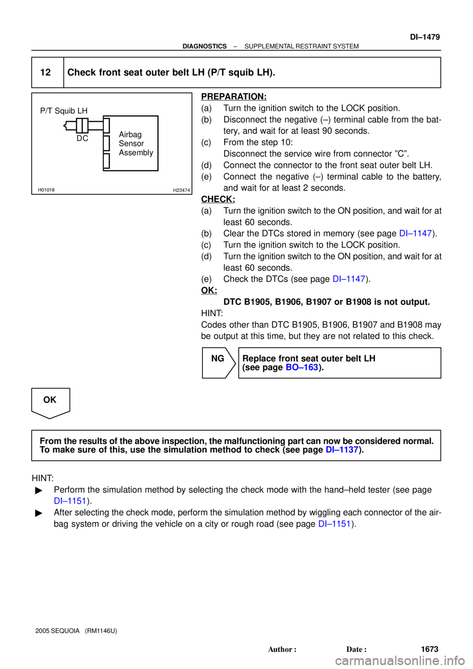
H01018H23474
Airbag
Sensor
Assembly DC P/T Squib LH
± DIAGNOSTICSSUPPLEMENTAL RESTRAINT SYSTEM
DI±1479
1673 Author�: Date�:
2005 SEQUOIA (RM1146U)
12 Check front seat outer belt LH (P/T squib LH).
PREPARATION:
(a) Turn the ignition switch to the LOCK position.
(b) Disconnect the negative (±) terminal cable from the bat-
tery, and wait for at least 90 seconds.
(c) From the step 10:
Disconnect the service wire from connector ºCº.
(d) Connect the connector to the front seat outer belt LH.
(e) Connect the negative (±) terminal cable to the battery,
and wait for at least 2 seconds.
CHECK:
(a) Turn the ignition switch to the ON position, and wait for at
least 60 seconds.
(b) Clear the DTCs stored in memory (see page DI±1147).
(c) Turn the ignition switch to the LOCK position.
(d) Turn the ignition switch to the ON position, and wait for at
least 60 seconds.
(e) Check the DTCs (see page DI±1147).
OK:
DTC B1905, B1906, B1907 or B1908 is not output.
HINT:
Codes other than DTC B1905, B1906, B1907 and B1908 may
be output at this time, but they are not related to this check.
NG Replace front seat outer belt LH
(see page BO±163).
OK
From the results of the above inspection, the malfunctioning part can now be considered normal.
To make sure of this, use the simulation method to check (see page DI±1137).
HINT:
�Perform the simulation method by selecting the check mode with the hand±held tester (see page
DI±1151).
�After selecting the check mode, perform the simulation method by wiggling each connector of the air-
bag system or driving the vehicle on a city or rough road (see page DI±1151).
Page 1713 of 4323

DIDGG±01
± DIAGNOSTICSPOWER SEAT CONTROL SYSTEM (w/ Driving Position
Memory)DI±1511
1705 Author�: Date�:
2005 SEQUOIA (RM1146U)
DATA LIST / ACTIVE TEST
1. DATA LIST
HINT:
Using the DATA LIST displayed on the hand±held tester, you can read the value of the switch, sensor, etc.
without parts removal. Reading the DATA LIST as the first step of troubleshooting is one way to shorten the
labor time.
(a) Connect the hand±held tester to the DLC3.
(b) Turn the ignition switch ON.
(c) Read the DATA LIST according to the display on the tester.
D±SEAT:
ItemMeasurement Item/
Display (Range)Normal Condition
RECLIN SW REARReclining switch signal (Rearward)/
ON or OFFON: Reclining switch (Rearward) is ON
OFF: Reclining switch (Rearward) is OFF
RECLIN SW FRONTReclining switch signal (Forward)/
ON or OFFON: Reclining switch (Forward) is ON
OFF: Reclining switch (Forward) is OFF
F VTCL SW DOWNFront vertical switch signal (Downward)/
ON or OFFON: Front vertical switch (Downward) is ON
OFF: Front vertical switch (Downward) is OFF
F VTCL SW UPFront vertical switch signal (Upward)/
ON or OFFON: Front vertical switch (Upward) is ON
OFF: Front vertical switch (Upward) is OFF
LIFTER SW DOWNLifter switch signal (Downward)/
ON or OFFON: Lifter switch (Downward) is ON
OFF: Lifter switch (Downward) is OFF
LIFTER SW UPLifter switch signal (Upward)/
ON or OFFON: Lifter switch (Upward) is ON
OFF: Lifter switch (Upward) is OFF
SLIDE SW REARSliding switch signal (Rearward)/
ON or OFFON: Sliding switch (Rearward) is ON
OFF: Sliding switch (Rearward) is OFF
SLIDE SW FRONTSliding switch signal (Forward)/
ON or OFFON: Sliding switch (Forward) is ON
OFF: Sliding switch (Forward) is OFF
POWER VOLTAGEPower supply for position control ECU & switch/
MIN: 0 V, MAX: 19.89 VWithin range from 11 V to 14 V
IG SWIgnition switch status/
ON or OFFON Ignition switch is ON
OFF: Ignition switch is OFF
KEY UNLOCK SWKey unlock warning switch signal/
ON or OFFON: Key is in ignition key cylinder
OFF: Key is not in ignition key cylinder
D±DOOR WARN SWDoor courtesy switch signal/
ON or OFFON: Driver side door is open
OFF: Driver side door is closed
PNP SWPark/neutral position switch signal/
ON or OFFON: Shift lever in neutral position
OFF: Shift lever in any position except neutral
M2 SWSeat memory switch M2 signal/
ON or OFFON: Seat memory switch M2 is ON
OFF: Seat memory switch M2 is OFF
M1 SWSeat memory switch M1 signal/
ON or OFFON: Seat memory switch M1 is ON
OFF: Seat memory switch M1 is OFF
SET SWSeat memory set switch signal/
ON or OFFON: Memory set switch is ON
OFF: Memory set switch is OFF
SLIDE POSSeat sliding position/
MIN: ±4096, MAX: 4096Within range from ±4096 to 4096
RECLN POSSeatback position/
MIN: ±4096, MAX: 4096Within range from ±4096 to 4096
F VTCL POSSeat front vertical position/
MIN: ±4096 MAX: 4096Within range from ±4096 to 4096
LIFTER POSSeat lifter position/
MIN: ±4096 MAX: 4096Within range from ±4096 to 4096
MEM M1 SW
Driving position memorized with seat memory
switch M1/
MEM or NOT MEMMEM: Memorized
NOT MEM: Not memorized
Page 1739 of 4323
DI26R±41
Customer Problem Analysis
Check and Clear DTC
Vehicle Brought to Workshop
Problem Symptom ConfirmationSymptom Simulation Symptom does not occur
DTC CheckNormal system code
DTC Chart
Problem Symptoms Table
Circuit InspectionInput Signal Check
Parts Inspection
Identification of Problem
Repair
Confirmation Test
EndItems inside
are titles of pages in this
manual with the page number indicated in the
bottom portion. See the indicated pages for
detailed explanations. 1
2
34
5
6
7
89
10
Step 2, 5, 8, 10: Diagnostic steps permitting use of
the hand±held tester. P. DI±1538
P. DI±1545
P. DI±1545
P. DI±1549
P. IN±24
P. DI±1541
P. DI±1551 ± DI±1567
OKNG
Symptom occurs
Trouble code
± DIAGNOSTICSCRUISE CONTROL SYSTEM
DI±1537
1731 Author�: Date�:
2005 SEQUOIA (RM1146U)
HOW TO PROCEED WITH TROUBLESHOOTING
Troubleshoot in accordance with the following procedures: