Page 3366 of 4323
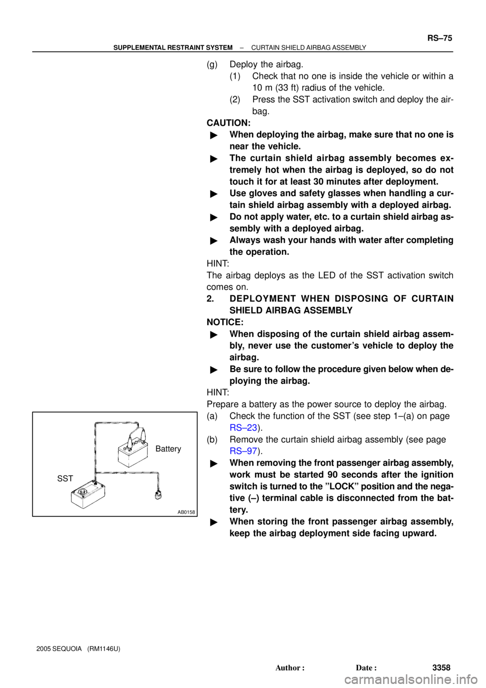
AB0158
Battery
SST
± SUPPLEMENTAL RESTRAINT SYSTEMCURTAIN SHIELD AIRBAG ASSEMBLY
RS±75
3358 Author�: Date�:
2005 SEQUOIA (RM1146U)
(g) Deploy the airbag.
(1) Check that no one is inside the vehicle or within a
10 m (33 ft) radius of the vehicle.
(2) Press the SST activation switch and deploy the air-
bag.
CAUTION:
�When deploying the airbag, make sure that no one is
near the vehicle.
�The curtain shield airbag assembly becomes ex-
tremely hot when the airbag is deployed, so do not
touch it for at least 30 minutes after deployment.
�Use gloves and safety glasses when handling a cur-
tain shield airbag assembly with a deployed airbag.
�Do not apply water, etc. to a curtain shield airbag as-
sembly with a deployed airbag.
�Always wash your hands with water after completing
the operation.
HINT:
The airbag deploys as the LED of the SST activation switch
comes on.
2. DEPLOYMENT WHEN DISPOSING OF CURTAIN
SHIELD AIRBAG ASSEMBLY
NOTICE:
�When disposing of the curtain shield airbag assem-
bly, never use the customer's vehicle to deploy the
airbag.
�Be sure to follow the procedure given below when de-
ploying the airbag.
HINT:
Prepare a battery as the power source to deploy the airbag.
(a) Check the function of the SST (see step 1±(a) on page
RS±23).
(b) Remove the curtain shield airbag assembly (see page
RS±97).
�When removing the front passenger airbag assembly,
work must be started 90 seconds after the ignition
switch is turned to the ºLOCKº position and the nega-
tive (±) terminal cable is disconnected from the bat-
tery.
�When storing the front passenger airbag assembly,
keep the airbag deployment side facing upward.
Page 3448 of 4323

BE2DD±03
I12796
Right Turn
2 4 5 7 8
9 631
10 11 12 13 14 15 16 17
Left Turn
I04046
Wire Harness Side: BE±36
± BODY ELECTRICALTURN SIGNAL AND HAZARD WARNING SYSTEM
3440 Author�: Date�:
2005 SEQUOIA (RM1146U)
INSPECTION
1. INSPECT TURN SIGNAL SWITCH CONTINUITY
Switch positionTester connectionSpecified condition
Left turn1 ± 2Continuity
Neutral±No continuity
Right turn2 ± 3Continuity
If continuity is not as specified, replace the switch.
2. Connector disconnected:
INSPECT TURN SIGNAL FLASHER CIRCUIT
Disconnect the connector from the turn signal flasher and in-
spect the connector on the wire harness side as shown in the
table below.
Tester connectionConditionSpecified condition
1 ± GroundIgnition switch LOCK or ACCNo voltage
1 ± GroundIgnition switch ONBattery positive voltage
2 ± GroundAlwaysContinuity
3 ± GroundAlwaysContinuity
4 ± GroundAlwaysBattery positive voltage
5 ± GroundTurn signal switch RIGHT or OFFNo Continuity
5 ± GroundTurn signal switch LEFTContinuity
6 ± GroundTurn signal switch LEFT or OFFNo Continuity
6 ± GroundTurn signal switch RIGHTContinuity
7 ± GroundAlwaysContinuity
8 ± GroundHazard warning switch OFFNo Continuity
8 ± GroundHazard warning switch ONContinuity
If the circuit is as specified, perform the inspection on the next
step.
If the circuit is not as specified, inspect the circuit connected to
other parts.
Page 3567 of 4323
BO45I±02
H24349N´m (kgf´cm, ft´lbf)
: Specified torque Rear Bumper
Reinforcement
95 (970, 70)
7.0 (71, 62 in.´lbf)
Quarter Wheel Opening Moulding
Rear Bumper Cover Rear Bumper Side Support
Reflex Reflector Rear Bumper Protection Rear Bumper SealBack Step Reinforcement Rear Mud Guard
Rear Bumper Side Support
19 (195, 14)
19 (195, 14)
19 (195, 14)
19 (195, 14)
7.0 (71, 62 in.´lbf)
5.0 (50, 43 in.´lbf)
95 (970, 70)
5.0 (50, 43 in.´lbf)
7.0 (71, 62 in.´lbf)
7.0 (71, 62 in.´lbf)
Side Support
Rear Bumper Extension
7.0 (71, 62 in.´lbf)
7.0 (71, 62 in.´lbf)
95 (970, 70)
95 (970, 70)
x4x4x4
x4
Rear Mud Guard
BO±6
± BODYREAR BUMPER
3559 Author�: Date�:
2005 SEQUOIA (RM1146U)
REAR BUMPER
COMPONENTS
Page 3586 of 4323
BO45T±01
H16689
Back Door Side Garnish
Back Door Center Garnishw/o Rear spoiler:
High Mount Stop Light
Outside MouldingBack Door Hingew/ Rear spoiler:
Rear Spoiler
Back Door Hinge
Rear Wiper Arm
Wiper
Motor
Grommet
Rear Wiper
Motor
Service Hole Plug
Outside MouldingStep Liner Back Door Glass Back Door Side
Garnish
Back Door Glass Run
Outer Weatherstrip
Back Door
Glass Guide Rail
Outer Cover
Power Window Regulator
Back Door
Glass Guide RailOutside Handle
Key Cylinder
Rear Light
Lower Stopper Rear Light Opening Hole Cover
Stopper Cushion
Back Door Lock ProtectorControl
Cable
Stopper Cushion
: Specified torque Strap Cover
Back Door Pull StrapBack Door Trim Board Inner WeatherstripNo. 1 Service
Hole Cover
Opening Hole Cover
19.5 (199, 14.4)
8.0 (82, 71 in.´lbf)
5.5 (56, 49 in.´lbf)
5.5 (56, 49 in.´lbf)
8.0 (82, 71 in.´lbf)
N´m (kgf´cm, ft´lbf)No. 2 Service
Hole Cover
Back Door
Handle
Protector
Licence Plate
Light
Assembly
Outside
Garnish
Washer Nozzle
Lower Stopper
Power Window
Regulator Motor
Back Door Lock
19.5 (199, 14.4)
8.0 (82, 71 in.´lbf)
± BODYBACK DOOR
BO±25
3578 Author�: Date�:
2005 SEQUOIA (RM1146U)
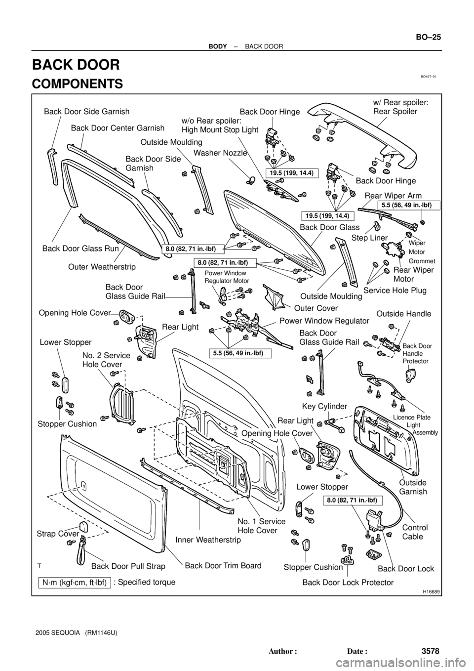
BACK DOOR
COMPONENTS
Page 3587 of 4323
H16671
BO45U±01
H16672
H16673
H16674
5 Clips
H16675
3 Clips BO±26
± BODYBACK DOOR
3579 Author�: Date�:
2005 SEQUOIA (RM1146U)
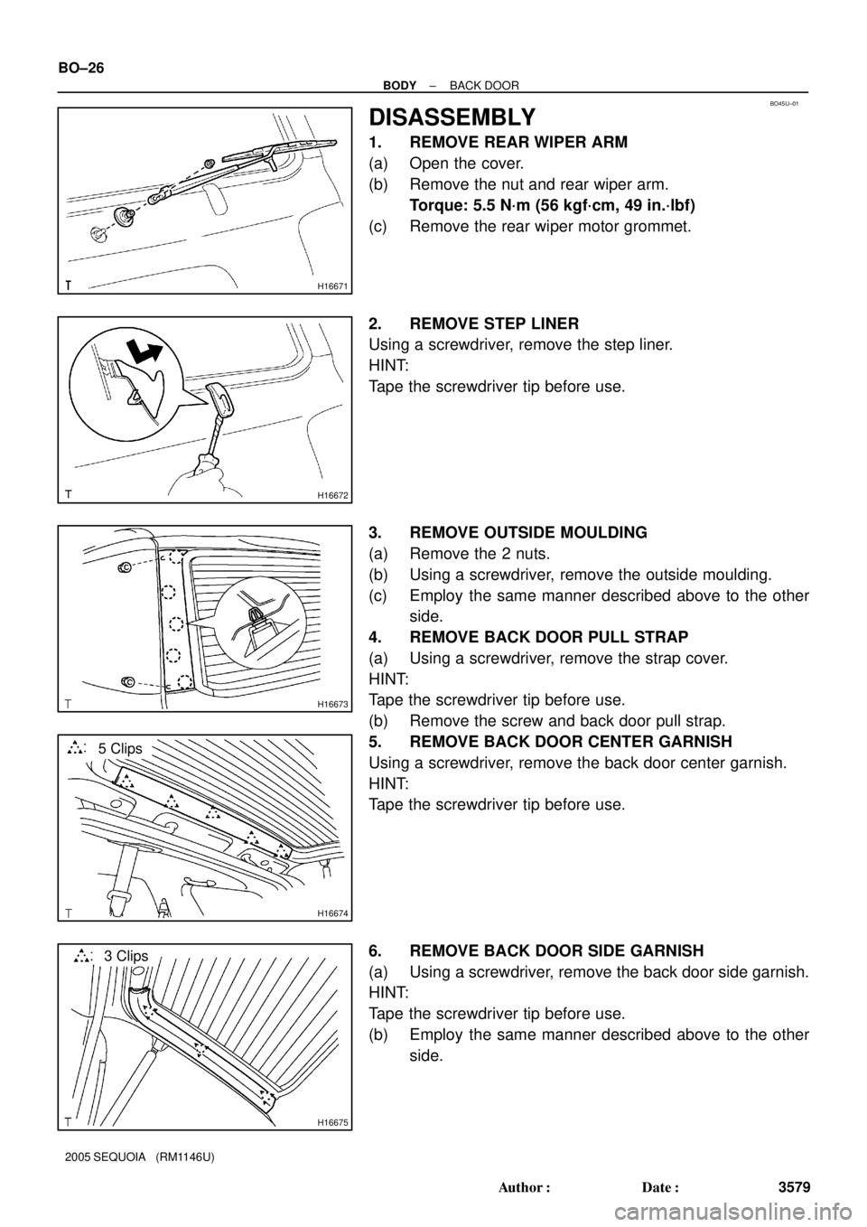
DISASSEMBLY
1. REMOVE REAR WIPER ARM
(a) Open the cover.
(b) Remove the nut and rear wiper arm.
Torque: 5.5 N´m (56 kgf´cm, 49 in.´lbf)
(c) Remove the rear wiper motor grommet.
2. REMOVE STEP LINER
Using a screwdriver, remove the step liner.
HINT:
Tape the screwdriver tip before use.
3. REMOVE OUTSIDE MOULDING
(a) Remove the 2 nuts.
(b) Using a screwdriver, remove the outside moulding.
(c) Employ the same manner described above to the other
side.
4. REMOVE BACK DOOR PULL STRAP
(a) Using a screwdriver, remove the strap cover.
HINT:
Tape the screwdriver tip before use.
(b) Remove the screw and back door pull strap.
5. REMOVE BACK DOOR CENTER GARNISH
Using a screwdriver, remove the back door center garnish.
HINT:
Tape the screwdriver tip before use.
6. REMOVE BACK DOOR SIDE GARNISH
(a) Using a screwdriver, remove the back door side garnish.
HINT:
Tape the screwdriver tip before use.
(b) Employ the same manner described above to the other
side.
Page 3600 of 4323
BO463±01
H16777
Washer Nozzle
Back Door Glass
Rear Wiper Arm Back Door Center Garnish
Back Door
Side Garnish
Power Window
Regulator
Step Liner
Service Hole CoverWiper Motor
Grommet
Rear Wiper Motor
Back Door Side Garnish
No. 2 Service
Hole Cover
Strap Cover
No. 1 Service Hole Cover
Back Door Trim Board
Back Door Pull Strap
: Specified torque
N´m (kgf´cm, ft´lbf)
5.5 (56, 49 in.´lbf)
8.0 (82, 71 in.´lbf)
5.5 (56, 49 in.´lbf)
8.0 (82, 71 in.´lbf)
± BODYREAR WIPER AND WASHER
BO±39
3592 Author�: Date�:
2005 SEQUOIA (RM1146U)
REAR WIPER AND WASHER
COMPONENTS
Page 3601 of 4323
BO464±01
H16671
H16672
H16674
5 Clips
H16675
3 Clips
H16676
10 Clips BO±40
± BODYREAR WIPER AND WASHER
3593 Author�: Date�:
2005 SEQUOIA (RM1146U)
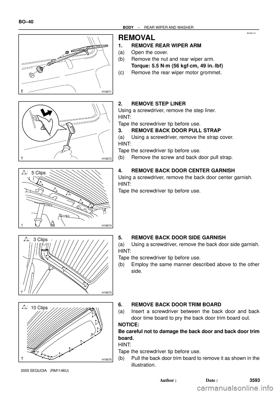
REMOVAL
1. REMOVE REAR WIPER ARM
(a) Open the cover.
(b) Remove the nut and rear wiper arm.
Torque: 5.5 N´m (56 kgf´cm, 49 in.´lbf)
(c) Remove the rear wiper motor grommet.
2. REMOVE STEP LINER
Using a screwdriver, remove the step liner.
HINT:
Tape the screwdriver tip before use.
3. REMOVE BACK DOOR PULL STRAP
(a) Using a screwdriver, remove the strap cover.
HINT:
Tape the screwdriver tip before use.
(b) Remove the screw and back door pull strap.
4. REMOVE BACK DOOR CENTER GARNISH
Using a screwdriver, remove the back door center garnish.
HINT:
Tape the screwdriver tip before use.
5. REMOVE BACK DOOR SIDE GARNISH
(a) Using a screwdriver, remove the back door side garnish.
HINT:
Tape the screwdriver tip before use.
(b) Employ the same manner described above to the other
side.
6. REMOVE BACK DOOR TRIM BOARD
(a) Insert a screwdriver between the back door and back
door time board to pry the back door trim board out.
NOTICE:
Be careful not to damage the back door and back door trim
board.
HINT:
Tape the screwdriver tip before use.
(b) Pull the back door trim board to remove it as shown in the
illustration.
Page 3606 of 4323
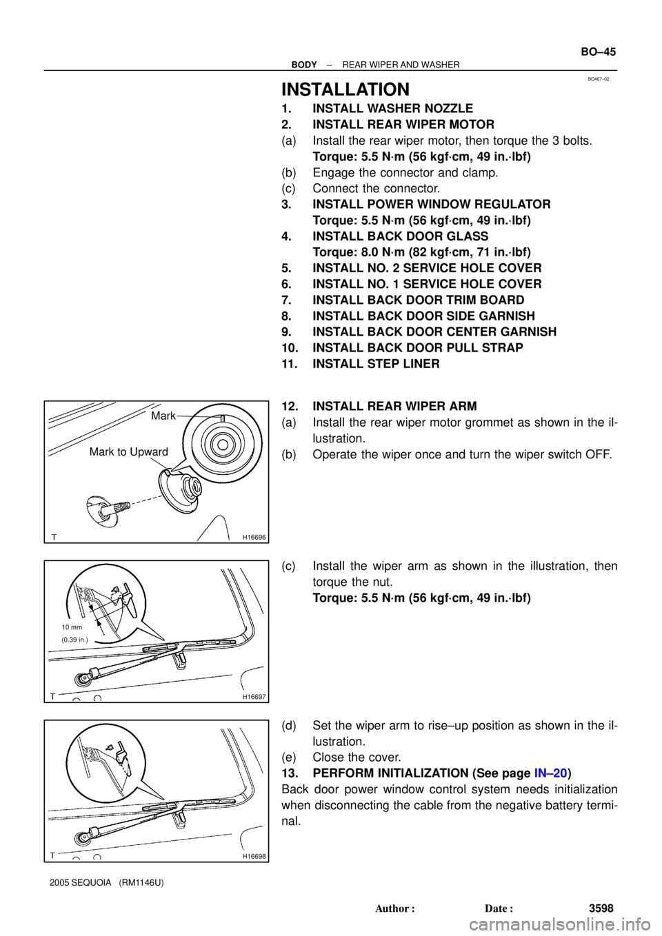
BO467±02
H16696
Mark
Mark to Upward
H16697
10 mm
(0.39 in.)
H16698
± BODYREAR WIPER AND WASHER
BO±45
3598 Author�: Date�:
2005 SEQUOIA (RM1146U)
INSTALLATION
1. INSTALL WASHER NOZZLE
2. INSTALL REAR WIPER MOTOR
(a) Install the rear wiper motor, then torque the 3 bolts.
Torque: 5.5 N´m (56 kgf´cm, 49 in.´lbf)
(b) Engage the connector and clamp.
(c) Connect the connector.
3. INSTALL POWER WINDOW REGULATOR
Torque: 5.5 N´m (56 kgf´cm, 49 in.´lbf)
4. INSTALL BACK DOOR GLASS
Torque: 8.0 N´m (82 kgf´cm, 71 in.´lbf)
5. INSTALL NO. 2 SERVICE HOLE COVER
6. INSTALL NO. 1 SERVICE HOLE COVER
7. INSTALL BACK DOOR TRIM BOARD
8. INSTALL BACK DOOR SIDE GARNISH
9. INSTALL BACK DOOR CENTER GARNISH
10. INSTALL BACK DOOR PULL STRAP
11. INSTALL STEP LINER
12. INSTALL REAR WIPER ARM
(a) Install the rear wiper motor grommet as shown in the il-
lustration.
(b) Operate the wiper once and turn the wiper switch OFF.
(c) Install the wiper arm as shown in the illustration, then
torque the nut.
Torque: 5.5 N´m (56 kgf´cm, 49 in.´lbf)
(d) Set the wiper arm to rise±up position as shown in the il-
lustration.
(e) Close the cover.
13. PERFORM INITIALIZATION (See page IN±20)
Back door power window control system needs initialization
when disconnecting the cable from the negative battery termi-
nal.