Page 2298 of 4323
HPR ± SGND
(H11±1 ± H11±3)
BR ± ShieldedSound signal (Input)External device sys")
I28322I28621
V10
DI±2096
± DIAGNOSTICSREAR SEAT ENTERTAINMANT SYSTEM
2290 Author�: Date�:
2005 SEQUOIA (RM1146U)HPR ± SGND
(H11±1 ± H11±3)
BR ± ShieldedSound signal (Input)External device system sounding
(At that time of VTR jack use)
A waveform
synchronized
with sound is
output
HPL ± SGND
(H11±2 ± H11±3)BR ± ShieldedSound signal (Input)External device system sounding
(At that time of VTR jack use)
A waveform
synchronized
with sound is
output
SGND ± Body ground
(H11±3 ± Body ground)Shielded ± Body groundGroundAlwaysBelow 1 V
5. VTR TERMINAL
Symbols (Terminals No.)Wiring ColorTerminal DescriptionConditionSpecification
AUXR ± GND
(V10±1 ± R23±29)BR ± YExternal audio R input
signalExternal device system sounding
(At that time of VTR jack use)
A waveform
synchronized
with sound is
output
AUXL ± GND
(V10±2 ± R23±29)BR ± YExternal audio L input
signalExternal device system sounding
(At that time of VTR jack use)
A waveform
synchronized
with sound is
output
SG6 ± Body ground
(V10±3 ± Body ground)Shielded ± Body groundGroundAlwaysBelow 1 V
CE ± GND
(V10±4 ± R23±29)LG ± YExternal VIDEO input
signalExternal device system sounding
(At that time of VTR jack use)
A waveform
synchronized
with sound is
output
NTS4 ± GND
(V10±5 ± R23±29)BR ± YDisplay signalVTR is displayedPulse genera-
tion
DGND ± Body ground
(V10±6 ± Body ground)BR ± Body groundGroundAlwaysBelow 1 V
SGN5 ± Body ground
(V10±7 ± Body ground)Shielded ± Body groundGroundAlwaysBelow 1 V
Page 2333 of 4323
I28666
Multi±display
Controller Sub±assy
R2112
R2111
R2110 BR
BR AUXR
AUXL
SG61
2
3
(Shielded) V10
VTR Terminal
AUXR
AUXL
SG7
± DIAGNOSTICSREAR SEAT ENTERTAINMANT SYSTEM
DI±2131
2325 Author�: Date�:
2005 SEQUOIA (RM1146U)
Sound signal circuit (Multi±display controller sub±assy ± VTR ter-
minal)
CIRCUIT DESCRIPTION
This is the sound signal circuit from the VTR terminal to the multi±display controller sub±assy.
WIRING DIAGRAM
DIDBF±01
Page 2334 of 4323
I28321I28327
VTR Terminal:
Multi±display Controller Sub±assy:SG6
V10
R21
AUXL
AUXR
AUXR
AUXL
SG7
DI±2132
± DIAGNOSTICSREAR SEAT ENTERTAINMANT SYSTEM
2326 Author�: Date�:
2005 SEQUOIA (RM1146U)
INSPECTION PROCEDURE
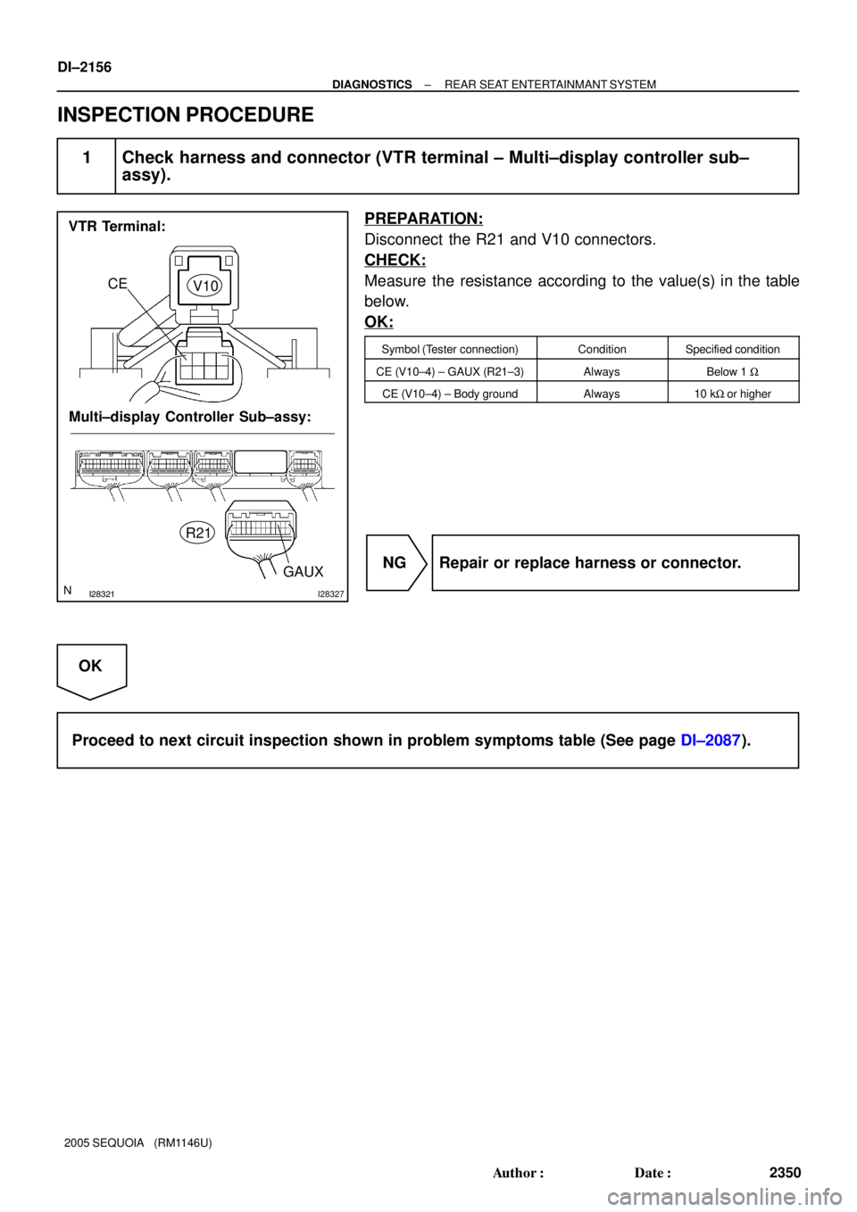
1 Check harness and connector (VTR terminal ± Multi±display controller sub±
assy).
PREPARATION:
Disconnect the R21 and V10 connectors.
CHECK:
Measure the resistance according to the value(s) in the table
below.
OK:
Symbol (Tester connection)ConditionSpecified condition
SG6 (V10±3) ± SG7 (R21±10)AlwaysBelow 1 W
AUXR (V10±1) ± AUXR (R21±12)AlwaysBelow 1 W
AUXL (V10±2) ± AUXL (R21±11)AlwaysBelow 1 W
AUXR (V10±1) ± Body groundAlways10 kW or higher
AUXL (V10±2) ± Body groundAlways10 kW or higher
SG6 (V10±3) ± Body groundAlways10 kW or higher
NG Repair or replace harness or connector.
OK
Proceed to next circuit inspection shown in problem symptoms table (See page DI±2087).
Page 2357 of 4323
I28495
Multi±display
Controller Sub±assy
LG3
GAUX R21
CE V10
VTR Terminal
4
± DIAGNOSTICSREAR SEAT ENTERTAINMANT SYSTEM
DI±2155
2349 Author�: Date�:
2005 SEQUOIA (RM1146U)
VTR terminal set signal circuit
CIRCUIT DESCRIPTION
When terminal GAUX is grounded, the multi±display controller recognizes that an external device is con-
nected.
WIRING DIAGRAM
DIDBM±01
Page 2358 of 4323
I28321I28327
VTR Terminal:
Multi±display Controller Sub±assy:
GAUX
CE
V10
R21
DI±2156
± DIAGNOSTICSREAR SEAT ENTERTAINMANT SYSTEM
2350 Author�: Date�:
2005 SEQUOIA (RM1146U)
INSPECTION PROCEDURE
1 Check harness and connector (VTR terminal ± Multi±display controller sub±
assy).
PREPARATION:
Disconnect the R21 and V10 connectors.
CHECK:
Measure the resistance according to the value(s) in the table
below.
OK:
Symbol (Tester connection)ConditionSpecified condition
CE (V10±4) ± GAUX (R21±3)AlwaysBelow 1 W
CE (V10±4) ± Body groundAlways10 kW or higher
NG Repair or replace harness or connector.
OK
Proceed to next circuit inspection shown in problem symptoms table (See page DI±2087).
Page 3861 of 4323
05_SEQUOIA_U (L/O 0408)
2
2005 SEQUOIA from Aug. '04 Prod. (OM34424U)
1. Side vents
2. Instrument cluster
3. Center vents
4. Multi±information display
5. Personal lights
6. Garage door opener box or auxiliary
box
7. Electric moon roof switches
8. Side defroster outlet
9. Glove box
10. Power door lock switches
11. Power window switches
12. Power outlets
13. Seat heater switches
14. Rear console box
15. Rear air conditioning controls
16. Headphone input jacks and headphone
volume control dials
17. Input terminal adapter
18. Cup holders
19. Power rear view mirror control switches
20. Lower vent
Instrument panel overview
�View A
Page 3895 of 4323

36
2005 SEQUOIA from Aug. 04 Prod. (OM34424U)
To open the hood:
1. Pull the hood lock release lever. The
hood will spring up slightly.
CAUTION
Before driving, be sure that the")
05_SEQUOIA_U (L/O 0408)
36
2005 SEQUOIA from Aug. '04 Prod. (OM34424U)
To open the hood:
1. Pull the hood lock release lever. The
hood will spring up slightly.
CAUTION
Before driving, be sure that the hood
is closed and securely locked. Other-
wise, the hood may open unexpected-
ly while driving and an accident may
occur.
2. In front of the vehicle, pull up the
auxiliary catch lever and lift the
hood.
Before closing the hood, check to see that
you have not forgotten any tools, rags,
etc. Then lower the hood make sure it
locks into place. If necessary, press down
gently on the front edge to lock it.To deter vehicle theft, the system is
designed to sound an alarm if any of
the side doors, back door or hood is
forcibly unlocked or opened or the bat-
tery terminal is disconnected and then
reconnected when the vehicle is locked.
On some models, the alarm also
sounds, when someone attempts to
break the side windows.
The alarm blows the horn intermittently
and flashes the headlights and tail lights.
HoodTheft deterrent system
Page 3915 of 4323

56
2005 SEQUOIA from Aug. 04 Prod. (OM34424U)
From front
From rear1. SEAT POSITION ADJUSTING LEVER
From frontÐ
Hold the center of the lever and pull it
up. Then slide the sea")
05_SEQUOIA_U (L/O 0408)
56
2005 SEQUOIA from Aug. '04 Prod. (OM34424U)
From front
From rear1. SEAT POSITION ADJUSTING LEVER
From frontÐ
Hold the center of the lever and pull it
up. Then slide the seat to the desired
position with slight body pressure and
release the lever.
From rearÐ
Pull the lever up. Then slide the seat
to the desired position and release the
lever.
When a person sits in the third seat
center position, adjust both seat cush-
ions to the same position.
Do not place anything under the seats. It
might interfere with the seat±lock mecha-
nism.
2. SEATBACK ANGLE ADJUSTING
LEVER
From frontÐ
Lean forward and pull the lever toward
you. Then lean back to the desired
angle and release the lever.
From rearÐ
Push down the lever. Push the seatback
forward or pull it backward to the de-
sired angle and release the lever.When a person sits in the third seat
center position, align both seatbacks at
the same angle.
Remove the center head restraint when
adjusting the seat position or seatback
angle.
Store the center head restraint in the aux-
iliary box on the rear left side panel when
it is not in use. (For details, see ªHead
restraintsº on page 66 in this Section.)
ÐAdjusting third seats


2
2005 SEQUOIA from Aug. 04 Prod. (OM34424U)
1. Side vents
2. Instrument cluster
3. Center vents
4. Multi±information display
5. Personal lights
6. Garage door opener box or")