Page 746 of 4323
D13545
Tester menu flow: DI±544
± DIAGNOSTICSAUTOMATIC TRANSMISSION
738 Author�: Date�:
2005 SEQUOIA (RM1146U)
NOTICE:
After performing the RESET MEMORY, be sure to perform the ROAD TEST (See page DI±535) de-
scribed earlier.
HINT:
The ECM learns through use of the ROAD TEST.
Page 766 of 4323
DI±564
± DIAGNOSTICSAUTOMATIC TRANSMISSION
758 Author�: Date�:
2005 SEQUOIA (RM1146U)
CHECK BATTERY VOLTAGE
Battery voltage: 11 to 14 V
If voltage is below 11 V, replace the battery before proceeding.
CHECK MIL
(a) Check that the MIL illuminates when turning the ignition
switch ON.
If the MIL does not illuminate, there is a problem in the MIL cir-
cuit (refer to MIL CIRCUIT on page DI±512)
(b) When the engine is started, the MIL should turn off.
ALL READINESS
For this vehicle, using the hand±held tester allows readiness
codes corresponding to all DTCs to be read. When diagnosis
(normal or malfunctioning) has been complete, readiness
codes are set. Enter the following menus: ENHANCED OBD II
/ MONITOR STATUS on the hand±held tester.
Page 767 of 4323

DIDJ0±01
D13872DLC3
OBD II Scan Tool
(Hand±held Tester)
CAN VIM
± DIAGNOSTICSAUTOMATIC TRANSMISSION
DI±565
759 Author�: Date�:
2005 SEQUOIA (RM1146U)
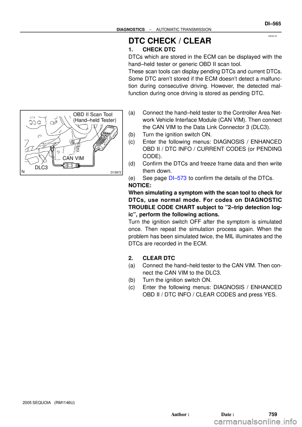
DTC CHECK / CLEAR
1. CHECK DTC
DTCs which are stored in the ECM can be displayed with the
hand±held tester or generic OBD II scan tool.
These scan tools can display pending DTCs and current DTCs.
Some DTC aren't stored if the ECM doesn't detect a malfunc-
tion during consecutive driving. However, the detected mal-
function during once driving is stored as pending DTC.
(a) Connect the hand±held tester to the Controller Area Net-
work Vehicle Interface Module (CAN VIM). Then connect
the CAN VIM to the Data Link Connector 3 (DLC3).
(b) Turn the ignition switch ON.
(c) Enter the following menus: DIAGNOSIS / ENHANCED
OBD II / DTC INFO / CURRENT CODES (or PENDING
CODE).
(d) Confirm the DTCs and freeze frame data and then write
them down.
(e) See page DI±573 to confirm the details of the DTCs.
NOTICE:
When simulating a symptom with the scan tool to check for
DTCs, use normal mode. For codes on DIAGNOSTIC
TROUBLE CODE CHART subject to º2±trip detection log-
icº, perform the following actions.
Turn the ignition switch OFF after the symptom is simulated
once. Then repeat the simulation process again. When the
problem has been simulated twice, the MIL illuminates and the
DTCs are recorded in the ECM.
2. CLEAR DTC
(a) Connect the hand±held tester to the CAN VIM. Then con-
nect the CAN VIM to the DLC3.
(b) Turn the ignition switch ON.
(c) Enter the following menus: DIAGNOSIS / ENHANCED
OBD II / DTC INFO / CLEAR CODES and press YES.
Page 768 of 4323

DIDJ1±01
D13872DLC3
OBD II Scan Tool
(Hand±held Tester)
CAN VIM
D14153
ON
OFF
0.13 seconds0.13 seconds DI±566
± DIAGNOSTICSAUTOMATIC TRANSMISSION
760 Author�: Date�:
2005 SEQUOIA (RM1146U)
CHECK MODE PROCEDURE
DESCRIPTION
Check mode has a higher sensitivity to malfunctions and can
detect malfunctions that normal mode cannot detect. Check
mode can also detect all the malfunctions that normal mode can
detect. In check mode, DTCs are detected with 1±trip detection
logic.
CHECK MODE PROCEDURE
(a) Make sure that the items below are true:
(1) Battery positive voltage 11 V or more
(2) Throttle valve fully closed
(3) Transmission in the P or N position
(4) A/C switched OFF
(b) Turn the ignition switch OFF.
(c) Connect the hand±held tester together with the Controller
Area Network Vehicle Interface Module (CAN VIM) to the
DLC3.
(d) Turn the ignition switch ON.
(e) Enter the following menus: DIAGNOSIS / ENHANCED
OBD II / CHECK MODE.
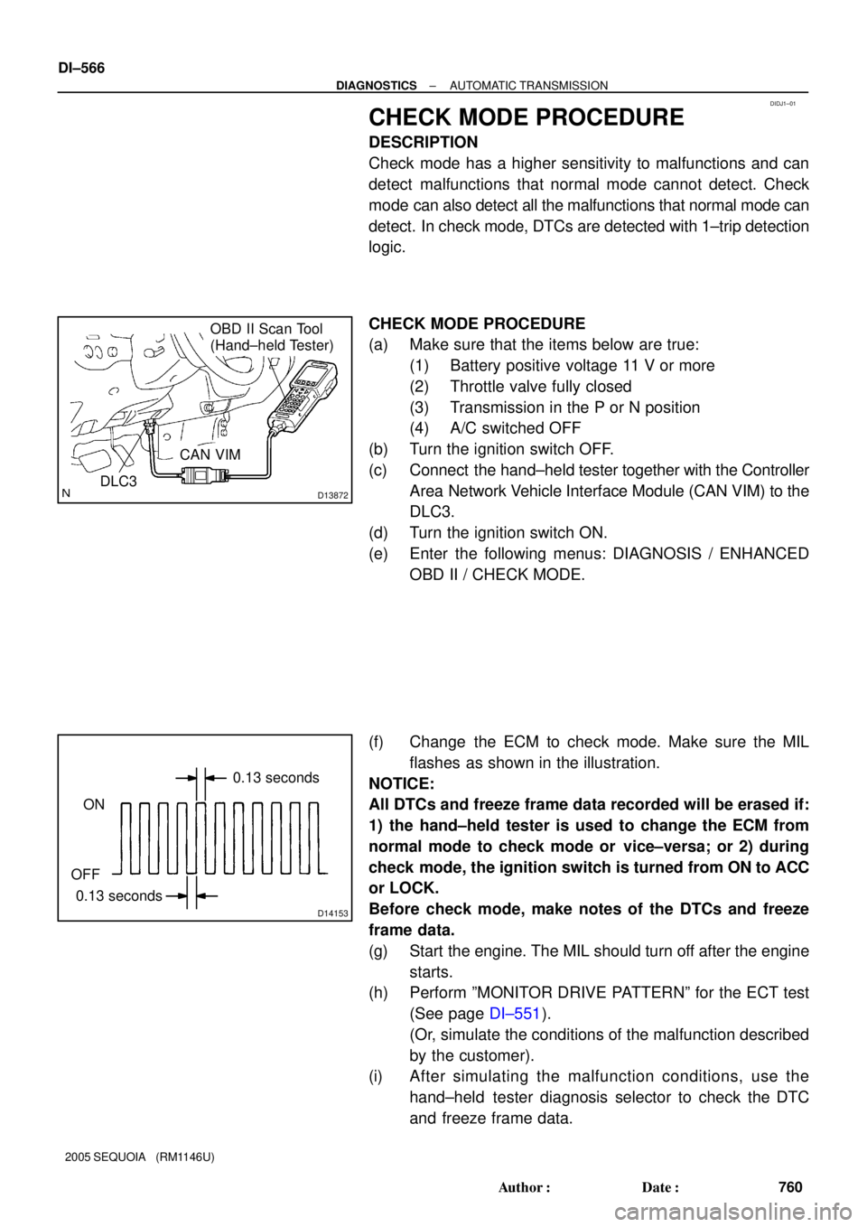
(f) Change the ECM to check mode. Make sure the MIL
flashes as shown in the illustration.
NOTICE:
All DTCs and freeze frame data recorded will be erased if:
1) the hand±held tester is used to change the ECM from
normal mode to check mode or vice±versa; or 2) during
check mode, the ignition switch is turned from ON to ACC
or LOCK.
Before check mode, make notes of the DTCs and freeze
frame data.
(g) Start the engine. The MIL should turn off after the engine
starts.
(h) Perform ºMONITOR DRIVE PATTERNº for the ECT test
(See page DI±551).
(Or, simulate the conditions of the malfunction described
by the customer).
(i) After simulating the malfunction conditions, use the
hand±held tester diagnosis selector to check the DTC
and freeze frame data.
Page 1275 of 4323
DIDI5±01
F19740
F19741
F19742
± DIAGNOSTICSCAN COMMUNICATION SYSTEM
DI±1073
1267 Author�: Date�:
2005 SEQUOIA (RM1146U)
DIAGNOSIS SYSTEM
1. BUS CHECK
HINT:
The ECUs that are properly connected to the CAN communica-
tion system can be displayed using the hand±held tester via
CAN VIM.
(a) Select ºBUS CHECKº from the ºOBD/MOBD MENUº
screen.
(b) Press ºENTERº on the hand±held tester via CAN VIM.
(c) The screen displays the ECUs and sensors that are prop-
erly connected to the CAN communication system.
HINT:
There is a communication stop in the system of any properly
connected ECUs or sensors that are not displayed
(see page DI±1067).
Page 1332 of 4323

DIAGNOSTIC MENU
OCCUPANT DETECT
1: DATA LIST
2: DTC INFO
5: ZERO CALIBRATION
6: SENSITIVITY CHK 4: SNAPSHOT
NOTICE
Please confirm seat
position.
Slide: Max rear
Recline: Max upright
Headrest: Max down
Lifter: Max down
PRESS [ENTER] or [EXIT]NOTICE
Confirm that
nothing is placed
on the passenger
seat.
PRESS [ENTER] or [EXIT]
NOTICE
Do you wish to
start ºZERO
CALIBRATIONº?
PRESS [YES] or [NO]ZERO CALIBRATION
COMPLETED
Next, perform the
SENSITIVITY CHECK.
PRESS [ENTER]
ZERO POINT CALIBRATION PROCEDURE
º1: DIAGNOSISº ± º1: OBD/MOBDº ± ºMODEL YEARº ± ºMODEL SELECTION = SEQUOIAº ±
Select the option parts ± º9: OCCUPANT DETECTº ± Refer to the following screen flow.
ZERO CALIBRATION
FAILED
EEPROM writing error
Please check DTCs
PRESS [ENTER]ZERO CALIBRATION
FAILED
Failed to SECURITY
ACCESS.
PRESS [ENTER]Try again
ZERO CALIBRATION
FAILED
Sensor range
Front Left
PRESS [ENTER] over malfunction
Front Right
Rear Left
Rear Right±±±±[ ]
±±±±[ ]
±±±±[ ]
±±±±[ ]Sensor information is
expressed as OK, MAX or MIN
in [ ].
If MAX or MIN is displayed,
replace the front seat assembly RH. Perform sensitivity check.
Perform DTC check and repair. DI±1130
± DIAGNOSTICSSUPPLEMENTAL RESTRAINT SYSTEM
1324 Author�: Date�:
2005 SEQUOIA (RM1146U)
Page 1333 of 4323
SENSITIVITY CHECK PROCEDURE
º1: DIAGNOSISº ± º1: OBD/MOBDº ± ºMODEL YEARº ± ºMODEL SELECTION = SEQUOIAº ±
Select the option parts ± º9: OCCUPANT DETECTº ± Refer to the following screen flow.
DIAGNOSTIC MENU
OCCUPANT DETECT
1: DATA LIST
2: DTC INFO
5: ZERO CALIBRATION
6: SENSITIVITY CHK 4: SNAPSHOT
NOTICE
Please confirm
that nothing is
placed on the
passenger seat.
PRESS [ENTER] or [EXIT]SENSITIVITY CHECK
Beginning sensor
reading should be
±3.2 to 3.2 kg.
PRESS [ENTER]
SENSITIVITY CHECK
PRESS [ENTER]
(±7 to 7 lbs)
Sensor reading
0.00 kg
Place 30 kg (66 lbs)
weight on passenger
seat. Sensor reading
should be 27 to 33 kg.
(59 to 73 lbs)
Sensor reading
0.00 kg*1: kg @ lb
Unit can be changed based on unit conversion setting.
[System Selection Screen]
º1: DIAGNOSISº ± º9: SETUPº ± º4: UNIT CONVERSIONº
± ºWEIGHTº (kg @ lbs) (*1)
± DIAGNOSTICSSUPPLEMENTAL RESTRAINT SYSTEM
DI±1131
1325 Author�: Date�:
2005 SEQUOIA (RM1146U)
Page 2287 of 4323
DIDAY±01
I28281
ºDiagnosis MENUº
to section
Press ENTER on
remote control
The entire screen is changed
to the color which is selected
in the color bar check mode. Select color by
remote control
operation
± DIAGNOSTICSREAR SEAT ENTERTAINMANT SYSTEM
DI±2085
2279 Author�: Date�:
2005 SEQUOIA (RM1146U)
DISPLAY CHECK MODE
DISPLAY CHECK MODE
HINT:
�Illustrations may differ from the actual vehicle depending on the device settings and options. There-
fore, some detailed areas may not be shown exactly the same as on the actual vehicle.
�Display check mode is operated as follows.