Page 682 of 4323
B02272
Battery
Air
B17440
Wire Harness Side:
Purge VSV Connector
V4
Front View
DI±480
± DIAGNOSTICSENGINE
674 Author�: Date�:
2005 SEQUOIA (RM1146U)
16 Inspect EVAP VSV.
PREPARATION:
(a) Remove the purge VSV.
(b) Apply battery voltage to the terminals of the purge VSV.
CHECK:
Using an air gun, confirm that air flows from port A to port B.
RESULT:
Test ResultsSuspected Trouble AreasProceed To
Suction appliedEVAP hose between purge VSV and throttle body
normalA
No suction
�Throttle body
�EVAP hose between purge VSV and throttle
body
B
B Go to step 31.
A
17 Measure purge VSV terminal voltage.
PREPARATION:
(a) Disconnect the V4 purge VSV connector.
(b) Turn the ignition switch to ON.
CHECK:
(a) Measure the voltage between terminal 1 of the purge VSV
connector and the body ground.
RESULT:
Test ResultsSuspected Trouble AreasProceed To
Between 11 V and 14 VNormalA
Other than result aboveWire harness or connectors between purge VSV
and ECMB
B Go to step 32.
A
Page 686 of 4323

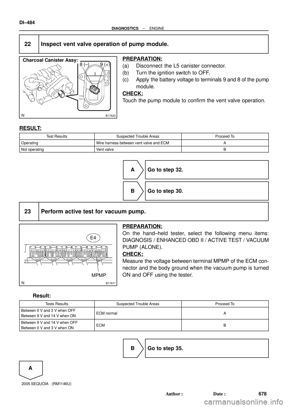
B17423
8 (±) 9 (+)Charcoal Canister Assy:
B17411
MPMP
E4
DI±484
± DIAGNOSTICSENGINE
678 Author�: Date�:
2005 SEQUOIA (RM1146U)
22 Inspect vent valve operation of pump module.
PREPARATION:
(a) Disconnect the L5 canister connector.
(b) Turn the ignition switch to OFF.
(c) Apply the battery voltage to terminals 9 and 8 of the pump
module.
CHECK:
Touch the pump module to confirm the vent valve operation.
RESULT:
Test ResultsSuspected Trouble AreasProceed To
OperatingWire harness between vent valve and ECMA
Not operatingVent valveB
A Go to step 32.
B Go to step 30.
23 Perform active test for vacuum pump.
PREPARATION:
On the hand±held tester, select the following menu items:
DIAGNOSIS / ENHANCED OBD II / ACTIVE TEST / VACUUM
PUMP (ALONE).
CHECK:
Measure the voltage between terminal MPMP of the ECM con-
nector and the body ground when the vacuum pump is turned
ON and OFF using the tester.
Result:
Tests ResultsSuspected Trouble AreasProceed To
Between 0 V and 3 V when OFF
Between 9 V and 14 V when ONECM normalA
Between 9 V and 14 V when OFF
Between 0 V and 3 V when ONECMB
B Go to step 35.
A
Page 695 of 4323
± DIAGNOSTICSENGINE
DI±493
687 Author�: Date�:
2005 SEQUOIA (RM1146U)
ECM Power Source Circuit
CIRCUIT DESCRIPTION
When the ignition switch is turned ON, battery positive voltage is applied to terminal IGSW of the ECM and
the EFI relay control circuit in the ECM sends a signal to terminal MREL of the ECM switching on the EFI
relay.
This signal causes current to flow to the coil, closing the contacts of the EFI relay and supplying power to
terminal +B of the ECM.
DID8K±01
Page 696 of 4323
A23555
F10
Fusible
Link
Block9
+B
BatteryE1 1
8
1 E4
E6
BR 4D
B±R
67 I18 Ignition SW 2
W±R 1C 1E
1C2
13
BIG2
IA4
B±WECM
Engine Room J/B
EFI Relay
1DIGSW
MREL E4E4 17 IGN1
4E
Instrument Panel J/BSub J/B No. 4
5
AM2 Instrument Panel J/B
1
16 AM21J
2D
2F2C
2H 5
32
IA4J/C
5 4
B14 12 2
J16
A
EB EDD
J5
J/C W±B2H
2B±R
B±WB±R B±R EFI No. 1W±RB±O
B±O DI±494
± DIAGNOSTICSENGINE
688 Author�: Date�:
2005 SEQUOIA (RM1146U)
WIRING DIAGRAM
Page 702 of 4323
A14809
B
BW
WB 2
EB2V2
VSV (ACIS)
2 1L±W21
E4ECM
ACIS
MREL 13
E3 P±B
B±R 1
1
1
1 1 1 1 1
12 EFI No. 2
EFI Main Relay
21
3
5
EFI No. 1
12
Engine Room No. 1 R/B
B±L
Battery B±W
W±B J3
J/C
AA
D
D
W±B
ECW
FL MAIN
1
1
4B
4A
FL BLOCK J7
J/C
W±B
1A DI±500
± DIAGNOSTICSENGINE
694 Author�: Date�:
2005 SEQUOIA (RM1146U)
WIRING DIAGRAM
Page 705 of 4323

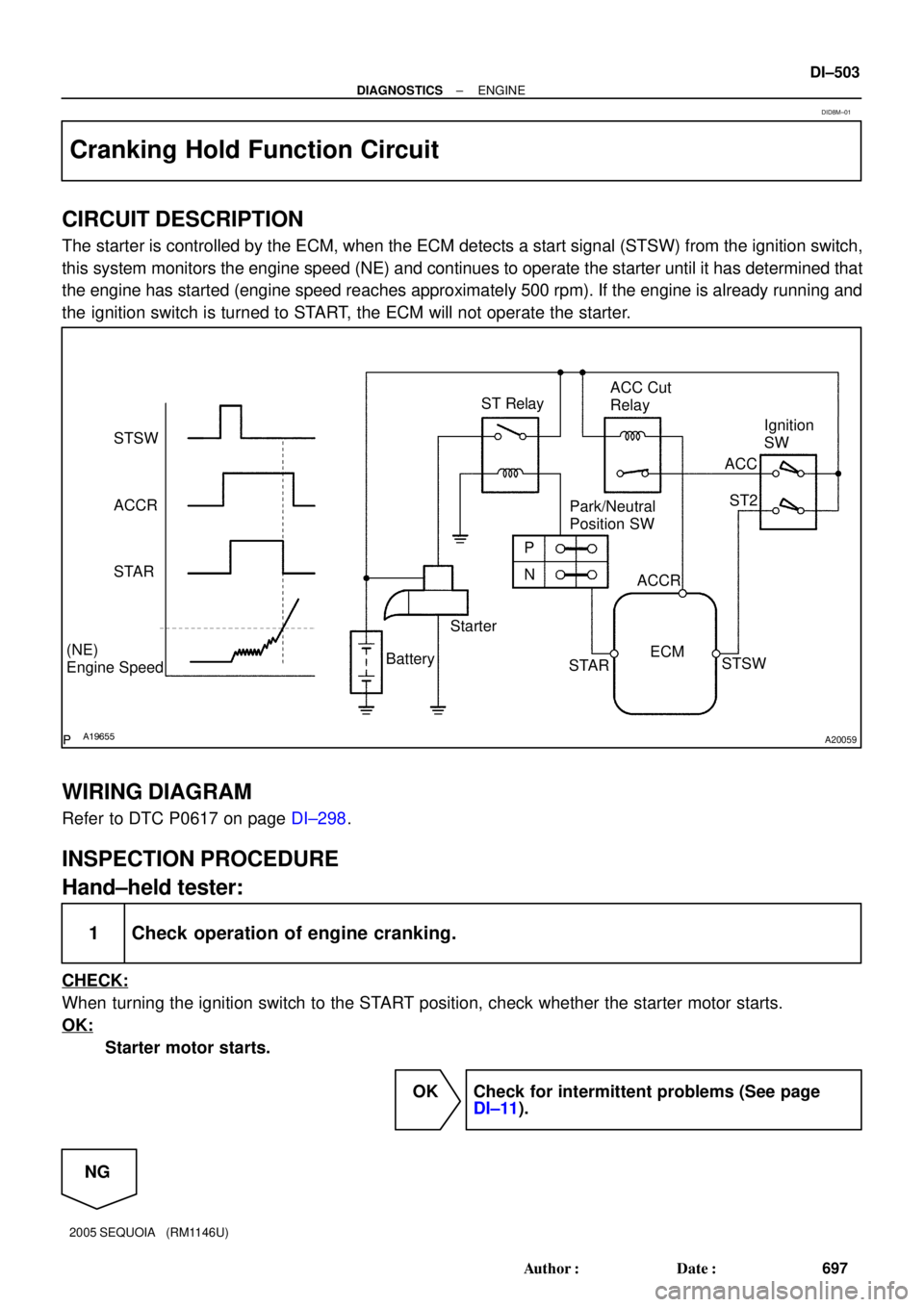
A19655A20059
STSW
ACCR
STAR
(NE)
Engine SpeedStarterPark/Neutral
Position SW
N P ST RelayACC Cut
Relay
Ignition
SW
ACC
ST2
ACCR
STSW
STAR BatteryECM
± DIAGNOSTICSENGINE
DI±503
697 Author�: Date�:
2005 SEQUOIA (RM1146U)
Cranking Hold Function Circuit
CIRCUIT DESCRIPTION
The starter is controlled by the ECM, when the ECM detects a start signal (STSW) from the ignition switch,
this system monitors the engine speed (NE) and continues to operate the starter until it has determined that
the engine has started (engine speed reaches approximately 500 rpm). If the engine is already running and
the ignition switch is turned to START, the ECM will not operate the starter.
WIRING DIAGRAM
Refer to DTC P0617 on page DI±298.
INSPECTION PROCEDURE
Hand±held tester:
1 Check operation of engine cranking.
CHECK:
When turning the ignition switch to the START position, check whether the starter motor starts.
OK:
Starter motor starts.
OK Check for intermittent problems (See page
DI±11).
NG
DID8M±01
Page 707 of 4323
D14154
Component Side:
A19288
± DIAGNOSTICSENGINE
DI±505
699 Author�: Date�:
2005 SEQUOIA (RM1146U)
4 Check park/neutral position switch.
PREPARATION:
Remove the P1 park/neutral position switch connector.
CHECK:
Check resistance between each terminal shown below when
the shift lever is moved to each range.
Shift rangeTerminal No. to continuity
P1 ± 36 ± 9
R2 ± 3±
N3 ± 56 ± 9
D3 ± 7±
23 ± 4±
L3 ± 8±
OK:
Below 1 W
NG Replace the park/neutral position switch.
OK
Check and repair harness and connector be-
tween park/neutral position switch and ECM.
5 Check starter relay.
(a) Remove the starter relay from the engine room R/B.
(b) Inspect the starter relay.
Standard:
Tester ConnectionSpecified Condition
3 ± 510 kW or higher
3 ± 5Below 1 W
(Apply battery voltage to terminals 1 and 2)
NG Replace starter relay.
OK
Page 709 of 4323
A21559
Engine Room R/B No.2
Starter Relay
± DIAGNOSTICSENGINE
DI±507
701 Author�: Date�:
2005 SEQUOIA (RM1146U)
7 Check engine room R/B No.2 (Starter relay voltage).
PREPARATION:
Remove the starter relay from the engine room R/B No.2.
CHECK:
Measure the voltage between the terminal of the engine room
R/B and body ground.
OK:
Standard:
Tester ConnectionSpecified Condition
Starter relay (5) ± Body ground9 to 14 V
NG Check and repair harness and connector be-
tween starter relay and battery.
OK
8 Check starter (See page ST±15).
NG Repair or replace starter.
OK