Page 931 of 4323

DIAGNOSTIC TROUBLE CODE CHART
HINT:
�Inspect the fuse before inspecting the suspected areas as shown")
DIDDG±01
± DIAGNOSTICSAIR SUSPENSION SYSTEM
DI±729
923 Author�: Date�:
2005 SEQUOIA (RM1146U)
DIAGNOSTIC TROUBLE CODE CHART
HINT:
�Inspect the fuse before inspecting the suspected areas as shown in the chart below.
�If no abnormality is found when the parts are inspected, inspect the suspension control ECU.
�If a trouble code is displayed during the DTC check, check the circuit listed for that code. For details
of each code, refer to the ºSee pageº under respective DTC No. in the DTC chart.
DTC No.
(See Page)Detection ItemTrouble Area
Manual
Indicator
Lamp*
1Memory*2
C1714/14
(DI±731)Open or short in left rear height
control sensor circuit�Height control sensor sub±assy
�Height control sensor circuit
�Suspension control ECU
��
C1733/33
(DI±736)Open or short in gate solenoid
valve circuit�Gate solenoid valve (Height control valve)
�Gate solenoid valve (Height control valve) circuit
�Suspension control ECU
��
C1734/34
(DI±740)Open or short in leveling sole-
noid valve circuit�Leveling solenoid valve (Height control valve)
�Leveling solenoid valve (Height control valve) circuit
�Suspension control ECU
��
C1735/35
(DI±744)Open or short in exhaust sole-
noid valve circuit�Exhaust solenoid valve (Height control compressor)
�Exhaust solenoid valve (Height control compressor) circuit
�Suspension control ECU
��
C1741/41
(DI±747)Open or short in AIR SUS relay
circuit�AIR SUS relay
�AIR SUS relay circuit
�Suspension control ECU
��
C1742/42
(DI±752)Lock, open or short in height
control compressor circuit�Height control compressor assy
�Height control compressor circuit
�Suspension control ECU
��
C1751/51*3
(DI±757)
Continuous electric current to
height control compressor circuit
�Height control compressor assy
�Height control compressor circuit
�Height control sensor circuit
�Height control sensor sub±assy
�Relief valve
�AIR SUS relay circuit
�Air leakage from the air tube or each valve
�Clogging in the air tube or each valve
�Suspension control ECU
X�
C1761/61
(DI±761)ECU malfunction
�Power source circuit
�Suspension control ECU
�Communication circuit
� / X�
C1774/74
(DI±763)Power source drop
�Battery
�Power source circuit
�Suspension control ECU
XX
U0100/65
(DI±782)Lost communication with ECM/
PCM�ECM
�Suspension control ECU
�Communication circuit
XX
U0122/67
(DI±783)Lost communication with TL
ECU�Translate ECU
�Suspension control ECU
�Communication circuit
XX
U0132/71
(DI±784)Lost communication with ride
level control module�Suspension control ECU
�Communication circuitXX
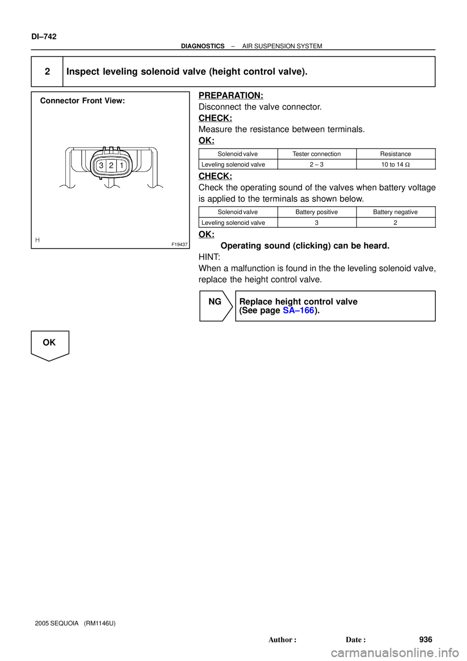
Page 940 of 4323
F19437
Connector Front View:
32 1
DI±738
± DIAGNOSTICSAIR SUSPENSION SYSTEM
932 Author�: Date�:
2005 SEQUOIA (RM1146U)
2 Inspect gate solenoid valve (height control valve).
PREPARATION:
Disconnect the valve connector.
CHECK:
Measure the resistance between terminals.
OK:
Solenoid valveTester connectionResistance
Gate solenoid valve1 ± 217.5 to 21.5 W
CHECK:
Check the operating sound of the valves when battery voltage
is applied to the terminals as shown below.
Solenoid valveBattery positiveBattery negative
Gate solenoid valve12
OK:
Operating sound (clicking) can be heard.
HINT:
When a malfunction is found in the gate solenoid valve, replace
the height control valve.
NG Replace height control valve
(See page SA±166).
OK
Page 944 of 4323
F19437
Connector Front View:
32 1
DI±742
± DIAGNOSTICSAIR SUSPENSION SYSTEM
936 Author�: Date�:
2005 SEQUOIA (RM1146U)
2 Inspect leveling solenoid valve (height control valve).
PREPARATION:
Disconnect the valve connector.
CHECK:
Measure the resistance between terminals.
OK:
Solenoid valveTester connectionResistance
Leveling solenoid valve2 ± 310 to 14 W
CHECK:
Check the operating sound of the valves when battery voltage
is applied to the terminals as shown below.
Solenoid valveBattery positiveBattery negative
Leveling solenoid valve32
OK:
Operating sound (clicking) can be heard.
HINT:
When a malfunction is found in the the leveling solenoid valve,
replace the height control valve.
NG Replace height control valve
(See page SA±166).
OK
Page 947 of 4323

INSPECTION PROCEDURE
HINT:
�If DTC C1761/61 (ECU malfunction) and/or C1774/74 (pow")
F19457
Connector Front View:
± DIAGNOSTICSAIR SUSPENSION SYSTEM
DI±745
939 Author�: Date�:
2005 SEQUOIA (RM1146U)
INSPECTION PROCEDURE
HINT:
�If DTC C1761/61 (ECU malfunction) and/or C1774/74 (power source circuit) is displayed, perform the
inspection necessary for DTC C1761/61 (See page DI±761) and/or C1774/74 (See page DI±763) first.
(If DTC C1761/61 and the C1774/74 are output at the same time, perform the inspection necessary
for DTC C1774/74 first.)
1 Inspect exhaust solenoid valve (height control compressor).
PREPARATION:
Disconnect the valve connector.
CHECK:
Measure the resistance between terminals.
OK:
Solenoid valveTester connectionResistance
Exhaust solenoid valve1 ± 210 to 14 W
CHECK:
Check the operating sound of the valves when battery voltage
is applied to the terminals as shown below.
Solenoid valveBattery positiveBattery negative
Exhaust solenoid valve12
OK:
Operating sound (clicking) can be heard.
HINT:
When a malfunction is found in the exhaust solenoid valve, re-
place the height control compressor.
NG Replace height control compressor assy
(See page SA±162).
OK
Page 949 of 4323

DTC C1741/41 Air Sus Relay Circuit
CIRCUIT DESCRIPTION
When the ºUPº side of the height control switch is pre")
± DIAGNOSTICSAIR SUSPENSION SYSTEM
DI±747
941 Author�: Date�:
2005 SEQUOIA (RM1146U)
DTC C1741/41 Air Sus Relay Circuit
CIRCUIT DESCRIPTION
When the ºUPº side of the height control switch is pressed, a signal is sent from terminal RC of the suspen-
sion control ECU to the AIR SUS relay to turn it on.
As a result, the current flows to the AIR SUS relay coil, closing the relay contact, and then the battery positive
voltage is applied to the compressor, which causes the compressed air to raise the vehicle height.
DTC No.DTC Detecting ConditionTrouble Area
C1741/41
Either of the following conditions is detected:
1. With the AIR SUS relay inactivated, an open signal of the
AIR SUS relay is detected for 1 sec. or more.
2. With the AIR SUS relay activated, a short signal of the AIR
SUS relay is detected 8 times successively.
�AIR SUS relay
�AIR SUS relay circuit
�Suspension control ECU
HINT:
Once the ECU stores DTC C1741/41 in the memory, the vehicle height control is suspended until a normal
signal is input to the ECU from the AIR SUS relay. However, the control resumes if the ignition switch is turned
OFF, and then turned ON again.
DIDDT±01
Page 950 of 4323
F19443
Height Control
Compressor
H131
Engine Room R/B No. 2
G±Y AIR SUS Relay
Battery J28
J/C W
BM21
IC48
IA121
WWW
2
22
2 3
25
1W
9B
5
W±B
J8
J/C
AAW±B
1K12
1F9
A W±B
IESuspension
Control
ECU
IA125
G±Y
S255
RC F10
Fusible Link Block
ALT
Instrument
Panel J/BAIR SUS DI±748
± DIAGNOSTICSAIR SUSPENSION SYSTEM
942 Author�: Date�:
2005 SEQUOIA (RM1146U)
WIRING DIAGRAM
Page 952 of 4323
F19458
DI±750
± DIAGNOSTICSAIR SUSPENSION SYSTEM
944 Author�: Date�:
2005 SEQUOIA (RM1146U)
2 Inspect AIR SUS relay.
PREPARATION:
Remove the AIR SUS relay from the engine room R/B No. 2.
CHECK:
Check continuity between each terminal of the AIR SUS relay.
OK:
Tester connectionResistance
3 ± 510 kW or higher
3 ± 5
Below 1 W
(When battery voltage is applied to ter-
minals 1±2)
NG Replace AIR SUS relay.
OK
Page 955 of 4323
F19444
Height Control Compressor
(Compressor/Height Control Dryer)
H133
Engine Room R/B No. 2
W±B
Battery J28
J/CR±L
BM23
IN115
S2520
2
3
25
1W
9B
5
J8
J/C
AAW±B
1K12
1F9
A W±B
IESuspension
Control
ECU
RC F10
Fusible Link Block
AIR SUS
Instrument
Panel J/BRM+ R±L R±L
H134
BR±Y
BM24
IA121S2521
BR±Y BR±Y
RM±
AIR SUS Relay H131
W
BM21
IC48
WW W
22
2 S255
G±Y IN16
IA125
G±Y
BJ H132
BM22
W±B
AJ19
J/C W±BALT
± DIAGNOSTICSAIR SUSPENSION SYSTEM
DI±753
947 Author�: Date�:
2005 SEQUOIA (RM1146U)
WIRING DIAGRAM


H133
Engine Room R/B No. 2
W±B
Battery J28
J/CR±L
BM23
IN115
S2520
2
3
25
1W
9B
5
J8
J/C
AAW±B
1K12
1F9
A W±B
IESuspension
Contro")