Page 1072 of 4323
F19792
Combination Meter
Tire Pressure Monitor ECU
To BatterySPD G±O3
T17 C520
IEInstrument Panel J/BG±O
J8
J/C
AIF 10
1
1H11
T17GND
IG W±B W±B
T17 J17
J/C
BB
2 DI±870
± DIAGNOSTICSTIRE PRESSURE WARNING SYSTEM
1064 Author�: Date�:
2005 SEQUOIA (RM1146U)
DTC C2191/91 Vehicle Speed Signal Error
CIRCUIT DESCRIPTION
The tire pressure monitor ECU receives a speed signal from the combination meter. This DTC is stored upon
entering test mode but erased when a vehicle speed signal of 12 mph (20 km/h) is detected for 3 seconds
or more. The DTC is output only in test mode.
DTC No.DTC Detecting ConditionTrouble Area
C2191/91Speed sensor circuit malfunction.
�Vehicle speed sensor
�Combination meter assy
�Tire pressure monitor ECU
�Wire harness
WIRING DIAGRAM
DIDKE±01
Page 1075 of 4323
F19174
Combination MeterTire Pressure
Monitor ECU
Engine Room J/B I18
Ignition SW IGN1
B±O
IG2 AM2 1C11
Battery 2
1H
T17 C5GR±L
Tire Pressure
B±R
B 56
54AM2 24
6IND Instrument Panel J/B
C620
2D1
2C1 1C3
1J7
F10
Fusible Link BlockInstrument Panel J/B
W±R
W±R
B
± DIAGNOSTICSTIRE PRESSURE WARNING SYSTEM
DI±873
1067 Author�: Date�:
2005 SEQUOIA (RM1146U)
Tire Pressure Warning Lamp Circuit
CIRCUIT DESCRIPTION
If the ECU detects trouble, the tire pressure warning lamp comes on and tire pressure monitor is cancelled
at the same time. At this time, the ECU records a DTC in memory.
Connect terminals Tc and CG of the DLC3 to make the tire pressure warning lamp blink and output the DTC.
WIRING DIAGRAM
DIDKF±01
Page 1077 of 4323
F19790
Combination MeterTire Pressure
Monitor ECU
Engine Room J/B I18
Ignition SWIGN1
B±O
IG2AM2 1C11
Battery 2
1HT17
C5GR±L
Tire Pressure
B±R
B 56
54AM2 24
6IND Instrument Panel J/B
C620
2D1
2C1 1C3
1J7
F10
Fusible Link BlockInstrument Panel J/B
W±R
W±R
B
T17 T18 Tire Pressure
Warning Reset SW
G±R
CALSW
GND
T17 1H
1H
1F7
1 10
W±B11 10 Instrument Panel J/B
W±B
A J8
J/C
IE1 2
± DIAGNOSTICSTIRE PRESSURE WARNING SYSTEM
DI±875
1069 Author�: Date�:
2005 SEQUOIA (RM1146U)
Tire Pressure Warning Reset Switch Circuit
CIRCUIT DESCRIPTION
Receiving the signal from the tire pressure warning reset switch, the tire pressure monitor ECU indicates the
initialization of the pressure warning system.
WIRING DIAGRAM
DIDKG±01
Page 1080 of 4323
F19175
Tire Pressure
Monitor ECU
IG
GND T17
11 B±R
I18
Ignition SW
2
AM1
8 W
BatteryT172 8
3C
A
A J37
J/C
B±R
IG11 ECU±IG B±R
B±Y
1
52 AM1
ALT
BW±B
A
J8
J/C W±BW±L
F10
Fusible Link BlockInstrument Panel J/B8
3A
4
1F4
1C
1
1L6
1C Instrument Panel J/B
IE10
1F1
1H Instrument Panel J/B Sub J/B No. 3 DI±878
± DIAGNOSTICSTIRE PRESSURE WARNING SYSTEM
1072 Author�: Date�:
2005 SEQUOIA (RM1146U)
ECU Power Source Circuit
CIRCUIT DESCRIPTION
This is the power source for the tire pressure monitor ECU. It also supplies power to the tire pressure monitor
receiver via the ECU.
WIRING DIAGRAM
DIDKH±01
Page 1081 of 4323
F13970
ECU±IG Instrument
Panel J/B:
± DIAGNOSTICSTIRE PRESSURE WARNING SYSTEM
DI±879
1073 Author�: Date�:
2005 SEQUOIA (RM1146U)
INSPECTION PROCEDURE
NOTICE:
It is necessary to register an ID code after replacing the tire pressure monitor valve sub±assy and/or
the tire pressure monitor ECU (see page DI±805).
1 Inspect battery.
CHECK:
Check the battery voltage.
OK:
Voltage: 11 to 14 V
NG Check and repair charging system.
(See page CH±1)
OK
2 Inspect fuse (ECU±IG).
PREPARATION:
Remove the ECU±IG fuse from the instrument panel J/B.
CHECK:
Check continuity of the ECU±IG fuse.
OK:
Continuity
NG Check for a short in all harness and connector
connected to fuse and replace fuse.
OK
Page 1093 of 4323

DIDLU±01
± DIAGNOSTICSABS WITH EBD & BA & TRAC & VSC SYSTEM
DI±891
1085 Author�: Date�:
2005 SEQUOIA (RM1146U)
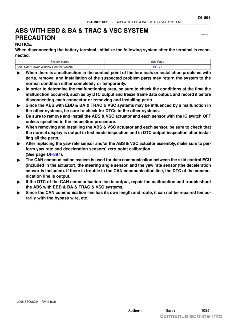
ABS WITH EBD & BA & TRAC & VSC SYSTEM
PRECAUTION
NOTICE:
When disconnecting the battery terminal, initialize the following system after the terminal is recon-
nected.
System NameSee Page
Back Door Power Window Control SystemBE±77
�When there is a malfunction in the contact point of the terminals or installation problems with
parts, removal and installation of the suspected problem parts may return the system to the
normal condition either completely or temporarily.
�In order to determine the malfunctioning area, be sure to check the conditions at the time the
malfunction occurred, such as by DTC output and freeze frame data output, and record it before
disconnecting each connector or removing and installing parts.
�Since the ABS with EBD & BA & TRAC & VSC systems may be influenced by a malfunction in
the other systems, be sure to check for DTCs in the other systems.
�Be sure to remove and install the ABS & VSC actuator and each sensor with the IG switch OFF
unless specified in the inspection procedure.
�When removing and installing the ABS & VSC actuator and each sensor, be sure to check that
the normal display is output in test mode inspection and in DTC output inspection after instal-
ling all the parts.
�After replacing the yaw rate sensor and/or the ABS & VSC actuator assembly, make sure to per-
form yaw rate and deceleration sensors' zero point calibration
(See page DI±897).
�The CAN communication system is used for data communication between the skid control ECU
(included in the actuator), the steering angle sensor, and the yaw rate sensor (the deceleration
sensor is included). If there is trouble in the CAN communication line, the DTC of the commu-
nication line is output.
�If the DTC of the CAN communication line is output, repair the malfunction and troubleshoot
the ABS with EBD & BA & TRAC & VSC systems.
�Since the CAN communication line has its own length and route, it can not be repaired tempo-
rarily with the bypass wire, etc.
Page 1115 of 4323
F09750
CG TcDLC3
BR3890
D05981
Hand±held
Tester
DLC3
± DIAGNOSTICSABS WITH EBD & BA & TRAC & VSC SYSTEM
DI±913
1107 Author�: Date�:
2005 SEQUOIA (RM1146U)
USING SST (CHECK WIRE):
4. CLEAR DTC
(a) Using SST, connect terminals Tc and CG of the DLC3.
SST 09843±18040
(b) Turn the ignition switch to the ON position.
(c) Clear the DTC stored in the ECU by depressing the brake
pedal 8 times or more within 5 seconds.
(d) Check that the warning light indicates the normal code.
(e) Remove the SST from the terminals of the DLC3.
SST 09843±18040
HINT:
Cancellation cannot be done by removing the battery cable or
ECU±IG fuse.
USING HAND±HELD TESTER:
5. CLEAR DTC
(a) Hook up the hand±held tester to the DLC3.
(b) Turn the ignition switch to the ON position.
(c) Operate the hand±held tester to erase the codes.
HINT:
(d) Please refer to the hand±held tester operator's manual
for further details.
Page 1123 of 4323

DI93C±06
± DIAGNOSTICSABS WITH EBD & BA & TRAC & VSC SYSTEM
DI±921
111 5 Author�: Date�:
2005 SEQUOIA (RM1146U)
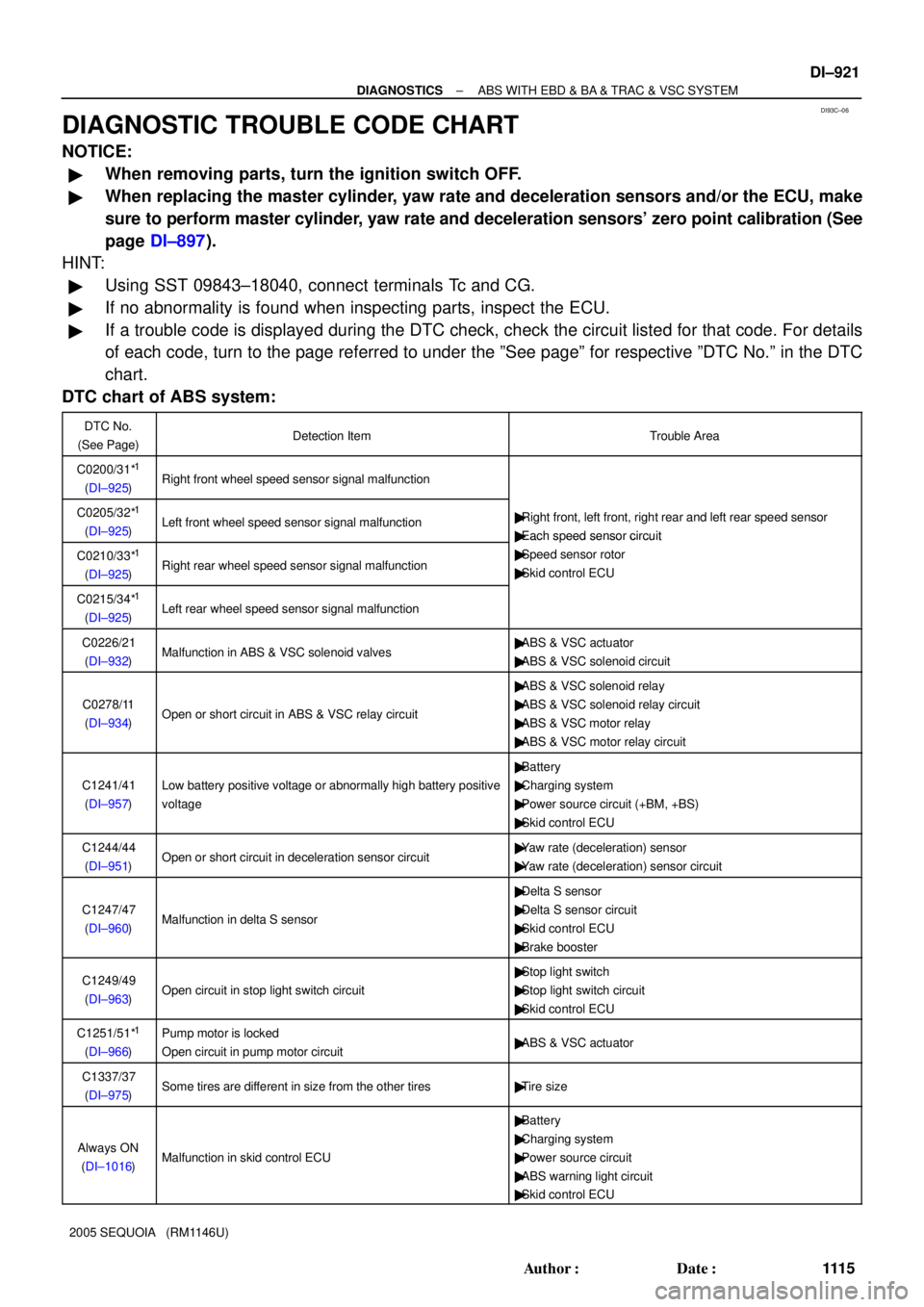
DIAGNOSTIC TROUBLE CODE CHART
NOTICE:
�When removing parts, turn the ignition switch OFF.
�When replacing the master cylinder, yaw rate and deceleration sensors and/or the ECU, make
sure to perform master cylinder, yaw rate and deceleration sensors' zero point calibration (See
page DI±897).
HINT:
�Using SST 09843±18040, connect terminals Tc and CG.
�If no abnormality is found when inspecting parts, inspect the ECU.
�If a trouble code is displayed during the DTC check, check the circuit listed for that code. For details
of each code, turn to the page referred to under the ºSee pageº for respective ºDTC No.º in the DTC
chart.
DTC chart of ABS system:
DTC No.
(See Page)Detection ItemTrouble Area
C0200/31*1
(DI±925)Right front wheel speed sensor signal malfunction
C0205/32*1
(DI±925)Left front wheel speed sensor signal malfunction�Right front, left front, right rear and left rear speed sensor
�Each speed sensor circuit
C0210/33*1
(DI±925)Right rear wheel speed sensor signal malfunction
�Each s eed sensor circuit
�Speed sensor rotor
�Skid control ECU
C0215/34*1
(DI±925)Left rear wheel speed sensor signal malfunction
C0226/21
(DI±932)Malfunction in ABS & VSC solenoid valves�ABS & VSC actuator
�ABS & VSC solenoid circuit
C0278/11
(DI±934)Open or short circuit in ABS & VSC relay circuit
�ABS & VSC solenoid relay
�ABS & VSC solenoid relay circuit
�ABS & VSC motor relay
�ABS & VSC motor relay circuit
C1241/41
(DI±957)Low battery positive voltage or abnormally high battery positive
voltage
�Battery
�Charging system
�Power source circuit (+BM, +BS)
�Skid control ECU
C1244/44
(DI±951)Open or short circuit in deceleration sensor circuit�Yaw rate (deceleration) sensor
�Yaw rate (deceleration) sensor circuit
C1247/47
(DI±960)Malfunction in delta S sensor
�Delta S sensor
�Delta S sensor circuit
�Skid control ECU
�Brake booster
C1249/49
(DI±963)Open circuit in stop light switch circuit
�Stop light switch
�Stop light switch circuit
�Skid control ECU
C1251/51*1
(DI±966)
Pump motor is locked
Open circuit in pump motor circuit�ABS & VSC actuator
C1337/37
(DI±975)Some tires are different in size from the other tires�Tire size
Always ON
(DI±1016)Malfunction in skid control ECU
�Battery
�Charging system
�Power source circuit
�ABS warning light circuit
�Skid control ECU