Page 1125 of 4323
C1361/62
(DI±986)
Abnormal battery voltage of VSC sensor
�Battery
�Charging system
�Power sou")
± DIAGNOSTICSABS WITH EBD & BA & TRAC & VSC SYSTEM
DI±923
111 7 Author�: Date�:
2005 SEQUOIA (RM1146U)C1361/62
(DI±986)
Abnormal battery voltage of VSC sensor
�Battery
�Charging system
�Power source circuit
�Yaw rate (deceleration) sensor
�Skid control ECU
�Master cylinder pressure sensor
C1362/36
(DI±990)Malfunction in sensor offset value (VSC sensor system)Skid control ECU
(Perform zero point calibration)
C1363/63
(DI±991)Malfunction in booster pedal force switch�Booster pedal force switch (Active brake booster)
�Booster pedal force switch (Active brake booster) circuit
U0100/65
(DI±1075)Malfunction in vehicle CAN communication system�Vehicle CAN communication system
HINT:
There is a possibility that the hand±held tester cannot be used when the VSC TRAC warning light is always
ON.
*
1: Check DTC chart C1203/53 first, then troubleshoot according to the DTC chart of translate ECU if neces-
sary.
*
2:
4WD
DTC chart of translate ECU (When DTC ºC1201/51, C1202/52, C1203/53 or U0100/65º of VSC system
is output):
DTC No.
(See Page)Detection ItemTrouble Area
Normal code*
(DI±1013)Malfunction in ECM control system or suspension control ECU
�ECM circuit
�ECM
�Brake fluid level
�Brake fluid level warning switch circuit
�Steering angle sensor
�Translate ECU
�Skid control ECU
�Vehicle CAN
�VSC+, VSC± circuit (CAN1 communication system)
51
(DI±995)Malfunction in ECM control system�ECM
53
(DI±998)Malfunction in CAN1 communication
�VSC+, VSC± circuit (CAN1 communication system)
�Skid control ECU
�Translate ECU
58
(DI±1002)Malfunction of brake fluid level switch
�Brake fluid level warning switch circuit
�Brake fluid level warning switch
�Brake fluid reservoir level
�Translate ECU
65
(DI±1005)Malfunction 1 of vehicle CAN
�ENG+, ENG± circuit (CAN communication system)
�ECM
�Translate ECU
�Suspension control ECU
94
(DI±1009)Malfunction 2 of vehicle CAN
�ENG+, ENG± circuit (CAN communication system)
�ECM
�Translate ECU
�Suspension control ECU
Non±code
(DI±1015)Malfunction in translate ECU
�Brake warning light circuit
�Tc terminal circuit
�Translate ECU
*: Translate ECU is normal.
Page 1134 of 4323
F19768
F10
Fusible Link Block
ABS
B
5
3B±R47
S1
W±B17
IL1W±B1
S1
W±BW±B A
A
J18
J/C
Battery
IG9
IL132
S1+BS
GND2ABS&VSC Actuator (Skid Control ECU)
IFL
IFR
IRL
IRR
OFL
OFR
ORL
ORR
ASR1
SV1
SV2
BATT ASR2 GND1Skid Control ECU DI±932
± DIAGNOSTICSABS WITH EBD & BA & TRAC & VSC SYSTEM
1126 Author�: Date�:
2005 SEQUOIA (RM1146U)
DTC C0226 / 21 ABS & VSC Solenoid Circuit
CIRCUIT DESCRIPTION
This solenoid turns on when signals are received from the ECU and controls the pressure acting on the wheel
cylinders to control braking force.
DTC No.DTC Detecting ConditionTrouble Area
C0226 / 21Solenoid valve signal does not match the check result.�ABS & VSC actuator
�ABS & VSC solenoid circuit
WIRING DIAGRAM
DI93H±03
Page 1136 of 4323
F19782
Battery16
S1+BS
GND1
GND2
+BM S1
S1 S1 47
1
32 B±R
B±R
W±B
W±B W±B W±B 5 BF10
Fusible Link BlockABS & VSC Actuator
(Skid Control ECU)
IG J18
J/C
A A3
ABS
Motor Relay
Pump
Motor IL117
IL19 DI±934
± DIAGNOSTICSABS WITH EBD & BA & TRAC & VSC SYSTEM
1128 Author�: Date�:
2005 SEQUOIA (RM1146U)
DTC C0278 / 11 ABS & VSC Relay Circuit
CIRCUIT DESCRIPTION
This relay supplies power to each ABS & VSC solenoid. If the initial check is OK, then the relay turns on after
the ignition switch is turned ON.
DTC No.DTC Detecting ConditionTrouble Area
C0278 / 11Relay circuit continues to be open for a fixed time when
solenoid relay is ON after ignition switch is turned ON.
�ABS & VSC solenoid relay
�ABS & VSC solenoid relay circuit
�ABS & VSC motor relay
�ABS & VSC motor relay circuit
WIRING DIAGRAM
DI93I±03
Page 1140 of 4323
F19769
Translate ECU
VSC+
VSC±
IG17
T5
T511
1
T5B±RL
W
AA
J37
J38
A
J37B±R J/C
B±R B±RL
W 7
IL2
6
IL2
1
IL16
S1
2
S1
13
S1 ABS &VSC Actuator
(Skid Control ECU)
CANH
CANL
IG1
8
3C8
3A
B±R Instrument Panel J/B
4
1C
2
1C
3
1C
6
1C4
1F
11
1H
7
1J
1
1L ECU±IG
IGN1
AM1 B±R B±Y
W±R
W±LB±O
W±R
W
1 2Combination Meter
24
C6
Brake
1C5 W
8
ALTF10 Fusible
Link BlockEngine Room J/B
A W±R 1
2D1
2C
4
5
R±B R±B
B1 Brake Fluid Level
Warning SW
Y±L Y±LW±B 23
IA1
129
IA5O
A
A O
OJ43
J/C
IG Sub J/B No.4
LG±R
LG±R 4
4B4
4D
1P2 Parking
Brake SW
B
Battery 39
T5
24
T5
40
T5
4
T5 BRL
LVL2
GND
PKB2Sub J/B No.3
I18
Ignition SW
AM1 IG1
AM2 IG2 1
5 W±L
2
6
AM2
BB±R (CAN1 Circuit)
(CAN1 Circuit) DI±938
± DIAGNOSTICSABS WITH EBD & BA & TRAC & VSC SYSTEM
1132 Author�: Date�:
2005 SEQUOIA (RM1146U)
WIRING DIAGRAM
Page 1149 of 4323
F19771
F10
Fusible Link BlockInstrument Panel J/BI18
Ignition SWABS & VSC Actuator
(Skid Control ECU)
ALT
B
58W1
1L
1AM1
6
1C
2
4
1F4
1C Sub J/B No.3
8
3C8
3AW±L
12
ECU±IGAM1IG1
B±Y B±R
B±R
B±RB±R
B±R B±RA
J37A
J38
A
J37A
J371
IL113
S1 IG1
1 S7
Steering Angel Sensor
IG
TRIG
SS1±
SS1+
BAT
ESS10
11
3
9
B
BatteryW±L
Y
OL
WL
W Translate ECU
20
T5
19
T5
18
T5
40
T5
1 T5
7
T5
11
T5 TRIG
SS1±
SS1+
GNDIG1
VSC+
VSC±IL2
6
IL26
S1
2
S1
O
P±L P±L
P±L
W±B7
IL2 12
IL1 17
IL19W±B
W±B
W±B41
S1
S1
32
S1CANH
CANL
+BO
GND1
GND2 O
O
O A
A
AA
A
J43
J/CJ18
J/C
IG
IG1 J/C
2
± DIAGNOSTICSABS WITH EBD & BA & TRAC & VSC SYSTEM
DI±947
1141 Author�: Date�:
2005 SEQUOIA (RM1146U)
WIRING DIAGRAM
Page 1159 of 4323
F19782
Battery16
S1+BS
GND1
GND2
+BM S1
S1 S1 47
1
32 B±R
B±R
W±B
W±B W±B W±B 5 BF10
Fusible Link BlockABS & VSC Actuator
(Skid Control ECU)
IG J18
J/C
A A3
ABS
Motor Relay
Pump
Motor IL117
IL19
± DIAGNOSTICSABS WITH EBD & BA & TRAC & VSC SYSTEM
DI±957
1151 Author�: Date�:
2005 SEQUOIA (RM1146U)
DTC C1241 / 41 Power Source Circuit
CIRCUIT DESCRIPTION
If there is a problem with the skid control ECU power supply circuit, the skid control ECU outputs DTC and
prohibits operation under the fail safe function.
DTC No.DTC Detecting ConditionTrouble Area
C1241 / 41
When any of the following conditions are detected:
1. ECU terminal +BM/+BS voltage is too low for a fixed
time during driving.
2. ECU terminal +BM/+BS voltage is too high for a fixed
time while ignition switch is ON.�Battery
�Charging system
�Power source circuit (+BM, +BS)
�Skid control ECU
WIRING DIAGRAM
DIDMA±01
Page 1160 of 4323
DI±958
± DIAGNOSTICSABS WITH EBD & BA & TRAC & VSC SYSTEM
1152 Author�: Date�:
2005 SEQUOIA (RM1146U)
INSPECTION PROCEDURE
1 Check ABS fuse.
PREPARATION:
Remove the ABS fuse from the fusible link block.
CHECK:
Check continuity of the ABS fuse.
OK:
Continuity
NG Check for short circuit in all the harnesses and
components connected to ABS fuse (See at-
tached wiring diagram).
OK
2 Check battery positive voltage.
OK:
Voltage: 10 to 14 V
NG Check and repair the charging system
(See page CH±1).
OK
Page 1161 of 4323
F16988
GND+BM
+BS
F16991
GND
± DIAGNOSTICSABS WITH EBD & BA & TRAC & VSC SYSTEM
DI±959
1153 Author�: Date�:
2005 SEQUOIA (RM1146U)
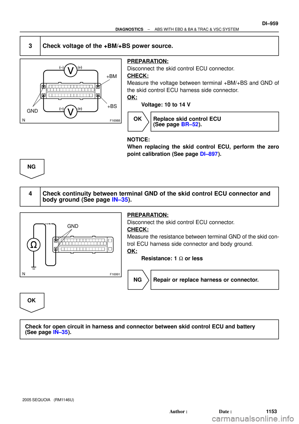
3 Check voltage of the +BM/+BS power source.
PREPARATION:
Disconnect the skid control ECU connector.
CHECK:
Measure the voltage between terminal +BM/+BS and GND of
the skid control ECU harness side connector.
OK:
Voltage: 10 to 14 V
OK Replace skid control ECU
(See page BR±52).
NOTICE:
When replacing the skid control ECU, perform the zero
point calibration (See page DI±897).
NG
4 Check continuity between terminal GND of the skid control ECU connector and
body ground (See page IN±35).
PREPARATION:
Disconnect the skid control ECU connector.
CHECK:
Measure the resistance between terminal GND of the skid con-
trol ECU harness side connector and body ground.
OK:
Resistance: 1 W or less
NG Repair or replace harness or connector.
OK
Check for open circuit in harness and connector between skid control ECU and battery
(See page IN±35).

IFL
IFR
IRL
IRR
OFL
OFR
ORL
ORR
ASR1
SV1
SV2")

IG J18
J/C
A A3
ABS
Motor Relay
Pump
Motor IL117
IL19")

CANH
CANL
IG1
8
3C8
3A
B±R Instrum")

ALT
B
58W1
1L
1AM1
6
1C
2
4
1F4
1C Sub J/B No.3
8
3C8
3AW±L
12
ECU±IGAM1IG1
B±Y B±R
B±R
B±")

IG J18
J/C
A A3
ABS
Motor Relay
Pump
Motor IL117
IL19")