Page 525 of 4323

B17444
Wire Harness Side:
Air Injection Driver Connector
A41
VV
B17440
A46
Air Switching Valve Connector Wire Harness Side:
B17444
Wire Harness Side:
Air Injection Driver Connector
A41
SIV
± DIAGNOSTICSENGINE
DI±323
517 Author�: Date�:
2005 SEQUOIA (RM1146U)
4 Check for open and short in harness and connector between air injection driver
and air switching valve.
PREPARATION:
(a) Remove the intake manifold (see page EM±36).
(b) Disconnect the A41 air injection driver connector.
(c) Disconnect the A46 air switching valve connector.
(d) Disconnect the battery positive terminal cable.
CHECK:
Measure the resistance between the wire harness side connec-
tors.
OK:
Standard:
Tester ConnectionSpecified Condition
VV (A41±6) ± A46±1Below 1 W
VV (A41±6) or A46±1 ±
Battery positive terminal cable10 kW or higher
NG Repair or replace harness or connector.
OK
5 Check voltage between SIV terminal of air injection driver and body ground.
PREPARATION:
(a) Disconnect the A41 air injection driver connector.
(b) Turn the ignition switch ON.
CHECK:
Measure the voltage between terminal 3 (SIV) of the air injec-
tion driver connector and body ground.
OK:
Standard:
Tester ConnectionSpecified Condition
3 (SIV) ± Body ground10 V or more
NG Go to step 6.
OK
Replace air injection driver.
Page 530 of 4323
B17516
Air
Port A
B17517
Air
Port A
DI±328
± DIAGNOSTICSENGINE
522 Author�: Date�:
2005 SEQUOIA (RM1146U)
10 Check VSV for air injection control.
PREPARATION:
Disconnect the connector from the VSV for air injection control.
CHECK:
Check that air does not flow from the port as shown in the il-
lustration.
OK:
Does not flow from port A
CHECK:
Apply battery positive across the terminals, check that air flows
from the ports.
OK:
Flows from port A
NG Replace VSV for air injection control.
OK
Page 533 of 4323

± DIAGNOSTICSENGINE
DI±331
525 Author�: Date�:
2005 SEQUOIA (RM1146U)
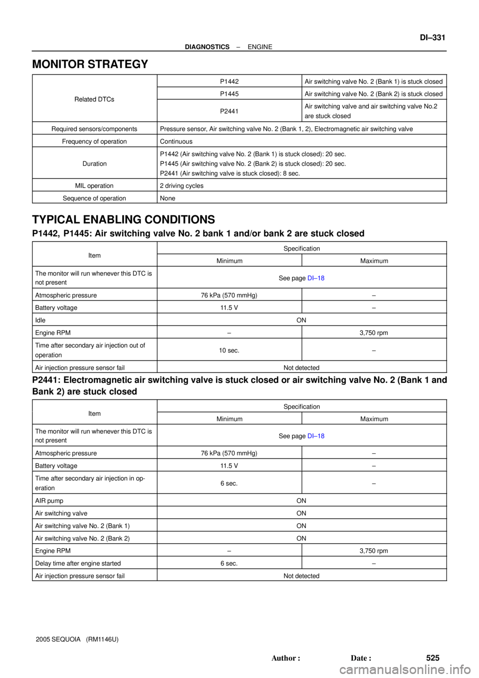
MONITOR STRATEGY
P1442Air switching valve No. 2 (Bank 1) is stuck closed
Related DTCsP1445Air switching valve No. 2 (Bank 2) is stuck closedRelated DTCs
P2441Air switching valve and air switching valve No.2
are stuck closed
Required sensors/componentsPressure sensor, Air switching valve No. 2 (Bank 1, 2), Electromagnetic air switching valve
Frequency of operationContinuous
Duration
P1442 (Air switching valve No. 2 (Bank 1) is stuck closed): 20 sec.
P1445 (Air switching valve No. 2 (Bank 2) is stuck closed): 20 sec.
P2441 (Air switching valve is stuck closed): 8 sec.
MIL operation2 driving cycles
Sequence of operationNone
TYPICAL ENABLING CONDITIONS
P1442, P1445: Air switching valve No. 2 bank 1 and/or bank 2 are stuck closed
ItSpecificationItemMinimumMaximum
The monitor will run whenever this DTC is
not presentSee page DI±18
Atmospheric pressure76 kPa (570 mmHg)±
Battery voltage11.5 V±
IdleON
Engine RPM±3,750 rpm
Time after secondary air injection out of
operation10 sec.±
Air injection pressure sensor failNot detected
P2441: Electromagnetic air switching valve is stuck closed or air switching valve No. 2 (Bank 1 and
Bank 2) are stuck closed
ItSpecificationItemMinimumMaximum
The monitor will run whenever this DTC is
not presentSee page DI±18
Atmospheric pressure76 kPa (570 mmHg)±
Battery voltage11.5 V±
Time after secondary air injection in op-
eration6 sec.±
AIR pumpON
Air switching valveON
Air switching valve No. 2 (Bank 1)ON
Air switching valve No. 2 (Bank 2)ON
Engine RPM±3,750 rpm
Delay time after engine started6 sec.±
Air injection pressure sensor failNot detected
Page 537 of 4323

B17436
A23671
Port APort B
Air
A23672
Port APort B
Battery Air
± DIAGNOSTICSENGINE
DI±335
529 Author�: Date�:
2005 SEQUOIA (RM1146U)
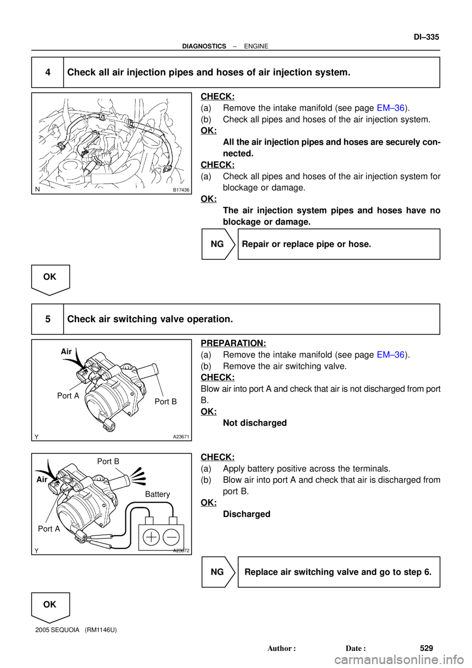
4 Check all air injection pipes and hoses of air injection system.
CHECK:
(a) Remove the intake manifold (see page EM±36).
(b) Check all pipes and hoses of the air injection system.
OK:
All the air injection pipes and hoses are securely con-
nected.
CHECK:
(a) Check all pipes and hoses of the air injection system for
blockage or damage.
OK:
The air injection system pipes and hoses have no
blockage or damage.
NG Repair or replace pipe or hose.
OK
5 Check air switching valve operation.
PREPARATION:
(a) Remove the intake manifold (see page EM±36).
(b) Remove the air switching valve.
CHECK:
Blow air into port A and check that air is not discharged from port
B.
OK:
Not discharged
CHECK:
(a) Apply battery positive across the terminals.
(b) Blow air into port A and check that air is discharged from
port B.
OK:
Discharged
NG Replace air switching valve and go to step 6.
OK
Page 541 of 4323
A23451
B17516
AirA
B17517
AirA
± DIAGNOSTICSENGINE
DI±339
533 Author�: Date�:
2005 SEQUOIA (RM1146U)
10 Check air injection pipe between air switching valve No.2 and exhaust manifold.
CHECK:
(a) Check that the air injection pipe between the air switching
valve(s) No.2 and exhaust manifold is securely con-
nected.
OK:
The air injection pipe is securely connected.
CHECK:
(a) Check the air injection pipe for blockages and damage.
OK:
The air injection pipe have no blockages and damage.
NG Repair or replace air injection pipe.
OK
Check for intermittent problems
(See page DI±11).
11 Check VSV for air injection control.
PREPARATION:
Disconnect the 2 vacuum hoses.
CHECK:
Check that air does not flow from the port A as shown in the il-
lustration.
OK:
Not flow from port A
CHECK:
Apply battery positive across the terminals, check that air flows
from the port A.
OK:
Flow from port A
NG Replace VSV for air injection control.
OK
Page 545 of 4323

± DIAGNOSTICSENGINE
DI±343
537 Author�: Date�:
2005 SEQUOIA (RM1146U)
DTC P1613 Air Injection System Air Injection Driver
CIRCUIT DESCRIPTION
Refer to DTC P0412 on page DI±234.
DTC No.DTC Detection ConditionTrouble Area
P1613
Either of the following condition (a) or (b) is met:
(a) All of the following conditions are met (1 trip detection logic):
�Either the air pump or air switching valve does not operate.
�Air injection driver outputs a normal signal (80% duty signal)
(b) All of the following conditions are met (1 trip detection logic):
�Air injection driver outputs an abnormal duty signal (duty sig-
nal excluding 0, 20, 40, 60, 80, 100%)
�Air injection driver (AID)
�Open in air injection driver ground circuit
P1613
All of the following conditions are met (1 trip detection logic):
(a) Air injection system operates (Air pump ON and all ASV
ON)
(b) Air injection driver outputs an air pump malfunction signal
(0% duty signal)�Short in diagnostic information signal circuit (AID ± ECM)
�Open or short in air pump and air switching valve command
signal circuit (AID ± ECM)
�Air injection driver (AID)
�Open in air injection driver ground circuit
�ECM
P1613Air injection driver outputs an abnormal duty signal (100% duty
signal) (1 trip detection logic)
�Open or short in AID power source circuit
�Open in diagnostic information signal circuit (AID ± ECM)
�Air injection driver (AID)
�ECM
MONITOR DESCRIPTION
When the air injection system operation is required while the engine is warming up, the ECM transmits com-
mand signals to the Air Injection Driver (AID) to drive the air pump and air switching valve.
AID detects an open or short in the air pump and air switching valve circuit according to the terminal voltage
and sends a signal as diagnostic information to the ECM.
If the air injection system drive circuit or the AID itself has a malfunction, the AID sends a malfunction signal
(duty signal) as a diagnostic information signal to the ECM (when the system is normal, a system normal
signal is sent).
The ECM sets the DTC based on the diagnostic information from the AID.
Example:
(1) The duty ratio of the diagnostic information signal output from the AID is 0 or 100% (remains at
0 V or battery voltage).
(2) The duty ratio output from the AID is the ratio to output the impossible (excluding 0, 20, 40, 60,
80, 100%).
(3) The AID outputs the normal signal (normal duty signal: 80%) while the system is not operating.
DIDMX±01
Page 546 of 4323

DI±344
± DIAGNOSTICSENGINE
538 Author�: Date�:
2005 SEQUOIA (RM1146U)
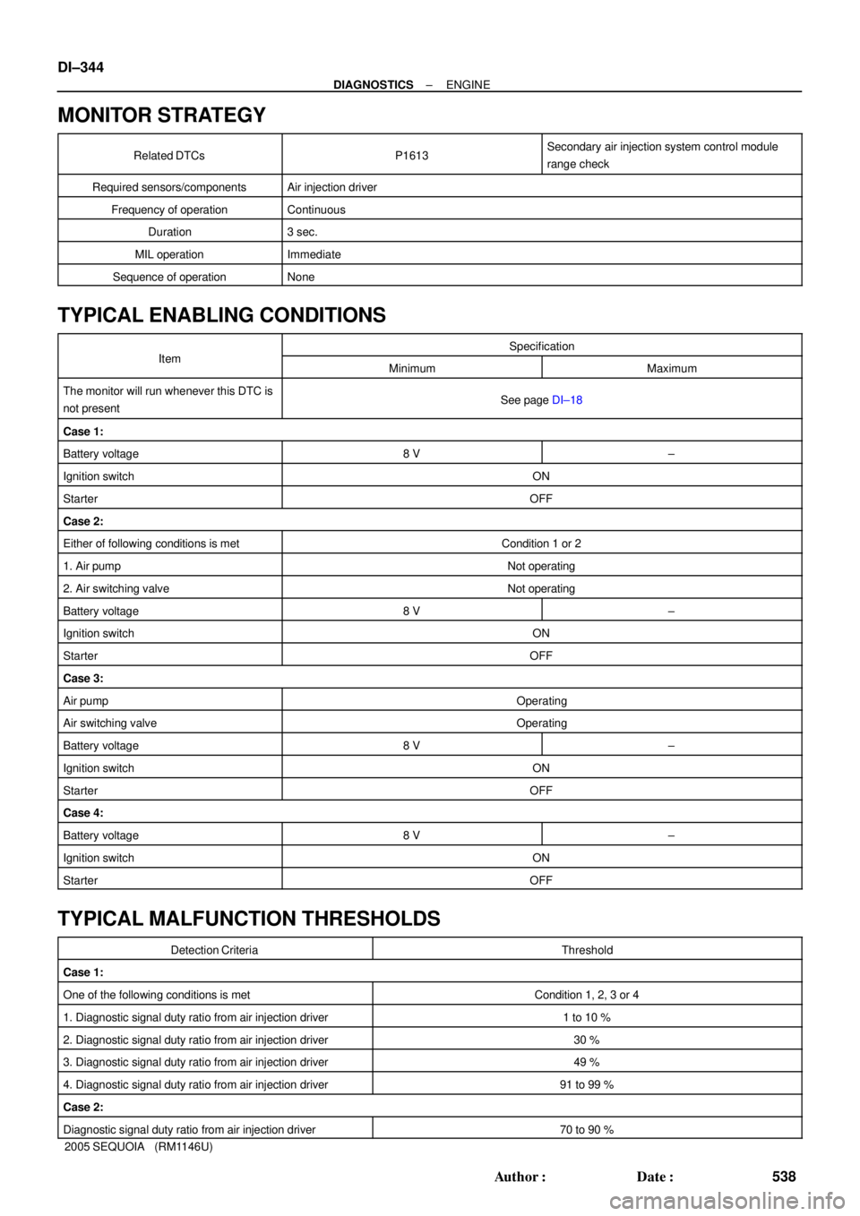
MONITOR STRATEGY
Related DTCsP1613Secondary air injection system control module
range check
Required sensors/componentsAir injection driver
Frequency of operationContinuous
Duration3 sec.
MIL operationImmediate
Sequence of operationNone
TYPICAL ENABLING CONDITIONS
ItSpecificationItemMinimumMaximum
The monitor will run whenever this DTC is
not presentSee page DI±18
Case 1:
Battery voltage8 V±
Ignition switchON
StarterOFF
Case 2:
Either of following conditions is metCondition 1 or 2
1. Air pumpNot operating
2. Air switching valveNot operating
Battery voltage8 V±
Ignition switchON
StarterOFF
Case 3:
Air pumpOperating
Air switching valveOperating
Battery voltage8 V±
Ignition switchON
StarterOFF
Case 4:
Battery voltage8 V±
Ignition switchON
StarterOFF
TYPICAL MALFUNCTION THRESHOLDS
Detection CriteriaThreshold
Case 1:
One of the following conditions is metCondition 1, 2, 3 or 4
1. Diagnostic signal duty ratio from air injection driver1 to 10 %
2. Diagnostic signal duty ratio from air injection driver30 %
3. Diagnostic signal duty ratio from air injection driver49 %
4. Diagnostic signal duty ratio from air injection driver91 to 99 %
Case 2:
Diagnostic signal duty ratio from air injection driver70 to 90 %
Page 549 of 4323

A23464
AID Diagnostic Signal WaveformsECM
CommandsDTCs
Suspected Trouble Areas
(ECM Output)
100 % Duty ratio
+B
Almost Battery Voltage
GND
0 % Duty ratio
+B
Fixed at Low Voltage
GND
20 % Duty ratio
20 %
+B
GND
40 % Duty ratio
40 %
+B
GND
80 % Duty ratio
80 %
+B
GND
Excluding above
(excluding 0, 20, 40, 80, 100 % duty)
Air Pump: ON
Air Pump: OFF
ASV: ON
ASV: OFF
AI System: OFF
(Air pump OFF,
ASV OFF)
AI System: ON
(Air pump ON,
ASV ON)
P1613
P0418
P0418
P0412
P0412
P1613
P1613
Air Injection Control Driver (AID)
Open in AID+B circuit (AID power source)
Open or short in air pump or Air Switching Valve
AID
ECM
Open in air pump drive circuit (AID±Pump) ,Harness & connector (AID±Pump)
Air PumpAIDECM
Short between air pump drive circuit and body ground
AID
ECM
Harness & connector (AID±Pump)Air Pump
Open in ASV drive circuit (AID±ASV),Harness & connector (AID±ASV)
ASVAIDECM
Short between ASV drive circuit and body ground
Harness & connector (AID±ASV)
AID
ECM
ECM
Normal
AID
AID
or short between air pump drive circuit and +B
or short between ASV drive circuit and +B
'
'
ASV
±
AI System: OFF
(Air pump OFF,
ASV OFF) AI System: ON
(Air pump ON,
ASV ON)
Normal Any Air Injection
(AI) System op-
eration
P1613
Open in AID ground circuit
Short between +B circuit and diagnostic signal circuit
Short between diagnostic signal circuit and body
(ASV) command signal circuit (ECM±AID)
ground
Open in AID ground circuit
Open in diagnostic signal circuit
± DIAGNOSTICSENGINE
DI±347
541 Author�: Date�:
2005 SEQUOIA (RM1146U)