Page 432 of 4323

A23464
AID Diagnostic Signal WaveformsECM
CommandsDTCs
Suspected Trouble Areas
(ECM Output)
100 % Duty ratio
+B
Almost Battery Voltage
GND
0 % Duty ratio
+B
Fixed at Low Voltage
GND
20 % Duty ratio
20 %
+B
GND
40 % Duty ratio
40 %
+B
GND
80 % Duty ratio
80 %
+B
GND
Excluding above
(excluding 0, 20, 40, 80, 100 % duty)
Air Pump: ON
Air Pump: OFF
ASV: ON
ASV: OFF
AI System: OFF
(Air pump OFF,
ASV OFF)
AI System: ON
(Air pump ON,
ASV ON)
P1613
P0418
P0418
P0412
P0412
P1613
P1613
Air Injection Control Driver (AID)
Open in AID+B circuit (AID power source)
Open or short in air pump or Air Switching Valve
AID
ECM
Open in air pump drive circuit (AID±Pump) ,Harness & connector (AID±Pump)
Air PumpAIDECM
Short between air pump drive circuit and body ground
AID
ECM
Harness & connector (AID±Pump)Air Pump
Open in ASV drive circuit (AID±ASV),Harness & connector (AID±ASV)
ASVAIDECM
Short between ASV drive circuit and body ground
Harness & connector (AID±ASV)
AID
ECM
ECM
Normal
AID
AID
or short between air pump drive circuit and +B
or short between ASV drive circuit and +B
'
'
ASV
±
AI System: OFF
(Air pump OFF,
ASV OFF) AI System: ON
(Air pump ON,
ASV ON)
Normal Any Air Injection
(AI) System op-
eration
P1613
Open in AID ground circuit
Short between +B circuit and diagnostic signal circuit
Short between diagnostic signal circuit and body
(ASV) command signal circuit (ECM±AID)
ground
Open in AID ground circuit
Open in diagnostic signal circuit
DI±238
± DIAGNOSTICSENGINE
432 Author�: Date�:
2005 SEQUOIA (RM1146U)
Page 437 of 4323
± DIAGNOSTICSENGINE
DI±243
437 Author�: Date�:
2005 SEQUOIA (RM1146U)
TYPICAL ENABLING CONDITIONS
ItSpecificationItemMinimumMaximum
The monitor will run whenever this DTC is
not presentSee page DI±18
Case 1:
Air pumpOperating
Air switching valveOperating
Battery voltage8 V±
Ignition switchON
StarterOFF
Case 2:
Air pumpNot operating
Air switching valveNot operating
Battery voltage8 V±
Ignition switchON
StarterOFF
TYPICAL MALFUNCTION THRESHOLDS
Detection CriteriaThreshold
Case 1, 2:
Diagnostic signal duty ratio from air injection driver11 to 29 %
COMPONENT OPERATING RANGE
ParameterStandard Value
Diagnostic signal duty ratio from air injection driver
70 to 90% when secondary air injection system operating
and
0% when secondary air injection system not operating
WIRING DIAGRAM
Refer to DTC P0412 on page DI±234.
Page 439 of 4323

A23464
AID Diagnostic Signal WaveformsECM
CommandsDTCs
Suspected Trouble Areas
(ECM Output)
100 % Duty ratio
+B
Almost Battery Voltage
GND
0 % Duty ratio
+B
Fixed at Low Voltage
GND
20 % Duty ratio
20 %
+B
GND
40 % Duty ratio
40 %
+B
GND
80 % Duty ratio
80 %
+B
GND
Excluding above
(excluding 0, 20, 40, 80, 100 % duty)
Air Pump: ON
Air Pump: OFF
ASV: ON
ASV: OFF
AI System: OFF
(Air pump OFF,
ASV OFF)
AI System: ON
(Air pump ON,
ASV ON)
P1613
P0418
P0418
P0412
P0412
P1613
P1613
Air Injection Control Driver (AID)
Open in AID+B circuit (AID power source)
Open or short in air pump or Air Switching Valve
AID
ECM
Open in air pump drive circuit (AID±Pump) ,Harness & connector (AID±Pump)
Air PumpAIDECM
Short between air pump drive circuit and body ground
AID
ECM
Harness & connector (AID±Pump)Air Pump
Open in ASV drive circuit (AID±ASV),Harness & connector (AID±ASV)
ASVAIDECM
Short between ASV drive circuit and body ground
Harness & connector (AID±ASV)
AID
ECM
ECM
Normal
AID
AID
or short between air pump drive circuit and +B
or short between ASV drive circuit and +B
'
'
ASV
±
AI System: OFF
(Air pump OFF,
ASV OFF) AI System: ON
(Air pump ON,
ASV ON)
Normal Any Air Injection
(AI) System op-
eration
P1613
Open in AID ground circuit
Short between +B circuit and diagnostic signal circuit
Short between diagnostic signal circuit and body
(ASV) command signal circuit (ECM±AID)
ground
Open in AID ground circuit
Open in diagnostic signal circuit
± DIAGNOSTICSENGINE
DI±245
439 Author�: Date�:
2005 SEQUOIA (RM1146U)
Page 444 of 4323

DI±250
± DIAGNOSTICSENGINE
444 Author�: Date�:
2005 SEQUOIA (RM1146U)
MONITOR STRATEGY
RltdDTCP0420Bank 1 catalyst is deterioratedRelated DTCsP0430Bank 2 catalyst is deteriorated
Main sensors/componentsFront and rear heated oxygen sensor
Required sensors/componentsRelated sensors/components
Mass air flow meter, Engine coolant temperature
sensor, Engine speed sensor, Intake air tempera-
ture sensor
Frequency of operationOnce per driving cycle
Duration20 sec.
MIL operation2 driving cycles
Sequence of operationNone
TYPICAL ENABLING CONDITIONS
ItSpecificationItemMinimumMaximum
The monitor will run whenever these
DTCs are not presentSee page DI±18
Battery voltage11 V±
Intake air temperature±10�C (14�F)±
Engine coolant temperature75°C (167°F)±
Atmospheric pressure coefficient0.75±
IdleOFF
Engine RPM±3,200 rpm
A/F sensorActivated
Fuel system statusClosed loop
Engine load10 to 70 %
All of the following conditions are metCondition 1, 2 and 3
1. MAF6�to 75 g/sec
2. Front catalyst temperature (estimated)620�to 830�C (1,148 to 1,526�F)
3. Rear catalyst temperature (estimated)410 to 830�C (770 to 1,526�F)
Rear HO2S monitorCompleted
Shift position4th±
TYPICAL MALFUNCTION THRESHOLDS
Detection CriteriaThreshold
Oxygen storage capacity (OSC) of catalystLess than 0.16
Page 452 of 4323

DI±250
± DIAGNOSTICSENGINE
444 Author�: Date�:
2005 SEQUOIA (RM1146U)
MONITOR STRATEGY
RltdDTCP0420Bank 1 catalyst is deterioratedRelated DTCsP0430Bank 2 catalyst is deteriorated
Main sensors/componentsFront and rear heated oxygen sensor
Required sensors/componentsRelated sensors/components
Mass air flow meter, Engine coolant temperature
sensor, Engine speed sensor, Intake air tempera-
ture sensor
Frequency of operationOnce per driving cycle
Duration20 sec.
MIL operation2 driving cycles
Sequence of operationNone
TYPICAL ENABLING CONDITIONS
ItSpecificationItemMinimumMaximum
The monitor will run whenever these
DTCs are not presentSee page DI±18
Battery voltage11 V±
Intake air temperature±10�C (14�F)±
Engine coolant temperature75°C (167°F)±
Atmospheric pressure coefficient0.75±
IdleOFF
Engine RPM±3,200 rpm
A/F sensorActivated
Fuel system statusClosed loop
Engine load10 to 70 %
All of the following conditions are metCondition 1, 2 and 3
1. MAF6�to 75 g/sec
2. Front catalyst temperature (estimated)620�to 830�C (1,148 to 1,526�F)
3. Rear catalyst temperature (estimated)410 to 830�C (770 to 1,526�F)
Rear HO2S monitorCompleted
Shift position4th±
TYPICAL MALFUNCTION THRESHOLDS
Detection CriteriaThreshold
Oxygen storage capacity (OSC) of catalystLess than 0.16
Page 463 of 4323

± DIAGNOSTICSENGINE
DI±261
455 Author�: Date�:
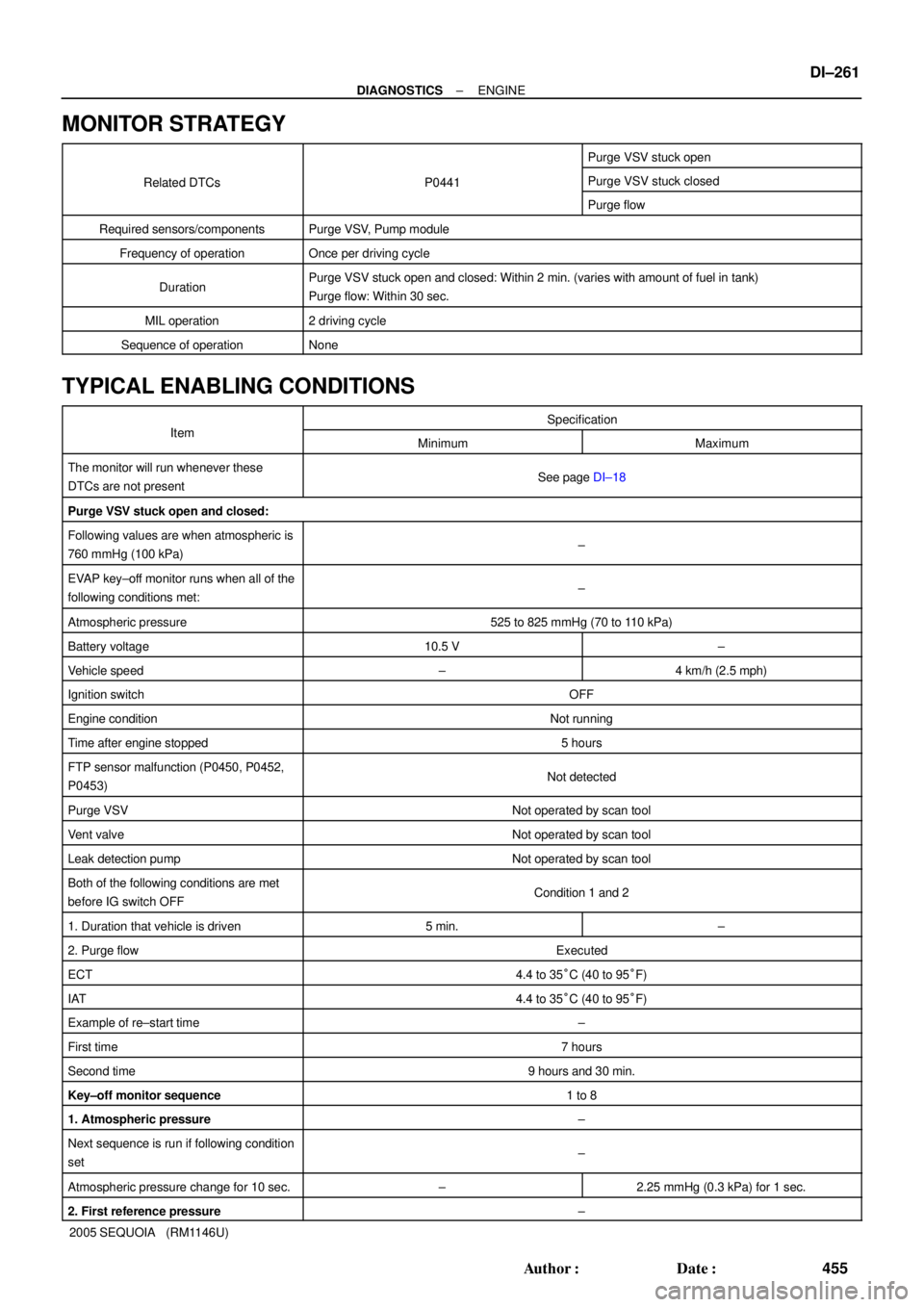
2005 SEQUOIA (RM1146U)
MONITOR STRATEGY
Purge VSV stuck open
Related DTCsP0441Purge VSV stuck closedRelated DTCsP0441
Purge flow
Required sensors/componentsPurge VSV, Pump module
Frequency of operationOnce per driving cycle
DurationPurge VSV stuck open and closed: Within 2 min. (varies with amount of fuel in tank)
Purge flow: Within 30 sec.
MIL operation2 driving cycle
Sequence of operationNone
TYPICAL ENABLING CONDITIONS
ItSpecificationItemMinimumMaximum
The monitor will run whenever these
DTCs are not presentSee page DI±18
Purge VSV stuck open and closed:
Following values are when atmospheric is
760 mmHg (100 kPa)±
EVAP key±off monitor runs when all of the
following conditions met:±
Atmospheric pressure525 to 825 mmHg (70 to 110 kPa)
Battery voltage10.5 V±
Vehicle speed±4 km/h (2.5 mph)
Ignition switchOFF
Engine conditionNot running
Time after engine stopped5 hours
FTP sensor malfunction (P0450, P0452,
P0453)Not detected
Purge VSVNot operated by scan tool
Vent valveNot operated by scan tool
Leak detection pumpNot operated by scan tool
Both of the following conditions are met
before IG switch OFFCondition 1 and 2
1. Duration that vehicle is driven5 min.±
2. Purge flowExecuted
ECT4.4 to 35°C (40 to 95°F)
IAT4.4 to 35°C (40 to 95°F)
Example of re±start time±
First time7 hours
Second time9 hours and 30 min.
Key±off monitor sequence1 to 8
1. Atmospheric pressure±
Next sequence is run if following condition
set±
Atmospheric pressure change for 10 sec.±2.25 mmHg (0.3 kPa) for 1 sec.
2. First reference pressure±
Page 465 of 4323
± DIAGNOSTICSENGINE
DI±263
457 Author�: Date�:
2005 SEQUOIA (RM1146U) Battery voltage
10 V±
Purge duty cycle8 %±
TYPICAL MALFUNCTION THRESHOLDS
Detection CriteriaThreshold
Purge VSV stuck open:
FTP when vacuum introduction was compleatHigher than reference pressure x 0.2
Purge VSV stuck closed:
FTP change for 10 sec. after purge VSV ONLess than 2.25 mmHg (0.3 kPa)
Purge flow:
Both of the following conditions are metCondition 1 or 2
1. FTP change when purge operation is startedLess than 0.75 mmHg (0.1 kPa)
2. FTP change during purge operation when vent valve is
closedLess than 3.75 mmHg (0.5 kPa)
MONITOR RESULT (MODE 06 DATA)
Refer to page DI±26 for detailed information on Monitor Result.
INSPECTION PROCEDURE
Refer to the EVAP Inspection Procedure (see page DI±460).
Page 468 of 4323

DI±266
± DIAGNOSTICSENGINE
460 Author�: Date�:
2005 SEQUOIA (RM1146U)
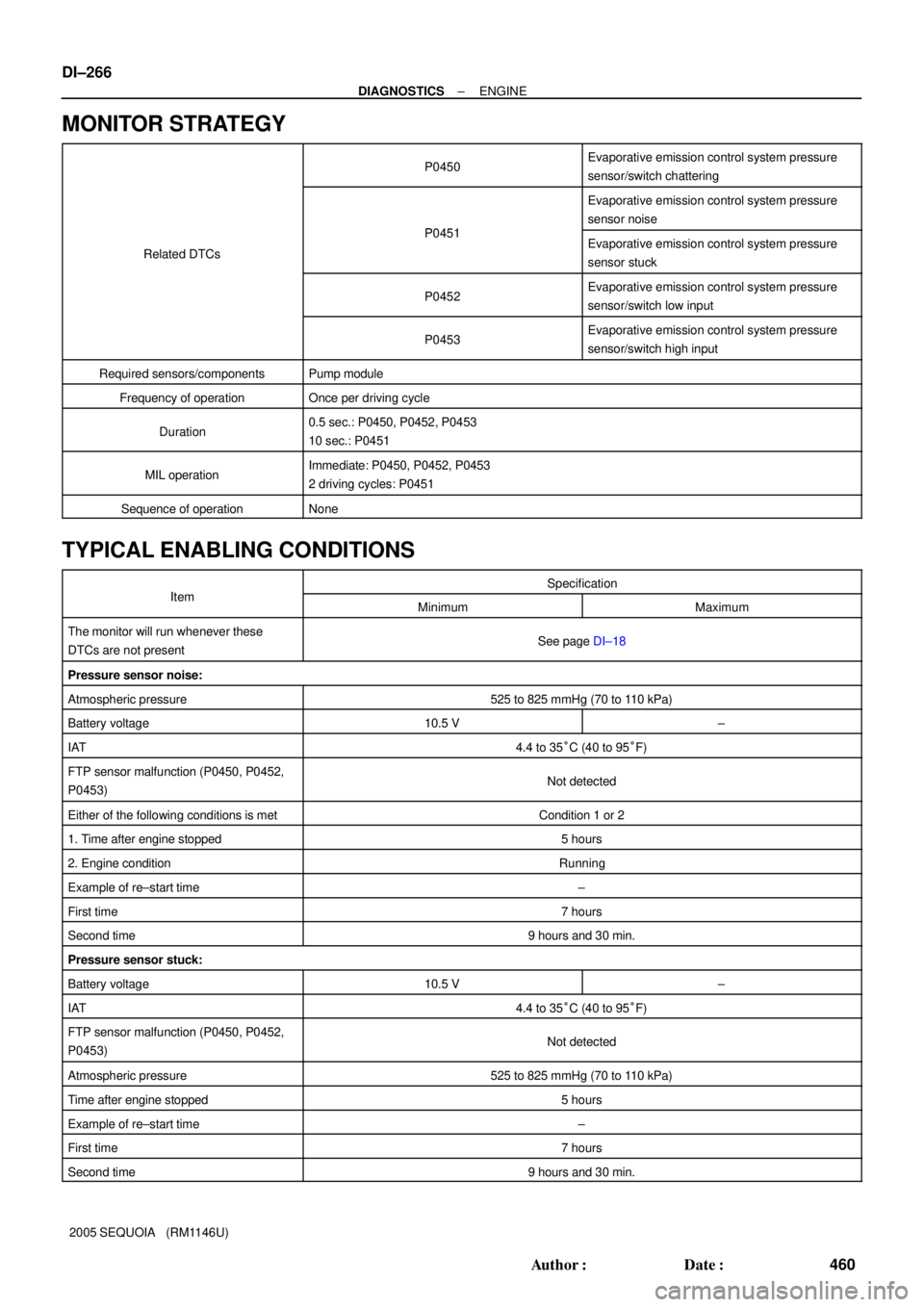
MONITOR STRATEGY
P0450Evaporative emission control system pressure
sensor/switch chattering
P0451
Evaporative emission control system pressure
sensor noise
Related DTCs
P0451Evaporative emission control system pressure
sensor stuck
P0452Evaporative emission control system pressure
sensor/switch low input
P0453Evaporative emission control system pressure
sensor/switch high input
Required sensors/componentsPump module
Frequency of operationOnce per driving cycle
Duration0.5 sec.: P0450, P0452, P0453
10 sec.: P0451
MIL operationImmediate: P0450, P0452, P0453
2 driving cycles: P0451
Sequence of operationNone
TYPICAL ENABLING CONDITIONS
ItSpecificationItemMinimumMaximum
The monitor will run whenever these
DTCs are not presentSee page DI±18
Pressure sensor noise:
Atmospheric pressure525 to 825 mmHg (70 to 110 kPa)
Battery voltage10.5 V±
IAT4.4 to 35°C (40 to 95°F)
FTP sensor malfunction (P0450, P0452,
P0453)Not detected
Either of the following conditions is metCondition 1 or 2
1. Time after engine stopped5 hours
2. Engine conditionRunning
Example of re±start time±
First time7 hours
Second time9 hours and 30 min.
Pressure sensor stuck:
Battery voltage10.5 V±
IAT4.4 to 35°C (40 to 95°F)
FTP sensor malfunction (P0450, P0452,
P0453)Not detected
Atmospheric pressure525 to 825 mmHg (70 to 110 kPa)
Time after engine stopped5 hours
Example of re±start time±
First time7 hours
Second time9 hours and 30 min.