Page 2332 of 4323

I28750
Radio and Navigation Assy:
R27
RSLD
R±R+
R±R± R±L+ R±L±
I28614
SG2R23
Multi±display Controller Sub±assy:
R±R+
R±R±R±L+R±L±
DI±2130
± DIAGNOSTICSREAR SEAT ENTERTAINMANT SYSTEM
2324 Author�: Date�:
2005 SEQUOIA (RM1146U)
INSPECTION PROCEDURE
1 Check harness and connector (Radio and navigation assy ± Multi±display con-
troller sub±assy).
PREPARATION:
Disconnect the R23 and R27 connectors.
CHECK:
Measure the resistance according to the value(s) in the table
below.
OK:
Symbol (Tester connection)ConditionSpecified condition
R±R+ (R27±15) ± R±R+ (R23±26)AlwaysBelow 1 W
R±R± (R27±16) ± R±R± (R23±25)AlwaysBelow 1 W
R±L+ (R27±17) ± R±L+ (R23±24)AlwaysBelow 1 W
R±L± (R27±18) ± R±L± (R23±23)AlwaysBelow 1 W
RSLD (R27±14) ± SG2 (R23±27)AlwaysBelow 1 W
R±R+ (R27±15) ± Body groundAlways10 kW or higher
R±R± (R27±16) ± Body groundAlways10 kW or higher
R±L+ (R27±17) ± Body groundAlways10 kW or higher
R±L± (R27±18) ± Body groundAlways10 kW or higher
RSLD (R27±14) ± Body groundAlways10 kW or higher
NG Repair or replace harness or connector.
OK
Proceed to next circuit inspection shown in problem symptoms table (See page DI±2087).
Page 2334 of 4323
I28321I28327
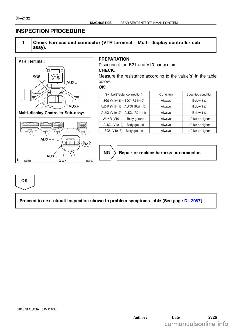
VTR Terminal:
Multi±display Controller Sub±assy:SG6
V10
R21
AUXL
AUXR
AUXR
AUXL
SG7
DI±2132
± DIAGNOSTICSREAR SEAT ENTERTAINMANT SYSTEM
2326 Author�: Date�:
2005 SEQUOIA (RM1146U)
INSPECTION PROCEDURE
1 Check harness and connector (VTR terminal ± Multi±display controller sub±
assy).
PREPARATION:
Disconnect the R21 and V10 connectors.
CHECK:
Measure the resistance according to the value(s) in the table
below.
OK:
Symbol (Tester connection)ConditionSpecified condition
SG6 (V10±3) ± SG7 (R21±10)AlwaysBelow 1 W
AUXR (V10±1) ± AUXR (R21±12)AlwaysBelow 1 W
AUXL (V10±2) ± AUXL (R21±11)AlwaysBelow 1 W
AUXR (V10±1) ± Body groundAlways10 kW or higher
AUXL (V10±2) ± Body groundAlways10 kW or higher
SG6 (V10±3) ± Body groundAlways10 kW or higher
NG Repair or replace harness or connector.
OK
Proceed to next circuit inspection shown in problem symptoms table (See page DI±2087).
Page 2336 of 4323

I28333
Headphone Terminal:
Multi±display Controller Sub±assy:
SG5HP1L
HP1R
SG6
HP2L HP2R R21
H10
H11
HPR
HPL
SGND
DI±2134
± DIAGNOSTICSREAR SEAT ENTERTAINMANT SYSTEM
2328 Author�: Date�:
2005 SEQUOIA (RM1146U)
INSPECTION PROCEDURE
1 Check harness and connector (Headphone terminal ± Multi±display controller
sub±assy).
PREPARATION:
Disconnect the H10 (H11) and R21 connectors.
CHECK:
Measure the resistance according to the value(s) in the table
below.
OK:
Symbol (Tester connection)ConditionSpecified condition
HPR (H10±1) ± HP1R (R21±9)AlwaysBelow 1 W
HPL (H10±2) ± HP1L (R21±8)AlwaysBelow 1 W
HPR (H11±1) ± HP2R (R21±21)AlwaysBelow 1 W
HPL (H11±2) ± HP2L (R21±20)AlwaysBelow 1 W
SGND (H10±3) ± SG5 (R21±7)AlwaysBelow 1 W
SGND (H11±3) ± SG6 (R21±19)AlwaysBelow 1 W
HPR (H10±1, H11±1) ± Body groundAlways10 kW or higher
HPL (H10±2, H11±2) ± Body groundAlways10 kW or higher
SGND (H10±3, H11±3) ± Body groundAlways10 kW or higher
SGND (H10±3) ± Body groundAlways10 kW or higher
SGND (H11±3) ± Body groundAlways10 kW or higher
NG Repair or replace harness or connector.
OK
Proceed to next circuit inspection shown in problem symptoms table (See page DI±2087).
Page 2338 of 4323

I28332
Television Display Assy: Multi±display Controller Sub±assy:
HPL± HPL+
HPR+
HPR± SLD1
SGND
R+
R±
L+ L±
R22
R25
DI±2136
± DIAGNOSTICSREAR SEAT ENTERTAINMANT SYSTEM
2330 Author�: Date�:
2005 SEQUOIA (RM1146U)
INSPECTION PROCEDURE
1 Check harness and connector (Multi±display controller sub±assy ± Television
display assy).
PREPARATION:
Disconnect the R22 and R25 connectors.
CHECK:
Measure the resistance according to the value(s) in the table
below.
OK:
Symbol (Tester connection)ConditionSpecified condition
HPR+ (R22±19) ± R+ (R25±3)AlwaysBelow 1 W
HPR± (R22±18) ± R± (R25±4)AlwaysBelow 1 W
HPL+ (R22±17) ± L+ (R25±5)AlwaysBelow 1 W
HPL± (R22±16) ± L± (R25±6)AlwaysBelow 1 W
SLD1 (R22±20) ± SGND (R25±2)AlwaysBelow 1 W
HPR+ (R22±19) ± Body groundAlways10 kW or higher
HPR± (R22±18) ± Body groundAlways10 kW or higher
HPL+ (R22±17) ± Body groundAlways10 kW or higher
HPL± (R22±16) ± Body groundAlways10 kW or higher
SLD1 (R22±20) ± Body groundAlways10 kW or higher
NG Repair or replace harness or connector.
OK
Proceed to next circuit inspection shown in problem symptoms table (See page DI±2087).
Page 2340 of 4323

I28330
Disc Player Controller:
Multi±display Controller Sub±assy:
R+L+R± L±
SLD
AL+AR+
AR±SG4AL± D23
R22
DI±2138
± DIAGNOSTICSREAR SEAT ENTERTAINMANT SYSTEM
2332 Author�: Date�:
2005 SEQUOIA (RM1146U)
INSPECTION PROCEDURE
1 Check harness and connector (Multi±display controller sub±assy ± Disc player
controller).
PREPARATION:
Disconnect the R22 and D23 connectors.
CHECK:
Measure the resistance according to the value(s) in the table
below.
OK:
Symbol (Tester connection)ConditionSpecified condition
L± (D23±9) ± AL± (R22±2)AlwaysBelow 1 W
L+ (D23±8) ± AL+ (R22±3)AlwaysBelow 1 W
R± (D23±7) ± AR± (R22±4)AlwaysBelow 1 W
R+ (D23±6) ± AR+ (R22±5)AlwaysBelow 1 W
SLD (D23±5) ± SG4 (R22±6)AlwaysBelow 1 W
L± (D23±9) ± Body groundAlways10 kW or higher
L+ (D23±8) ± Body groundAlways10 kW or higher
R± (D23±7) ± Body groundAlways10 kW or higher
R+ (D23±6) ± Body groundAlways10 kW or higher
SLD (D23±5) ± Body groundAlways10 kW or higher
NG Repair or replace harness or connector.
OK
Proceed to next circuit inspection shown in problem symptoms table (See page DI±2087).
Page 2342 of 4323
DI±2140
± DIAGNOSTICSREAR SEAT ENTERTAINMANT SYSTEM
2334 Author�: Date�:
2005 SEQUOIA (RM1146U)
INSPECTION PROCEDURE
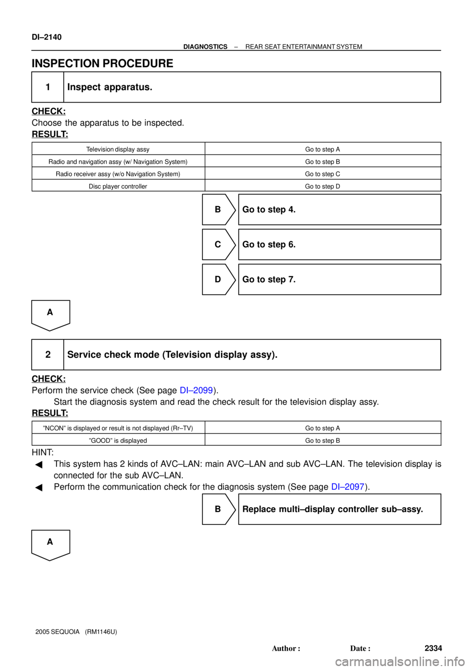
1 Inspect apparatus.
CHECK:
Choose the apparatus to be inspected.
RESULT:
Television display assyGo to step A
Radio and navigation assy (w/ Navigation System)Go to step B
Radio receiver assy (w/o Navigation System)Go to step C
Disc player controllerGo to step D
B Go to step 4.
C Go to step 6.
D Go to step 7.
A
2 Service check mode (Television display assy).
CHECK:
Perform the service check (See page DI±2099).
Start the diagnosis system and read the check result for the television display assy.
RESULT:
ºNCONº is displayed or result is not displayed (Rr±TV)Go to step A
ºGOODº is displayedGo to step B
HINT:
�This system has 2 kinds of AVC±LAN: main AVC±LAN and sub AVC±LAN. The television display is
connected for the sub AVC±LAN.
�Perform the communication check for the diagnosis system (See page DI±2097).
B Replace multi±display controller sub±assy.
A
Page 2344 of 4323
DI±2142
± DIAGNOSTICSREAR SEAT ENTERTAINMANT SYSTEM
2336 Author�: Date�:
2005 SEQUOIA (RM1146U)
4 Service check mode (Multi±display controller sub±assy).
CHECK:
Perform the service check (See page DI±2099).
Start the diagnosis system and read the check result for the radio and navigation assy.
RESULT:
ºNCONº is displayed or result is not displayed (RSE ECU)Go to step A
ºGOODº is displayedGo to step B
HINT:
�This system has 2 kinds of AVC±LAN: main AVC±LAN and sub AVC±LAN. The television display is
connected for the sub AVC±LAN.
�Perform the communication check for the diagnosis system (See page DI±2097).
B Replace radio and navigation assy.
A
Page 2345 of 4323

I28750
Radio and Navigation Assy:
TX±TX+
R27
I28614
TX+ Multi±display Controller Sub±assy:
R23TX±
± DIAGNOSTICSREAR SEAT ENTERTAINMANT SYSTEM
DI±2143
2337 Author�: Date�:
2005 SEQUOIA (RM1146U)
5 Check harness and connector (Radio and navigation assy ± multi±display con-
troller sub±assy).
PREPARATION:
Disconnect the R23 and R27 connectors.
CHECK:
Measure the resistance according to the value(s) in the table
below.
OK:
Symbol (Tester connection)ConditionSpecified condition
TX+ (R27±9) ± TX+ (R23±31)AlwaysBelow 1 W
TX± (R27±10) ± TX± (R23±30)AlwaysBelow 1 W
TX+ (R27±9) ± Body groundAlways10 kW or higher
TX± (R27±10) ± Body groundAlways10 kW or higher
NG Repair or replace harness or connector.
OK
Replace multi±display controller sub±assy.
6 Service check mode (Multi±display controller sub±assy).
CHECK:
Perform the service check (See page DI±2099).
Start the diagnosis system and read the check result for the radio and navigation assy.
RESULT:
ºNCONº is displayed or result is not displayed (RSE ECU)Go to step A
ºGOODº is displayedGo to step B
HINT:
�This system has 2 kinds of AVC±LAN: main AVC±LAN and sub AVC±LAN. The television display is
connected for the sub AVC±LAN.
�Perform the communication check for the diagnosis system (See page DI±2097).
B Replace radio receiver assy.
A