Page 2347 of 4323

8 Ser")
I28617
Disc Player Controller:
Multi±display Controller Sub±assy:TX±
TX+
TX3±
TX3+
D23
R22
± DIAGNOSTICSREAR SEAT ENTERTAINMANT SYSTEM
DI±2145
2339 Author�: Date�:
2005 SEQUOIA (RM1146U)
8 Service check mode (Disc player controller).
CHECK:
Perform the service check (See page DI±2099).
Start the diagnosis system and read the check result for the disc player controller.
RESULT:
ºNCONº is displayed or result is not displayed (DVD±P)Go to step A
ºGOODº is displayedGo to step B
HINT:
�This system has 2 kinds of AVC±LAN: main AVC±LAN and sub AVC±LAN. The television display is
connected for the sub AVC±LAN.
�Perform the communication check for the diagnosis system (See page DI±2097).
B Replace multi±display controller sub±assy.
A
9 Check harness and connector (Disc player controller ± Multi±display controller
sub±assy).
PREPARATION:
Disconnect the R22 and D23 connectors.
CHECK:
Measure the resistance according to the value(s) in the table
below.
OK:
Symbol (Tester connection)ConditionSpecified condition
TX+ (D23±17) ± TX3+ (R22±14)AlwaysBelow 1 W
TX± (D23±18) ± TX3± (R22±13)AlwaysBelow 1 W
TX+ (D23±17)± Body groundAlways10 kW or higher
TX± (D23±18) ± Body groundAlways10 kW or higher
NG Repair or replace harness or connector.
OK
Page 2350 of 4323
I28610
RMUT
R23
LMUT
DI±2148
± DIAGNOSTICSREAR SEAT ENTERTAINMANT SYSTEM
2342 Author�: Date�:
2005 SEQUOIA (RM1146U)
INSPECTION PROCEDURE
1 Inspect multi±display controller sub±assy.
PREPARATION:
Make sure that the R23 connector is connected.
CHECK:
Measure the voltage according to the value(s) in the table be-
low.
OK:
Symbol (Tester connection)ConditionSpecification
RMUT (R23±28) ±
Body groundTurn ignition switch to
ACC, Audio system is
sounding "Changing
Above 3.5 V " Below 1 V
LMUT (R23±12) ±
Body groundTurn ignition switch to
ACC, RSE system is
sounding "Changing
Above 3.5 V " Below 1 V
OK Proceed to next circuit inspection shown in
problem symptoms table (See page DI±2087).
NG
2 Check system.
CHECK:
Check whether the vehicle is equipped with a navigation system or not.
RESULT:
w/o Navigation systemGo to step A
w/ Navigation systemGo to step B
B Go to step 5.
A
Page 2355 of 4323

I28378
Multi±display
Controller Sub±assy
LG1
MUTE R22
MUTE D23
Disc Player Controller
10
I28610
R22
MUTE Multi±display Controller Sub±assy:
± DIAGNOSTICSREAR SEAT ENTERTAINMANT SYSTEM
DI±2153
2347 Author�: Date�:
2005 SEQUOIA (RM1146U)
Mute signal circuit (Disc player controller ± Multi±display control-
ler sub±assy)
CIRCUIT DESCRIPTION
The multi±display controller sub±assy controls the volume according to the MUTE signal from the disc player
controller.
The MUTE signal is sent to reduce noise and a popping sound generated when the mode, etc. is switched.
WIRING DIAGRAM
INSPECTION PROCEDURE
1 Inspect multi±display controller sub±assy.
PREPARATION:
Make sure that the R22 connector is connected.
CHECK:
Measure the voltage according to the value(s) in the table be-
low.
OK:
Symbol
(Tester connection)ConditionSpecification
MUTE (R22±1) ±
Body ground
Turn ignition switch to
ACC, RSE system is
sounding "Changing
mode
Above 3.5 V " Below 1 V
OK Proceed to next circuit inspection shown in
problem symptoms table (See page DI±2087).
NG
DIDBL±01
Page 2356 of 4323
I28617
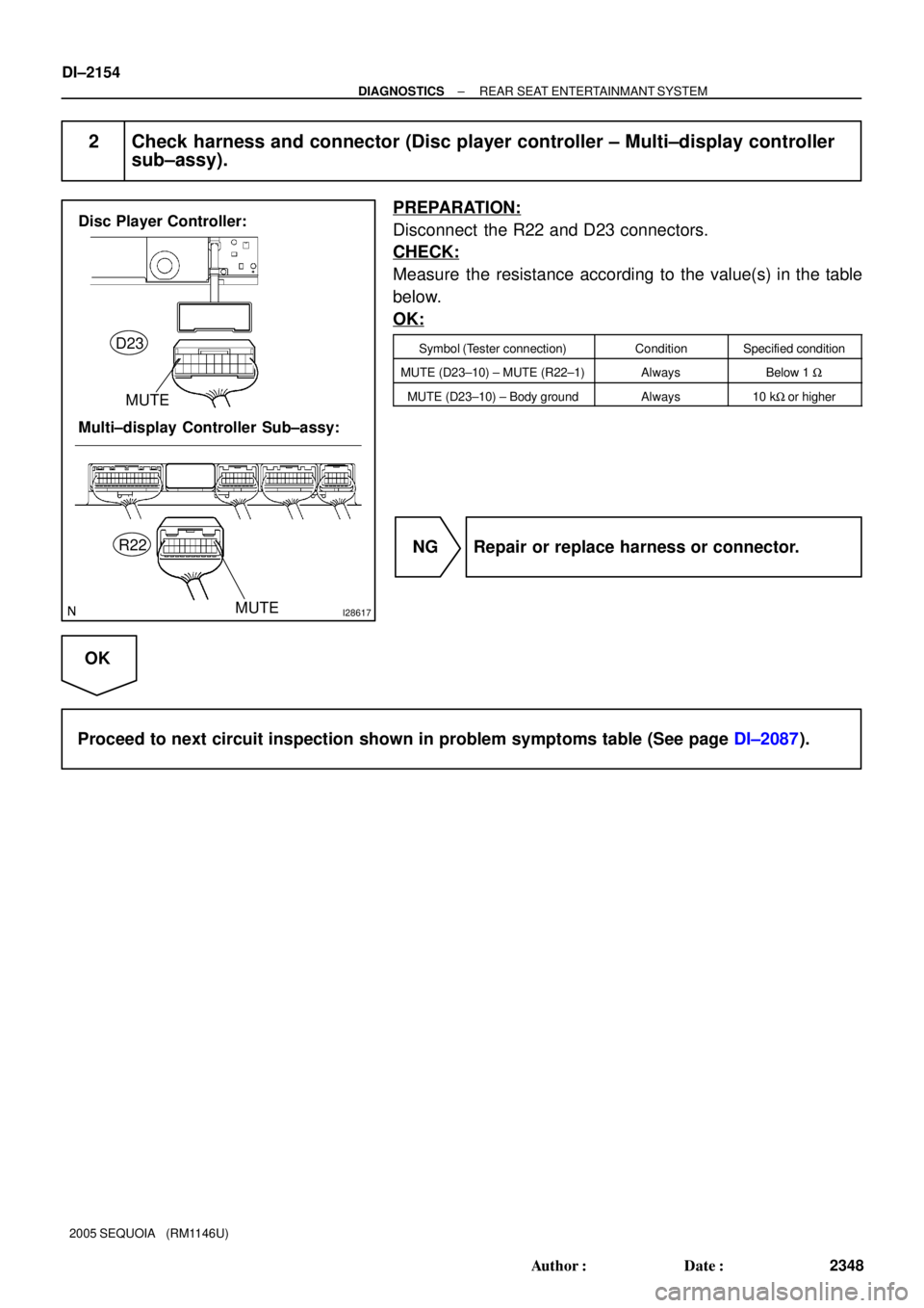
Disc Player Controller:
Multi±display Controller Sub±assy:MUTE
MUTE
D23
R22
DI±2154
± DIAGNOSTICSREAR SEAT ENTERTAINMANT SYSTEM
2348 Author�: Date�:
2005 SEQUOIA (RM1146U)
2 Check harness and connector (Disc player controller ± Multi±display controller
sub±assy).
PREPARATION:
Disconnect the R22 and D23 connectors.
CHECK:
Measure the resistance according to the value(s) in the table
below.
OK:
Symbol (Tester connection)ConditionSpecified condition
MUTE (D23±10) ± MUTE (R22±1)AlwaysBelow 1 W
MUTE (D23±10) ± Body groundAlways10 kW or higher
NG Repair or replace harness or connector.
OK
Proceed to next circuit inspection shown in problem symptoms table (See page DI±2087).
Page 2358 of 4323
I28321I28327
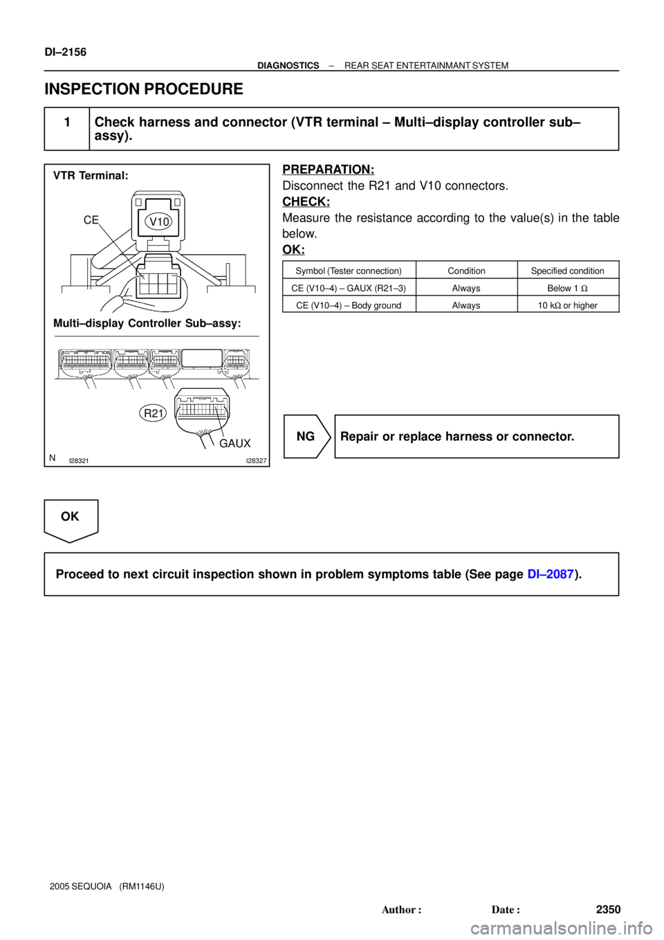
VTR Terminal:
Multi±display Controller Sub±assy:
GAUX
CE
V10
R21
DI±2156
± DIAGNOSTICSREAR SEAT ENTERTAINMANT SYSTEM
2350 Author�: Date�:
2005 SEQUOIA (RM1146U)
INSPECTION PROCEDURE
1 Check harness and connector (VTR terminal ± Multi±display controller sub±
assy).
PREPARATION:
Disconnect the R21 and V10 connectors.
CHECK:
Measure the resistance according to the value(s) in the table
below.
OK:
Symbol (Tester connection)ConditionSpecified condition
CE (V10±4) ± GAUX (R21±3)AlwaysBelow 1 W
CE (V10±4) ± Body groundAlways10 kW or higher
NG Repair or replace harness or connector.
OK
Proceed to next circuit inspection shown in problem symptoms table (See page DI±2087).
Page 2360 of 4323
I28723
DI±2158
± DIAGNOSTICSREAR SEAT ENTERTAINMANT SYSTEM
2352 Author�: Date�:
2005 SEQUOIA (RM1146U)
3 Clean the infrared ray emitting portion.
PREPARATION:
Clean the infrared ray emitting portion.
CHECK:
(a) Clean the infrared ray emitting portion on the television
display assy.
(b) Check whether the same malfunction occurs.
OK:
The function returns to normal.
OK End.
NG
4 Replace switch assy.
CHECK:
Replace the switch assy and check if it operates normally.
OK:
Normal operation.
OK End.
NG
Proceed to next circuit inspection shown in problem symptoms table (See page DI±2087).
Page 2361 of 4323
DIDBO±01
± DIAGNOSTICSNAVIGATION SYSTEM
DI±2159
2353 Author�: Date�:
2005 SEQUOIA (RM1146U)
NAVIGATION SYSTEM
PRECAUTION
NOTICE:
When disconnecting the battery terminal, initialize the following system after the terminal is recon-
nected.
System NameSee Page
Back Door Power Window Control SystemBE±77
Page 2368 of 4323

I28189
Navigation performed even where the
GPS radio wave does not reach.
� In a tunnel
� In an indoor parking lot
� Between tall buildings
� Under an overpass
� On a forest or tree±lined path
Autonomous navigation
Autonomous navigation and
GPS navigationGPS satellite DI±2166
± DIAGNOSTICSNAVIGATION SYSTEM
2360 Author�: Date�:
2005 SEQUOIA (RM1146U)Operation
Description
Vehicle Position Calculation
The navigation ECU calculates the current vehicle position (direction and current
position) using the direction deviation signal from the gyro sensor and the running
distance signal from the vehicle speed sensor and creates the driving route.
Map Display processingThe navigation ECU displays the vehicle track on the map by processing the ve-
hicle position data, vehicle running track, and map data from the map disc.
Map MatchingThe map data from the map disc is compared to the vehicle position and running
track data. Then, the vehicle position is matched with the nearest road.
GPS Correction
The vehicle position is matched to the position measured by GPS. Then, the mea-
surement position data from the GPS unit is compared with the vehicle position and
running track data. If the position is widely different, the GPS measurement position
is used.
Distance Correction
The running distance signal from the vehicle speed sensor includes the error
caused by tire wear and slippage between the tires and road surface. Distance
correction is performed to account for this. The navigation ECU automatically off-
sets the running distance signal to make up for the difference between it and the
distance data of the map. The offset is automatically updated.
HINT:
The combination of autonomous and GPS navigation makes it possible to display the vehicle position even
when the vehicle is in places where the GPS radio wave cannot receive a signal. When only autonomous
navigation is used, however, the mapping accuracy may slightly decline.