Page 2315 of 4323

INSPECTION PROCEDURE
1 Inspect disc player controller (")
I28664
+BACC
GND
Disc Player Controller:
D23
± DIAGNOSTICSREAR SEAT ENTERTAINMANT SYSTEM
DI±2113
2307 Author�: Date�:
2005 SEQUOIA (RM1146U)
INSPECTION PROCEDURE
1 Inspect disc player controller (+B, ACC, GND).
PREPARATION:
Disconnect the D23 connector.
CHECK:
Measure the resistance according to the value(s) in the table
below.
OK:
Symbol (Tester connection)ConditionSpecified condition
GND (D23±16) ± Body groundAlwaysBelow 1 W
CHECK:
Measure the voltage according to the value(s) in the table be-
low.
OK:
Symbol (Tester connection)ConditionSpecified condition
+B (D23±20) ± GND (D23±16)Always10 to 14 V
ACC (D23±19) ± GND (D23±16)Ignition SW ACC10 to 14 V
NG Go to step 3.
OK
2 Check problem symptoms table.
CHECK:
Check the problem symptoms table.
RESULT:
All possible suspected areas have been inspectedGo to step A
Possible suspected areas still existGo to step B
B Proceed to next circuit inspection shown in
problem symptoms table or diagnostic trouble
code chart (See page DI±2087 or DI±2103).
A
Replace disc player controller.
Page 2318 of 4323

I28616
Television Display Assy:
Multi±display Controller Sub±assy:VG
VR
SYNC
VG2 VR2
SYN2
R25
R21
R
G
B
R2
G2
B2
DI±2116
± DIAGNOSTICSREAR SEAT ENTERTAINMANT SYSTEM
2310 Author�: Date�:
2005 SEQUOIA (RM1146U)
INSPECTION PROCEDURE
1 Display check mode (Color bar check).
CHECK:
Enter display check mode (See page DI±2085).
Start the diagnosis system and perform the display color bar check in display check mode.
OK:
The check result is normal.
OK Adjust display color.
NG
2 Check harness and connector (Multi±display controller sub±assy ± Television
display assy).
PREPARATION:
Disconnect the R21 and R25 connectors.
CHECK:
Measure the resistance according to the value(s) in the table
below.
OK:
Symbol (Tester connection)ConditionSpecified condition
VG (R25±11) ± VG2 (R21±18)AlwaysBelow 1 W
VR (R25±12) ± VR2 (R21±17)AlwaysBelow 1 W
SYNC (R25±13) ± SYN2 (R21±16)AlwaysBelow 1 W
B (R25±14) ± B2 (R21±15)AlwaysBelow 1 W
G (R25±15) ± G2 (R21±14)AlwaysBelow 1 W
R (R25±16) ± R2 (R21±13)AlwaysBelow 1 W
VG (R25±11)± Body groundAlways10 kW or higher
VR (R25±12) ± Body groundAlways10 kW or higher
SYNC (R25±13) ± Body groundAlways10 kW or higher
B (R25±14) ± Body groundAlways10 kW or higher
G (R25±15) ± Body groundAlways10 kW or higher
R (R25±16) ± Body groundAlways10 kW or higher
NG Repair or replace harness or connector.
OK
Proceed to next circuit inspection shown in problem symptoms table (See page DI±2087).
Page 2320 of 4323
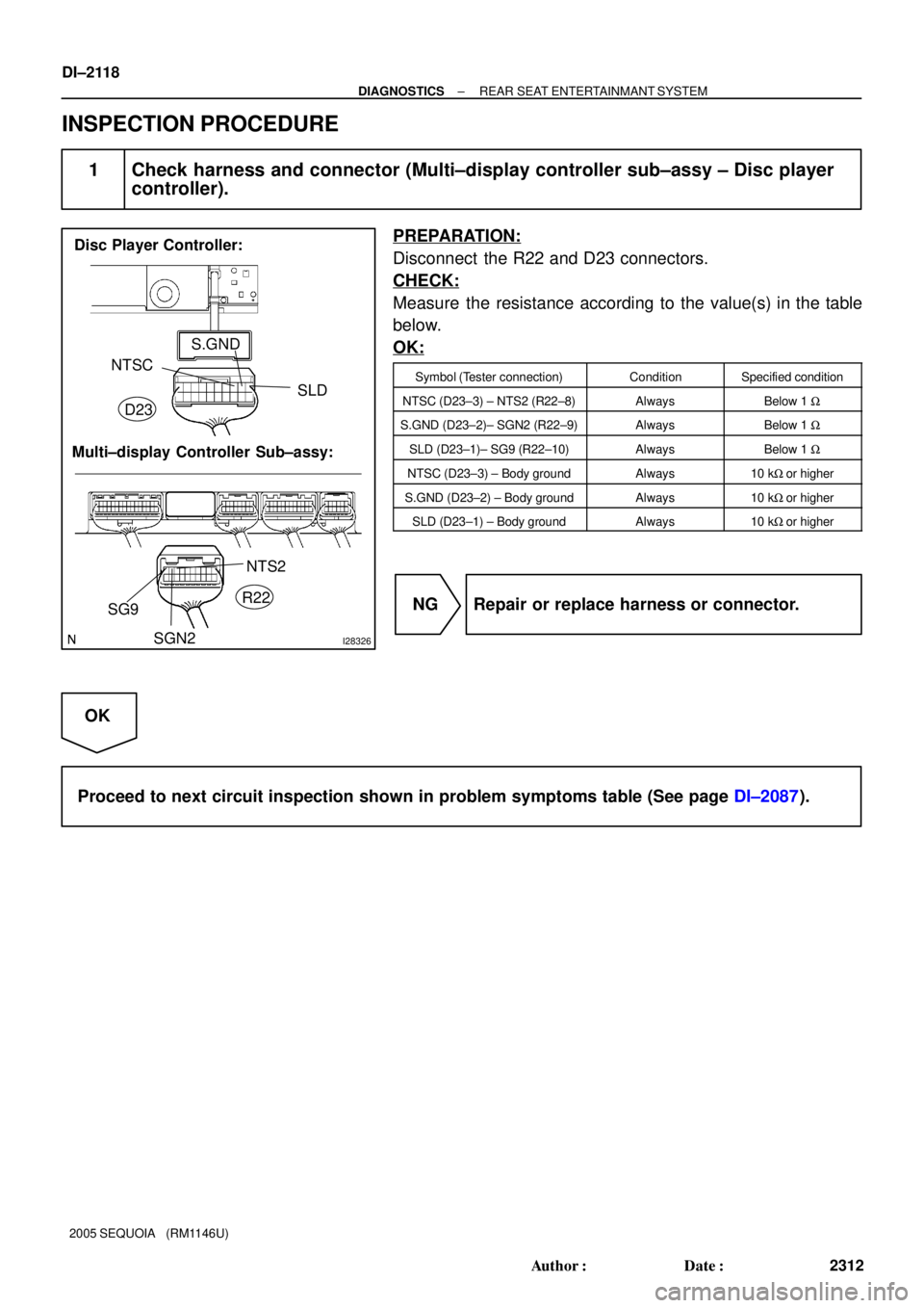
I28326
Disc Player Controller:
Multi±display Controller Sub±assy:SLD S.GND
NTSC
NTS2
SGN2 SG9
D23
R22
DI±2118
± DIAGNOSTICSREAR SEAT ENTERTAINMANT SYSTEM
2312 Author�: Date�:
2005 SEQUOIA (RM1146U)
INSPECTION PROCEDURE
1 Check harness and connector (Multi±display controller sub±assy ± Disc player
controller).
PREPARATION:
Disconnect the R22 and D23 connectors.
CHECK:
Measure the resistance according to the value(s) in the table
below.
OK:
Symbol (Tester connection)ConditionSpecified condition
NTSC (D23±3) ± NTS2 (R22±8)AlwaysBelow 1 W
S.GND (D23±2)± SGN2 (R22±9)AlwaysBelow 1 W
SLD (D23±1)± SG9 (R22±10)AlwaysBelow 1 W
NTSC (D23±3) ± Body groundAlways10 kW or higher
S.GND (D23±2) ± Body groundAlways10 kW or higher
SLD (D23±1) ± Body groundAlways10 kW or higher
NG Repair or replace harness or connector.
OK
Proceed to next circuit inspection shown in problem symptoms table (See page DI±2087).
Page 2322 of 4323
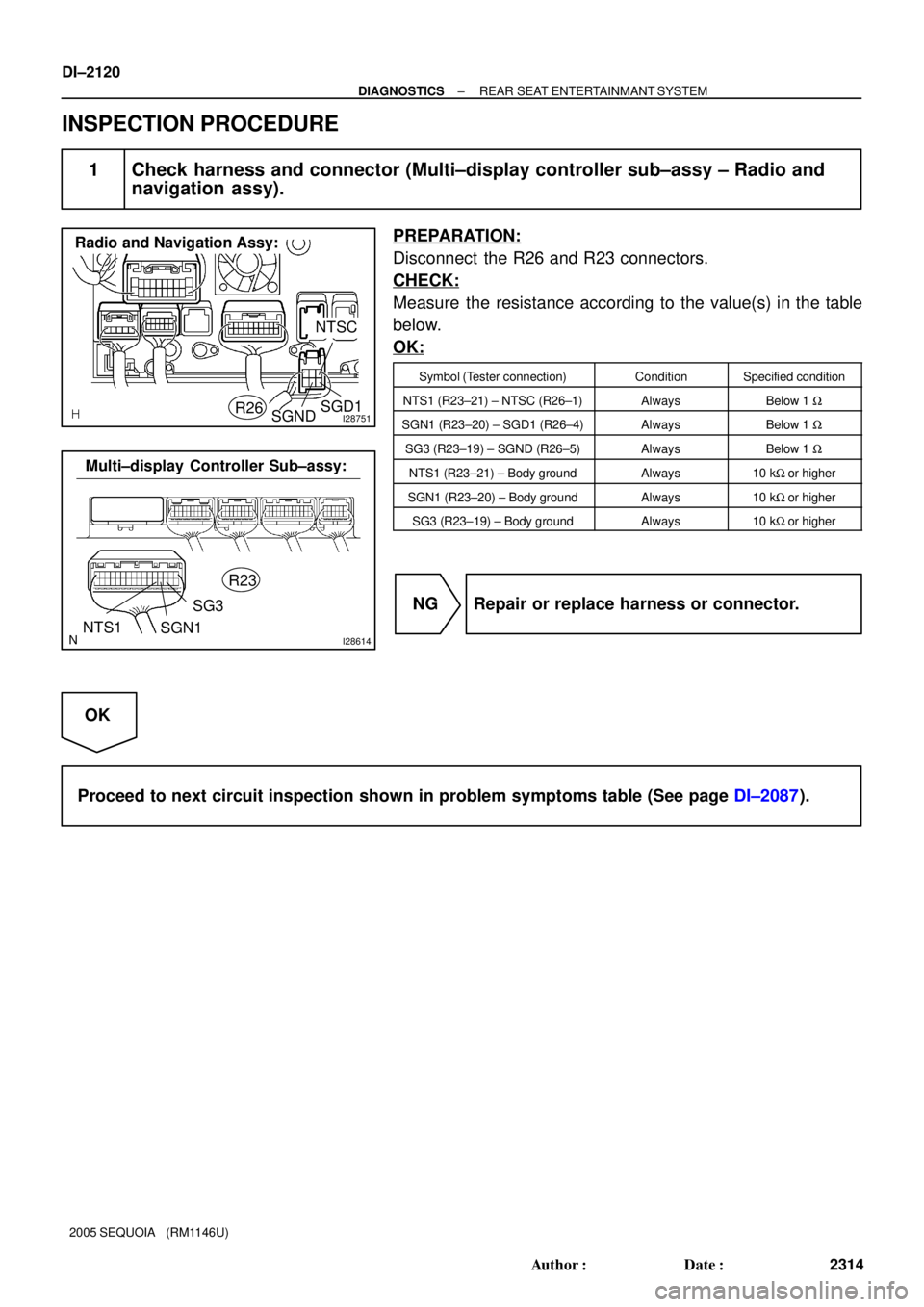
I28751
NTSC
R26
Radio and Navigation Assy:
SGNDSGD1
I28614NTS1R23
Multi±display Controller Sub±assy:
SGN1SG3
DI±2120
± DIAGNOSTICSREAR SEAT ENTERTAINMANT SYSTEM
2314 Author�: Date�:
2005 SEQUOIA (RM1146U)
INSPECTION PROCEDURE
1 Check harness and connector (Multi±display controller sub±assy ± Radio and
navigation assy).
PREPARATION:
Disconnect the R26 and R23 connectors.
CHECK:
Measure the resistance according to the value(s) in the table
below.
OK:
Symbol (Tester connection)ConditionSpecified condition
NTS1 (R23±21) ± NTSC (R26±1)AlwaysBelow 1 W
SGN1 (R23±20) ± SGD1 (R26±4)AlwaysBelow 1 W
SG3 (R23±19) ± SGND (R26±5)AlwaysBelow 1 W
NTS1 (R23±21) ± Body groundAlways10 kW or higher
SGN1 (R23±20) ± Body groundAlways10 kW or higher
SG3 (R23±19) ± Body groundAlways10 kW or higher
NG Repair or replace harness or connector.
OK
Proceed to next circuit inspection shown in problem symptoms table (See page DI±2087).
Page 2324 of 4323
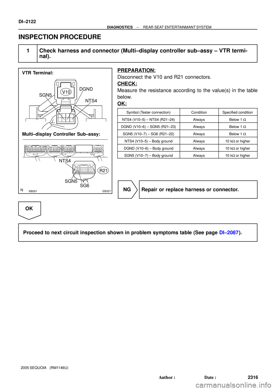
I28321I28327
VTR Terminal:
Multi±display Controller Sub±assy:
NTS4
SGN5
SG6
SGN5DGND
NTS4 V10
R21
DI±2122
± DIAGNOSTICSREAR SEAT ENTERTAINMANT SYSTEM
2316 Author�: Date�:
2005 SEQUOIA (RM1146U)
INSPECTION PROCEDURE
1 Check harness and connector (Multi±display controller sub±assy ± VTR termi-
nal).
PREPARATION:
Disconnect the V10 and R21 connectors.
CHECK:
Measure the resistance according to the value(s) in the table
below.
OK:
Symbol (Tester connection)ConditionSpecified condition
NTS4 (V10±5) ± NTS4 (R21±24)AlwaysBelow 1 W
DGND (V10±6) ± SGN5 (R21±23)AlwaysBelow 1 W
SGN5 (V10±7) ± SG6 (R21±22)AlwaysBelow 1 W
NTS4 (V10±5) ± Body groundAlways10 kW or higher
DGND (V10±6) ± Body groundAlways10 kW or higher
SGN5 (V10±7) ± Body groundAlways10 kW or higher
NG Repair or replace harness or connector.
OK
Proceed to next circuit inspection shown in problem symptoms table (See page DI±2087).
Page 2326 of 4323

I28740
Radio Receiver Assy
Wire Harness View:
L+
S±GND
L±
R+R±R20
I28614
R23
L+ SG1
R±L±
R+
Multi±display Controller Sub±assy:
DI±2124
± DIAGNOSTICSREAR SEAT ENTERTAINMANT SYSTEM
2318 Author�: Date�:
2005 SEQUOIA (RM1146U)
INSPECTION PROCEDURE
1 Check harness and connector (Radio receiver assy ± Multi±display controller
sub±assy).
PREPARATION:
Disconnect the R20 and R23 connectors.
CHECK:
Measure the resistance according to the value(s) in the table
below.
OK:
Symbol (Tester connection)ConditionSpecified condition
L+ (R20±4) ± L+ (R23±8)AlwaysBelow 1 W
L± (R20±5) ± L± (R23±7)AlwaysBelow 1 W
R+ (R20±2) ± R+ (R23±10)AlwaysBelow 1 W
R± (R20±3) ± R± (R23±9)AlwaysBelow 1 W
S±GND (R20±1) ± SG1 (R23±11)AlwaysBelow 1 W
L+ (R20±4) ± Body groundAlways10 kW or higher
L± (R20±5) ± Body groundAlways10 kW or higher
R+ (R20±2) ± Body groundAlways10 kW or higher
R± (R20±3) ± Body groundAlways10 kW or higher
S±GND (R20±1) ± Body groundAlways10 kW or higher
NG Repair or replace harness or connector.
OK
Proceed to next circuit inspection shown in problem symptoms table (See page DI±2087).
Page 2328 of 4323

I28612
Radio and Navigation Assy
Wire Harness View:
R28
CDL+CDR±
CSLDCDL±
CDR+
I28614
R23
L+ SG1
R±L±
R+
Multi±display Controller Sub±assy:
DI±2126
± DIAGNOSTICSREAR SEAT ENTERTAINMANT SYSTEM
2320 Author�: Date�:
2005 SEQUOIA (RM1146U)
INSPECTION PROCEDURE
1 Check harness and connector (Radio and navigation assy ± Multi±display con-
troller sub±assy).
PREPARATION:
Disconnect the R23 and R28 connectors.
CHECK:
Measure the resistance according to the value(s) in the table
below.
OK:
Symbol (Tester connection)ConditionSpecified condition
CDL+ (R28±4) ± L+ (R23±8)AlwaysBelow 1 W
CDL± (R28±5) ± L± (R23±7)AlwaysBelow 1 W
CDR+ (R28±2) ± R+ (R23±10)AlwaysBelow 1 W
CDR± (R28±3) ± R± (R23±9)AlwaysBelow 1 W
CSLD (R28±1) ± SG1 (R23±11)AlwaysBelow 1 W
CDL+ (R28±4) ± Body groundAlways10 kW or higher
CDL± (R28±5) ± Body groundAlways10 kW or higher
CDR+ (R28±2) ± Body groundAlways10 kW or higher
CDR± (R28±3) ± Body groundAlways10 kW or higher
CSLD (R28±1) ± Body groundAlways10 kW or higher
NG Repair or replace harness or connector.
OK
Proceed to next circuit inspection shown in problem symptoms table (See page DI±2087).
Page 2330 of 4323

I28618
Multi±display Controller Sub±assy:
R±L±
R±L+
R±R± R±R+
Radio Receiver Assy:
SG2
RSR+RSL+
RSR±
RSL±
SLD1
R19
R23
DI±2128
± DIAGNOSTICSREAR SEAT ENTERTAINMANT SYSTEM
2322 Author�: Date�:
2005 SEQUOIA (RM1146U)
INSPECTION PROCEDURE
1 Check harness and connector (Radio receiver assy ± Multi±display controller
sub±assy).
PREPARATION:
Disconnect the R23 and R19 connectors.
CHECK:
Measure the resistance according to the value(s) in the table
below.
OK:
Symbol (Tester connection)ConditionSpecified condition
RSR+ (R19±15) ±
R±R+ (R23±26)AlwaysBelow 1 W
RSR± (R19±16) ±
R±R± (R23±25)AlwaysBelow 1 W
RSL+ (R19±17) ±
R±L+ (R23±24)AlwaysBelow 1 W
RSL± (R19±18) ±
R±L± (R23±23)AlwaysBelow 1 W
SLD1 (R19±14) ± SG2 (R23±27)AlwaysBelow 1 W
RSR+ (R19±15) ± Body groundAlways10 kW or higher
RSR± (R19±16) ± Body groundAlways10 kW or higher
RSL+ (R19±17) ± Body groundAlways10 kW or higher
RSL± (R19±18) ± Body groundAlways10 kW or higher
SLD1 (R19±14) ± Body groundAlways10 kW or higher
NG Repair or replace harness or connector.
OK
Proceed to next circuit inspection shown in problem symptoms table (See page DI±2087).