Page 2250 of 4323
DIDAI±01
Vehicle brought into a workshop
4. Check the diagnostic trouble codes
DTC is not output (Go to step 6)
5. Diagnostic trouble code chart
Go to step 7
7. Circuit inspection and part inspection
10. Perform confirmation test
ENDItems inside
are titles of pages in this manual,
with the page number in the bottom portion. See
the pages for detailed explanations.
P. DI±2053
P. DI±2058 ± DI±2076 P. DI±1979, DI±2203 1. Customer problem analysis
P. DI±2049
2. Problem Symptoms Confirmation
Symptom does
not occur
Malfunction
code
6. Problem symptoms table
P. DI±2050
8. Identification of problem
Symptom occursGo to step 4
3. Symptom Simulation
P. IN±24
9. Repair or replace
Normal system
code DI±2048
± DIAGNOSTICSREAR SEAT AUDIO SYSTEM
2242 Author�: Date�:
2005 SEQUOIA (RM1146U)
HOW TO PROCEED WITH TROUBLESHOOTING
Page 2252 of 4323

PROBLEM SYMPTOMS TABLE
RSA SYSTEM
SymptomSuspected AreasSee page
RSA system cannot be powered.1. P")
DIDAK±01
DI±2050
± DIAGNOSTICSREAR SEAT AUDIO SYSTEM
2244 Author�: Date�:
2005 SEQUOIA (RM1146U)
PROBLEM SYMPTOMS TABLE
RSA SYSTEM
SymptomSuspected AreasSee page
RSA system cannot be powered.1. Power source circuit (rear seat controller assy)DI±2058
Quality of sound from wireless headphone is poor or no sound
can be heard.
1. Power source circuit (rear seat controller assy)
2. Mute signal circuit (to rear seat audio controller)
3. Sound signal circuit (to rear seat audio controller)
4. Rear seat audio controllerDI±2058
DI±2066
DI±2070
±
Quality of sound from headphone connected to headphone termi-
nal is poor or no sound can be heard.
1. Power source circuit (rear seat controller assy)
2. Mute signal circuit (to rear seat audio controller)
3. Sound signal circuit (Rear seat audio controller ± head-
phone terminal)
4. Sound signal circuit (Radio receiver assy / radio and
navigation assy ± rear seat audio controller)DI±2058
DI±2066
DI±2073
DI±2070
REMOTE CONTROL
SymptomSuspected AreasSee page
A remote control system does not operate.
1. Power source circuit (rear seat controller assy)
2. A remote control system does not operate
3. AVC±LAN circuitDI±2058
DI±2076
DI±2061
Page 2255 of 4323

DTC CHECK / CLEAR
1. DIAGNOSIS CHECK
HINT:
RSA system inspects the devices con")
DIDAH±01
I28317
Switch Assy:
± DIAGNOSTICSREAR SEAT AUDIO SYSTEM
DI±2053
2247 Author�: Date�:
2005 SEQUOIA (RM1146U)
DTC CHECK / CLEAR
1. DIAGNOSIS CHECK
HINT:
RSA system inspects the devices consisting of Sub AVC±LAN
on the rear seat audio controller assy.
(a) Starting Main AVC±LAN (See page DI±1974, DI±2191).
HINT:
�As starting Main AVC±LAN to operate the diagnosis
mode, Sub AVC±LAN also automatically enters the diag-
nosis mode. Perform the diagnosis mode operation on
the rear seat audio controller assy.
�Use a switch assy to operate diagnosis mode.
(b) Service Check Screen
Reference
In the service check mode, the system check and
the diagnosis memory check are performed, and
the check results are displayed in ascending order
of the device codes (physical address).
TermsMeaning
Component code
(Physical address)Three±digit code (In hexadecimal) given to each device
comprising AVC±LAN. Corresponding to its function, individ-
ual symbol is provided.
Logical addressTwo±digit code (In hexadecimal) given to each function and
device unit in each device comprising AVC±LAN.
(c) Finishing Diagnosis Mode (See page DI±1974,
DI±2191).
(d) Element Check Mode
After the diagnosis start±up, the system enters the ele-
ment check mode. Check that the all elements come on.
Page 2259 of 4323
± DIAGNOSTICSREAR SEAT AUDIO SYSTEM
DI±2057
2251 Author�: Date�:
2005 SEQUOIA (RM1146U)
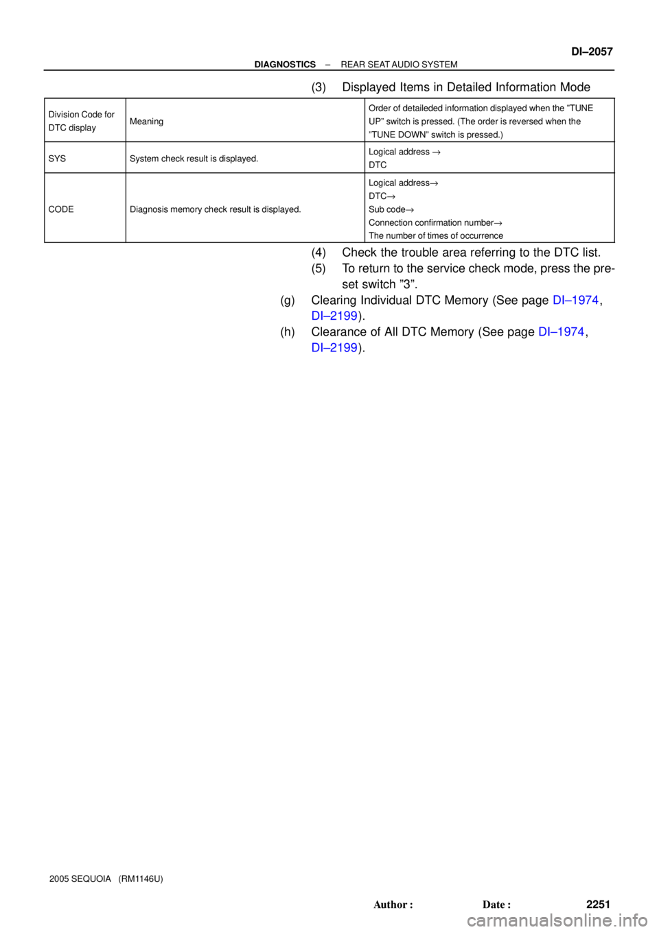
(3) Displayed Items in Detailed Information Mode
Division Code for
DTC displayMeaning
Order of detaileded information displayed when the ºTUNE
UPº switch is pressed. (The order is reversed when the
ºTUNE DOWNº switch is pressed.)
SYSSystem check result is displayed.Logical address "
DTC
CODEDiagnosis memory check result is displayed.
Logical address"
DTC"
Sub code"
Connection confirmation number"
The number of times of occurrence
(4) Check the trouble area referring to the DTC list.
(5) To return to the service check mode, press the pre-
set switch º3º.
(g) Clearing Individual DTC Memory (See page DI±1974,
DI±2199).
(h) Clearance of All DTC Memory (See page DI±1974,
DI±2199).
Page 2262 of 4323
DI±2060
± DIAGNOSTICSREAR SEAT AUDIO SYSTEM
2254 Author�: Date�:
2005 SEQUOIA (RM1146U)
2 Check problem symptoms table.
CHECK:
Check the problem symptoms table.
RESULT:
All possible suspected areas have been inspected.Go to step A
Possible suspected areas still exist.Go to step B
B Proceed to next circuit inspection shown in
problem symptoms table (See page DI±2050).
A
Replace rear seat audio controller.
Page 2264 of 4323
I28599I28773
w/ Navigation:
Radio and Navigation AssyRear Seat Audio Controller
R27
Stereo Component Amplifier AssyTX± TX+
S10 ID2
LG
LG
V
P L 9
10
5
1522
R24
23
TX± TX+
ATX± ATX+27 26
TX± TX+ 20
19 R30LGID2 R24
S10 R30 R27
DI±2062
± DIAGNOSTICSREAR SEAT AUDIO SYSTEM
2256 Author�: Date�:
2005 SEQUOIA (RM1146U)
INSPECTION PROCEDURE
1 Service check mode (Rear seat audio controller).
CHECK:
Start the diagnosis system and read the check result for the rear seat audio controller (See page DI±1974,
DI±2191).
RESULT:
ºNCONº is displayed or result is not displayed (w/ naviga-
tion)Go to step A
ºNCONº is displayed or result is not displayed (w/o naviga-
tion)Go to step B
ºNCONº is displayed or result is not displayed (DSP AMP)Go to step C
ºGOODº is displayedGo to step D
B Go to step 3.
C Go to step 4.
D Replace radio and navigation assy or radio re-
ceiver assy.
A
Page 2269 of 4323
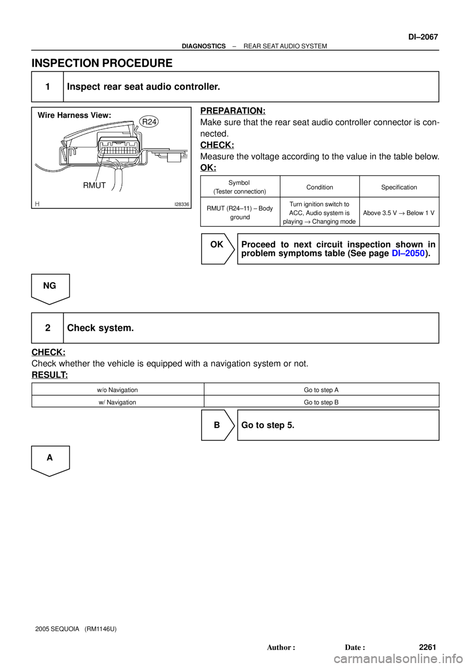
I28336
RMUT
R24Wire Harness View:
± DIAGNOSTICSREAR SEAT AUDIO SYSTEM
DI±2067
2261 Author�: Date�:
2005 SEQUOIA (RM1146U)
INSPECTION PROCEDURE
1 Inspect rear seat audio controller.
PREPARATION:
Make sure that the rear seat audio controller connector is con-
nected.
CHECK:
Measure the voltage according to the value in the table below.
OK:
Symbol
(Tester connection)ConditionSpecification
RMUT (R24±11) ±Body
groundTurn ignition switch to
ACC, Audio system is
playing "Changing mode
Above 3.5 V " Below 1 V
OK Proceed to next circuit inspection shown in
problem symptoms table (See page DI±2050).
NG
2 Check system.
CHECK:
Check whether the vehicle is equipped with a navigation system or not.
RESULT:
w/o NavigationGo to step A
w/ NavigationGo to step B
B Go to step 5.
A
Page 2274 of 4323

I28606
Radio Receiver Assy
Wire Harness View:
R19
RSR+
RSR±
RSL+ SLD1
RSL±
I28750
Radio and Navigation Assy
Wire Harness View:
R27
R±L+
R±L±
R±R±R±R+
RSLD
I28337R±R+
Rear Seat Audio Controller
Wire Harness View:
R±R±
R±L+ SG1
R±L±
R24
DI±2072
± DIAGNOSTICSREAR SEAT AUDIO SYSTEM
2266 Author�: Date�:
2005 SEQUOIA (RM1146U)
INSPECTION PROCEDURE
1 Check harness and connector (Radio receiver assy / radio and navigation assy ±
Rear seat audio controller).
PREPARATION:
Disconnect the radio receiver assy or radio and navigation con-
nector and rear seat audio controller connector.
CHECK:
Measure the resistance according to the values in the table be-
low.
OK:
Symbol (Tester connection)Specified condition
R±R+ (R24±9) ± R±R+ (R27±15) (*1), RSR+ (R19±15) (*2)Below 1 W
R±R± (R24±8) ± R±R± (R27±16) (*1), RSR± (R19±16) (*2)Below 1 W
R±L+ (R24±7) ± R±L+ (R27±17) (*1), RSL+ (R19±17) (*2)Below 1 W
R±L± (R24±6) ± R±L± (R27±18) (*1), RSL± (R19±18) (*2)Below 1 W
SG1 (R24±10) ± RSLD (R27±14), SLD1 (R19±14)Below 1 W
R±R+ (R24±9) ± Body ground10 kW or higher
R±R± (R24±8) ± Body ground10 kW or higher
R±L+ (R24±7) ± Body ground10 kW or higher
R±L± (R24±6) ± Body ground10 kW or higher
SG1 (R24±10) ± Body ground10 kW or higher
*1: w/ Navigation System
*2: w/o Navigation System
NG Repair or replace harness or connector.
OK
Proceed to next circuit inspection shown in problem symptoms table (See page DI±2050).

5. Diagnostic trouble code chart
Go to step 7
7. Circuit inspection and part inspection")