Page 2150 of 4323
DI±1948
± DIAGNOSTICSMULTIPLEX COMMUNICATION SYSTEM
2142 Author�: Date�:
2005 SEQUOIA (RM1146U)
INSPECTION PROCEDURE
1 Check power seat control system (w/ driving position memory).
CHECK:
Check the operation of the power seat.
OK:
The power seat control system operates normally.
NG Go to power source circuit (See page DI±1514).
OK
2 Check wire harness (Memory seat ECU & switch ± combination meter).
PREPARATION:
Disconnect connector ºM6º of the memory seat ECU and ºC5º of the combination meter.
CHECK:
Measure the resistance according to the values in the table below.
OK:
Tester connection (Symbols)ConditionSpecified condition
M6±1 (MPX1) ± C5±30AlwaysBelow 1 W
M6±1 (MPX1) ± Body groundAlways10 kW or higher
NG Repair or replace wire harness or connector.
OK
Replace memory seat ECU & switch.
If the problem recurs even after replacement, replace the body ECU.
Page 2153 of 4323
± DIAGNOSTICSMULTIPLEX COMMUNICATION SYSTEM
DI±1951
2145 Author�: Date�:
2005 SEQUOIA (RM1146U)
INSPECTION PROCEDURE
1 Check sliding roof ECU.
CHECK:
Check that the operation of the sliding roof function is normal.
HINT:
The operating condition of the sliding roof ECU CPU can be diagnosed with this check.
OK:
The sliding roof operates normally.
NG Go to power source circuit (See page DI±1668).
OK
2 Check wire harness and connector (Sliding roof control ECU ± body ECU).
PREPARATION:
Disconnect connector ºB7º of the body ECU and connector ºS19º of the sliding roof ECU.
CHECK:
Measure the resistance according to the values in the table below.
OK:
Tester connection (Symbols)ConditionSpecified condition
S19±2 (MPX1) ± B7±20 (MPX3)AlwaysBelow 1 W
S19±2 (MPX1) ± Body groundAlways10 kW or higher
NG Repair or replace wire harness.
OK
Replace the sliding roof ECU.
If the problem recurs even after replacement, replace the body ECU.
Page 2157 of 4323
DID9J±01
± DIAGNOSTICSAUDIO SYSTEM
DI±1955
2149 Author�: Date�:
2005 SEQUOIA (RM1146U)
AUDIO SYSTEM
PRECAUTION
NOTICE:
When disconnect the battery terminal, initialize the following systems after the terminal is recon-
nected.
System NameSee Page
Back Door Power Window Control SystemBE±77
Page 2164 of 4323

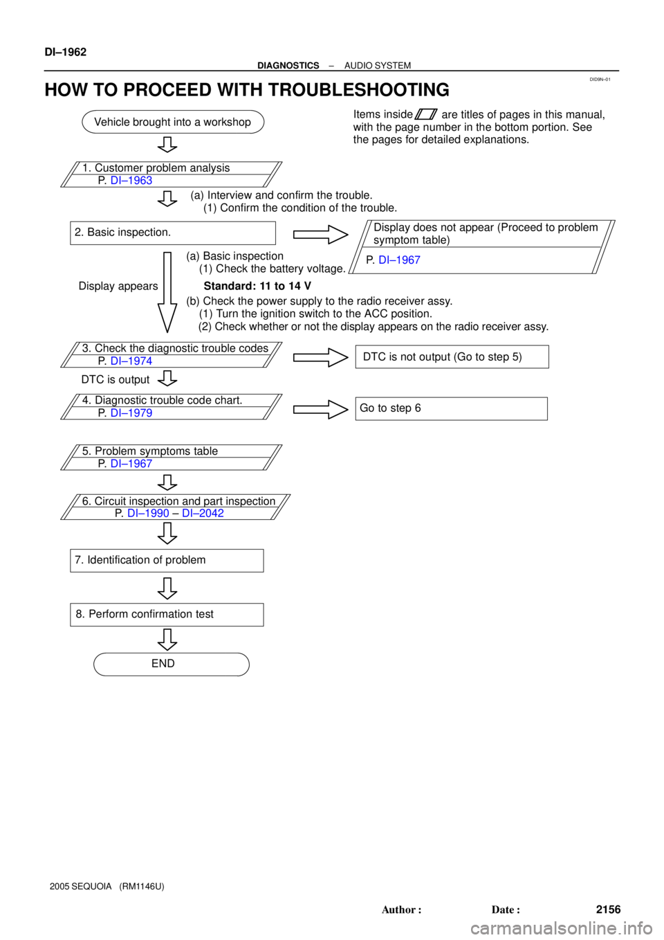
DID9N±01
Vehicle brought into a workshop
3. Check the diagnostic trouble codes
DTC is not output (Go to step 5)
4. Diagnostic trouble code chart.
Go to step 6
6. Circuit inspection and part inspection
8. Perform confirmation test
ENDItems inside
are titles of pages in this manual,
with the page number in the bottom portion. See
the pages for detailed explanations.
P. DI±1974
P. DI±1990 ± DI±2042 P. DI±1979 1. Customer problem analysis
P. DI±1963
(a) Interview and confirm the trouble.
(1) Confirm the condition of the trouble.
(a) Basic inspection
(1) Check the battery voltage. 2. Basic inspection.
Standard: 11 to 14 V
(b) Check the power supply to the radio receiver assy.
(1) Turn the ignition switch to the ACC position.
(2) Check whether or not the display appears on the radio receiver assy.Display does not appear (Proceed to problem
symptom table)
Display appears
DTC is output
5. Problem symptoms table
P. DI±1967
7. Identification of problem
P. DI±1967 DI±1962
± DIAGNOSTICSAUDIO SYSTEM
2156 Author�: Date�:
2005 SEQUOIA (RM1146U)
HOW TO PROCEED WITH TROUBLESHOOTING
Page 2169 of 4323

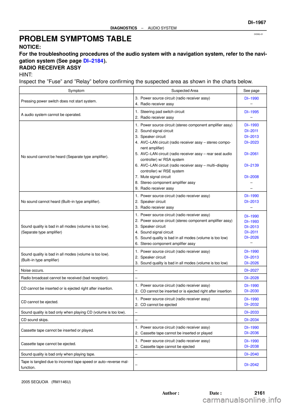
DID9Q±01
± DIAGNOSTICSAUDIO SYSTEM
DI±1967
2161 Author�: Date�:
2005 SEQUOIA (RM1146U)
PROBLEM SYMPTOMS TABLE
NOTICE:
For the troubleshooting procedures of the audio system with a navigation system, refer to the navi-
gation system (See page DI±2184).
RADIO RECEIVER ASSY
HINT:
Inspect the ºFuseº and ºRelayº before confirming the suspected area as shown in the charts below.
SymptomSuspected AreaSee page
Pressing power switch does not start system.3. Power source circuit (radio receiver assy)
4. Radio receiver assyDI±1990
±
A audio system cannot be operated.1. Steering pad switch circuit
2. Radio receiver assyDI±1995
±
No sound cannot be heard (Separate type amplifier).
1. Power source circuit (stereo component amplifier assy)
2. Sound signal circuit
3. Speaker circuit
4. AVC±LAN circuit (radio receiver assy ± stereo compo-
nent amplifier)
5. AVC±LAN circuit (radio receiver assy ± rear seat audio
controller) w/ RSA system
6. AVC±LAN circuit (radio receiver assy ± multi±display
controller) w/ RSE system
7. Mute signal circuit
8. Stereo component amplifier assy
9. Radio receiver assyDI±1993
DI±2011
DI±2013
DI±2023
DI±2061
DI±2139
DI±2008
±
±
No sound cannot heard (Built±in type amplifier).
1. Power source circuit (radio receiver assy)
2. Speaker circuit
3. Radio receiver assyDI±1990
DI±2013
±
Sound quality is bad in all modes (volume is too low).
(Separate type amplifier)
1. Power source circuit (radio receiver assy)
2. Power source circuit (stereo component amplifier assy)
3. Speaker circuit
4. Sound signal circuit
5. Sound quality is bad in all modes (volume is too low)
6. Stereo component amplifier assyDI±1990
DI±1993
DI±2013
DI±2011
DI±2026
±
Sound quality is bad in all modes (volume is too low).
(Built±in type amplifier)1. Power source circuit (radio receiver assy)
2. Speaker circuit
3. Sound quality is bad in all modes (volume is too low)DI±1990
DI±2013
DI±2026
Noise occurs.±DI±2027
Radio broadcast cannot be received (bad reception).±DI±2028
CD cannot be inserted or is ejected right after insertion.1. Power source circuit (radio receiver assy)
2. CD cannot be inserted or is ejected right after insertionDI±1990
DI±2030
CD cannot be ejected.1. Power source circuit (radio receiver assy)
2. CD cannot be ejectedDI±1990
DI±2032
Sound quality is bad only when playing CD (volume is too low).±DI±2033
CD sound skips.±DI±2034
Cassette tape cannot be inserted or played.1. Power source circuit (radio receiver assy)
2. Cassette tape cannot be inserted or playedDI±1990
DI±2036
Cassette tape cannot be ejected.1. Power source circuit (radio receiver assy)
2. Cassette tape cannot be ejectedDI±1990
DI±2038
Sound quality is bad only when playing tape.±DI±2040
Tape is tangled due to incorrect tape speed or auto±reverse mal-
function.±DI±2042
Page 2170 of 4323
DI±1968
± DIAGNOSTICSAUDIO SYSTEM
2162 Author�: Date�:
2005 SEQUOIA (RM1146U)
STEERING PAD SWITCH
SymptomSuspected AreaSee page
A audio system cannot be operated with steering pad switch.1. Steering pad switch circuit
2. Radio receiver assyDI±1995
±
OTHERS
SymptomSuspected AreaSee page
Radio receiver cannot be dimmer in night time.1. Illumination circuit
2. Radio receiver assyDI±1999
±
Page 2175 of 4323

± DIAGNOSTICSAUDIO SYSTEM
DI±1973
2167 Author�: Date�:
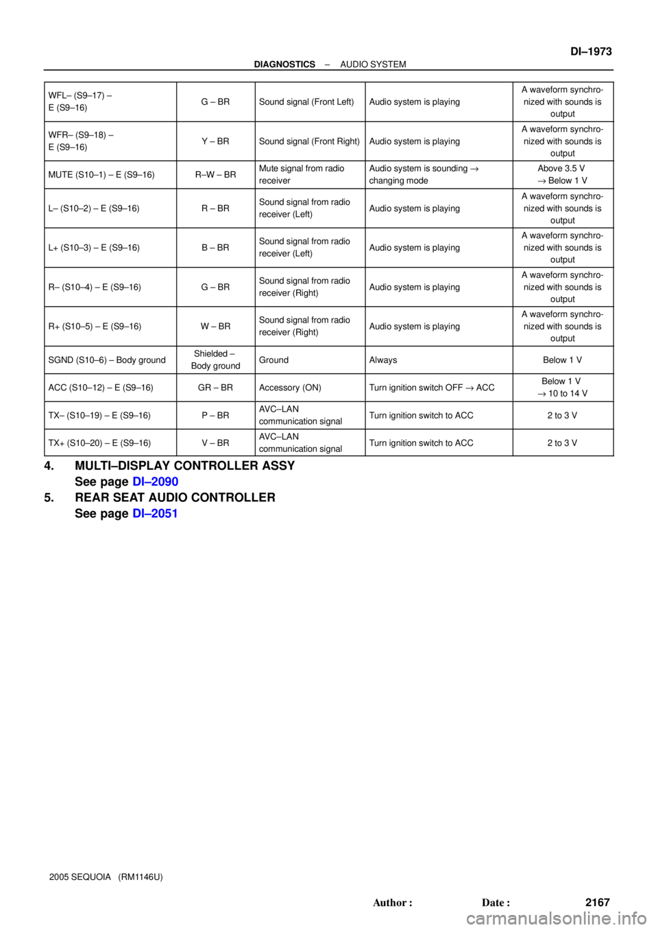
2005 SEQUOIA (RM1146U) WFL± (S9±17) ±
E (S9±16)
G ± BRSound signal (Front Left)Audio system is playing
A waveform synchro-
nized with sounds is
output
WFR± (S9±18) ±
E (S9±16)Y ± BRSound signal (Front Right)Audio system is playing
A waveform synchro-
nized with sounds is
output
MUTE (S10±1) ± E (S9±16)R±W ± BRMute signal from radio
receiverAudio system is sounding "
changing modeAbove 3.5 V
"Below 1 V
L± (S10±2) ± E (S9±16)R ± BRSound signal from radio
receiver (Left)Audio system is playing
A waveform synchro-
nized with sounds is
output
L+ (S10±3) ± E (S9±16)B ± BRSound signal from radio
receiver (Left)Audio system is playing
A waveform synchro-
nized with sounds is
output
R± (S10±4) ± E (S9±16)G ± BRSound signal from radio
receiver (Right)Audio system is playing
A waveform synchro-
nized with sounds is
output
R+ (S10±5) ± E (S9±16)W ± BRSound signal from radio
receiver (Right)Audio system is playing
A waveform synchro-
nized with sounds is
output
SGND (S10±6) ± Body groundShielded ±
Body groundGroundAlwaysBelow 1 V
ACC (S10±12) ± E (S9±16)GR ± BRAccessory (ON)Turn ignition switch OFF "ACCBelow 1 V
"10 to 14 V
TX± (S10±19) ± E (S9±16)P ± BRAVC±LAN
communication signalTurn ignition switch to ACC2 to 3 V
TX+ (S10±20) ± E (S9±16)V ± BRAVC±LAN
communication signalTurn ignition switch to ACC2 to 3 V
4. MULTI±DISPLAY CONTROLLER ASSY
See page DI±2090
5. REAR SEAT AUDIO CONTROLLER
See page DI±2051
Page 2181 of 4323

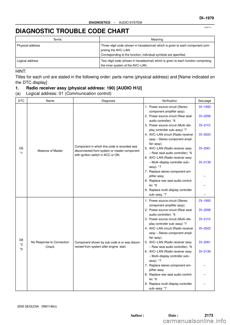
DID9T±01
± DIAGNOSTICSAUDIO SYSTEM
DI±1979
2173 Author�: Date�:
2005 SEQUOIA (RM1146U)
DIAGNOSTIC TROUBLE CODE CHART
TermsMeaning
Physical addressThree±digit code (shown in hexadecimal) which is given to each component com-
prising the AVC±LAN.
Corresponding to the function, individual symbols are specified.
Logical addressTwo±digit code (shown in hexadecimal) which is given to each function comprising
the inner system of the AVC±LAN.
HINT:
Titles for each unit are stated in the following order: parts name (physical address) and [Name indicated on
the DTC display]
1. Radio receiver assy (physical address: 190) [AUDIO H/U]
(a) Logical address: 01 (Communication control)
DTCNameDiagnosisVerificationSee page
D6
*1Absence of Master
Component in which this code is recorded was
disconnected from system or master component
with ignition switch in ACC or ON.
1. Power source circuit (Stereo
component amplifier assy).
2. Power source circuit (Rear seat
audio controller). *6
3. Power source circuit (Multi±dis-
play controller sub±assy) *7
4. AVC±LAN circuit (Radio receiver
assy ± Stereo component ampli-
fier assy).
5. AVC±LAN (Radio receiver assy
± Rear seat audio controller). *6
6. AVC±LAN (Radio receiver assy
± Multi±display controller sub±
assy). *7
7. Replace stereo component am-
plifier assy.
8. Replace rear seat audio control-
ler. *6
9. Replace multi±display controller
sub±assy. *7DI±1993
DI±2058
DI±2110
DI±2023
DI±2061
DI±2139
±
±
±
D8
*2
*5No Response to Connection
CheckComponent shown by sub code is or was discon-
nected from system after engine start.
1. Power source circuit (Stereo
component amplifier assy).
2. Power source circuit (Rear seat
audio controller). *6
3. Power source circuit (Multi±dis-
play controller sub±assy) *7
4. AVC±LAN circuit (Radio receiver
assy ± Stereo component ampli-
fier assy).
5. AVC±LAN (Radio receiver assy
± Rear seat audio controller). *6
6. AVC±LAN (Radio receiver assy
± Multi±display controller sub±
assy). *7
7. Replace stereo component am-
plifier assy.
8. Replace rear seat audio control-
ler. *6
9. Replace multi±display controller
sub±assy. *7DI±1993
DI±2058
DI±2110
DI±2023
DI±2061
DI±2139
±
±
±