Page 3026 of 4323
SA23I±04
R13426
F07263
F07264
F07265
SA±22
± SUSPENSION AND AXLEFRONT AXLE HUB
3018 Author�: Date�:
2005 SEQUOIA (RM1146U)
REMOVAL
1. REMOVE FRONT WHEEL
2. REMOVE GREASE CAP
Using a screwdriver and hammer, remove the grease cap.
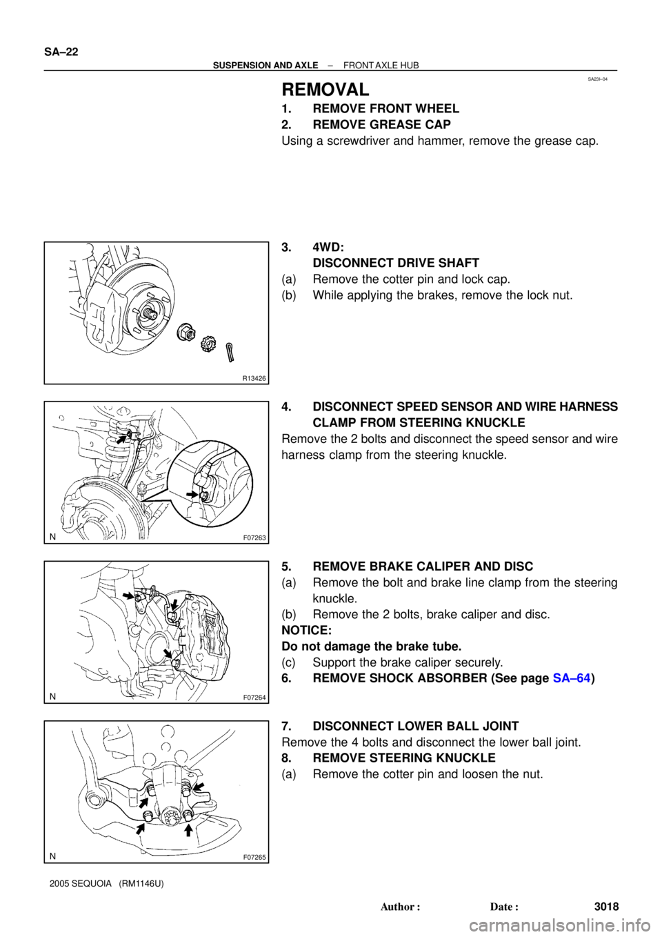
3. 4WD:
DISCONNECT DRIVE SHAFT
(a) Remove the cotter pin and lock cap.
(b) While applying the brakes, remove the lock nut.
4. DISCONNECT SPEED SENSOR AND WIRE HARNESS
CLAMP FROM STEERING KNUCKLE
Remove the 2 bolts and disconnect the speed sensor and wire
harness clamp from the steering knuckle.
5. REMOVE BRAKE CALIPER AND DISC
(a) Remove the bolt and brake line clamp from the steering
knuckle.
(b) Remove the 2 bolts, brake caliper and disc.
NOTICE:
Do not damage the brake tube.
(c) Support the brake caliper securely.
6. REMOVE SHOCK ABSORBER (See page SA±64)
7. DISCONNECT LOWER BALL JOINT
Remove the 4 bolts and disconnect the lower ball joint.
8. REMOVE STEERING KNUCKLE
(a) Remove the cotter pin and loosen the nut.
Page 3028 of 4323

DISASSEMBLY
1. 2WD:
REMOVE GREASE CAP
(a) Mount the axle hub in a soft ja")
SA145±08
R13215
SST
R13275
SST
SST SA±24
± SUSPENSION AND AXLEFRONT AXLE HUB
3020 Author�: Date�:
2005 SEQUOIA (RM1146U)
DISASSEMBLY
1. 2WD:
REMOVE GREASE CAP
(a) Mount the axle hub in a soft jaw vise.
HINT:
Close the vise until it holds hub bolts. Do not tighten further.
(b) Using a screwdriver, remove the grease cap.
2. 4WD:
REMOVE OIL SEAL (INSIDE)
(a) Mount the axle hub in a soft jaw vise.
HINT:
Close the vise until it holds hub bolts. Do not tighten further.
(b) Using a screwdriver, remove the oil seal (inside).
3. 2WD:
REMOVE LOCK NUT AND SPEED SENSOR ROTOR
(a) Using a chisel and hammer, loosen the staked part of the
lock nut.
NOTICE:
Be careful not to damage the bushing.
(b) Using SST, remove the lock nut.
SST 09318±12010
(c) Remove the speed sensor rotor.
NOTICE:
Take care not to scratch the serration of the speed sensor
rotor.
4. REMOVE AXLE HUB FROM STEERING KNUCKLE
(a) Remove the 4 bolts and shift the dust cover towards the
hub side (outside).
(b) Using SST, remove the axle hub from the steering
knuckle.
SST 09710±30021 (09710±03051),
09950±40011 (09951±04020, 09952±04010,
09953±04020, 09954±04010, 09955±04031,
09957±04010, 09958±04011)
(c) Remove the dust cover from the steering knuckle.
(d) 4WD:
Remove the bearing spacer and speed sensor rotor.
NOTICE:
Take care not to scratch the serration of the speed sensor
rotor.
5. REMOVE OIL SEAL (OUTSIDE)
Using a screwdriver, remove the oil seal (outside) from the
steering knuckle.
6. REMOVE BEARING FROM STEERING KNUCKLE
(a) Using snap ring pliers, remove the snap ring.
Page 3030 of 4323

REASSEMBLY
1. INSTALL NEW BEARING
(a")
SA146±08
R13277
SST
SST
R13278
SST
SST
R13279
SST
R13215
SST
R13418
SST SA±26
± SUSPENSION AND AXLEFRONT AXLE HUB
3022 Author�: Date�:
2005 SEQUOIA (RM1146U)
REASSEMBLY
1. INSTALL NEW BEARING
(a) Using SST and a press, install a new bearing to the steer-
ing knuckle.
SST 09527±17011, 09950±60020 (09951±00910)
(b) Using snap ring pliers, install a new snap ring.
2. INSTALL NEW OIL SEAL (OUTSIDE)
(a) Using SST and a plastic hammer, install a new oil seal
(outside).
SST 09223±15030, 09527±17011
(b) Coat MP grease to the oil seal lip.
3. INSTALL AXLE HUB TO STEERING KNUCKLE
(a) Install the dust cover to the steering knuckle with the 4
bolts.
Torque: 18 N´m (185 kgf´cm, 13 ft´lbf)
(b) Using SST and a press, install the axle hub to the steering
knuckle.
SST 09649±17010
4. INSTALL SPEED SENSOR ROTOR
NOTICE:
Do not scratch the serration of the speed sensor rotor.
5. 2WD:
INSTALL NEW LOCK NUT
(a) Using SST, install and torque a new lock nut to the axle
hub.
SST 09318±12010
Torque: 274 N´m (2,800 kgf´cm, 203 ft´lbf)
(b) Using a chisel and hammer, stake the lock nut.
6. 4WD:
INSTALL BEARING SPACER
Using SST and a press, install the bearing spacer.
SST 09950±60010 (09951±00650),
09950±70010 (09951±07150)
7. 2WD:
INSTALL GREASE CAP
Page 3032 of 4323

INSTALLATION
1. INSTALL STEERING KNUCKLE
(a) 4WD:
Insert the drive shaft into the axle hub and temp")
SA23J±05
SA±28
± SUSPENSION AND AXLEFRONT AXLE HUB
3024 Author�: Date�:
2005 SEQUOIA (RM1146U)
INSTALLATION
1. INSTALL STEERING KNUCKLE
(a) 4WD:
Insert the drive shaft into the axle hub and temporarily tighten the nut.
NOTICE:
Be careful not to damage the oil seal and drive shaft boot.
(b) Connect the steering knuckle to the upper suspension arm.
(c) Install the nut and a new cotter pin.
If the holes for the cotter pin are not aligned, tighten the nut further up to 60°.
Torque: 105 N´m (1,100 kgf´cm, 77 ft´lbf)
2. CONNECT LOWER BALL JOINT
Connect the lower ball joint to the steering knuckle with the 4 bolts.
Torque: 65 N´m (663 kgf´cm, 48 ft´lbf)
3. INSTALL SHOCK ABSORBER (See page SA±70)
4. INSTALL BRAKE CALIPER
(a) Install the disc, brake caliper and 2 bolts.
Torque: 123 N´m (1,250 kgf´cm, 90 ft´lbf)
(b) Install the brake line clamp to the steering knuckle with the bolt.
Torque: 28 N´m (285 kgf´cm, 21 ft´lbf)
5. CONNECT SPEED SENSOR AND WIRE HARNESS CLAMP
Connect the speed sensor and wire harness clamp to the steering knuckle with the 2 bolts.
Torque: 8.0 N´m (82 kgf´cm, 71 ft´lbf)
6. 4WD:
INSTALL DRIVE SHAFT LOCK NUT
(a) While applying the brakes, tighten the nut.
Torque: 235 N´m (2,400 kgf´cm, 173 ft´lbf)
(b) Install the lock cap and a new cotter pin.
If the holes for the cotter pin are not aligned, tighten the nut further up to 60°.
7. INSTALL GREASE CAP
8. INSTALL FRONT WHEEL
Torque: 110 N´m (1,150 kgf´cm, 83 ft´lbf)
9. DEPRESS BRAKE PEDAL SEVERAL TIMES
10. CHECK FRONT WHEEL ALIGNMENT (See page SA±4)
11. CHECK SPEED SENSOR SIGNAL (See page DI±899)
12. PERFORM ZERO POINT CALIBRATION OF STEERING ANGLE, MASTER CYLINDER PRES-
SURE, YAW RATE AND DECELERATION SENSORS (See page DI±897)
Page 3075 of 4323
SA183±05
F07268
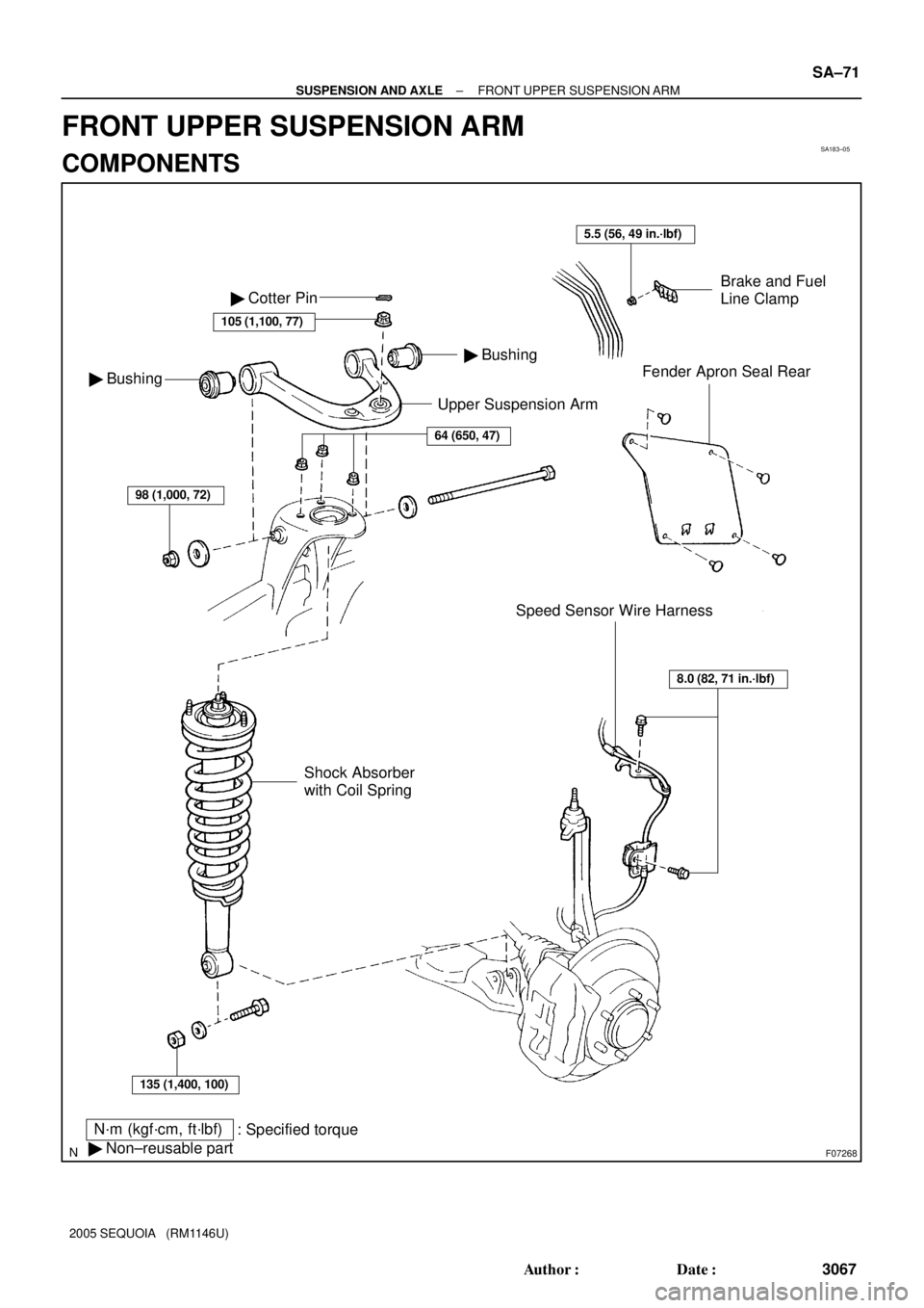
Upper Suspension Arm
N´m (kgf´cm, ft´lbf)
: Specified torque
� Non±reusable part
Brake and Fuel
Line Clamp
Fender Apron Seal Rear
Speed Sensor Wire Harness � Bushing
� Bushing � Cotter Pin
105 (1,100, 77)
64 (650, 47)
98 (1,000, 72)
135 (1,400, 100)
Shock Absorber
with Coil Spring
8.0 (82, 71 in.´lbf)
5.5 (56, 49 in.´lbf)
± SUSPENSION AND AXLEFRONT UPPER SUSPENSION ARM
SA±71
3067 Author�: Date�:
2005 SEQUOIA (RM1146U)
FRONT UPPER SUSPENSION ARM
COMPONENTS
Page 3076 of 4323
SA23W±03
R13196
SST
F07269
F07270
SA±72
± SUSPENSION AND AXLEFRONT UPPER SUSPENSION ARM
3068 Author�: Date�:
2005 SEQUOIA (RM1146U)
REMOVAL
1. REMOVE SHOCK ABSORBER WITH COIL SPRING
(See page SA±64)
2. DISCONNECT SPEED SENSOR WIRE HARNESS
CLAMPS
Remove the 2 bolts and speed sensor wire harness clamps
from the steering knuckle and upper suspension arm.
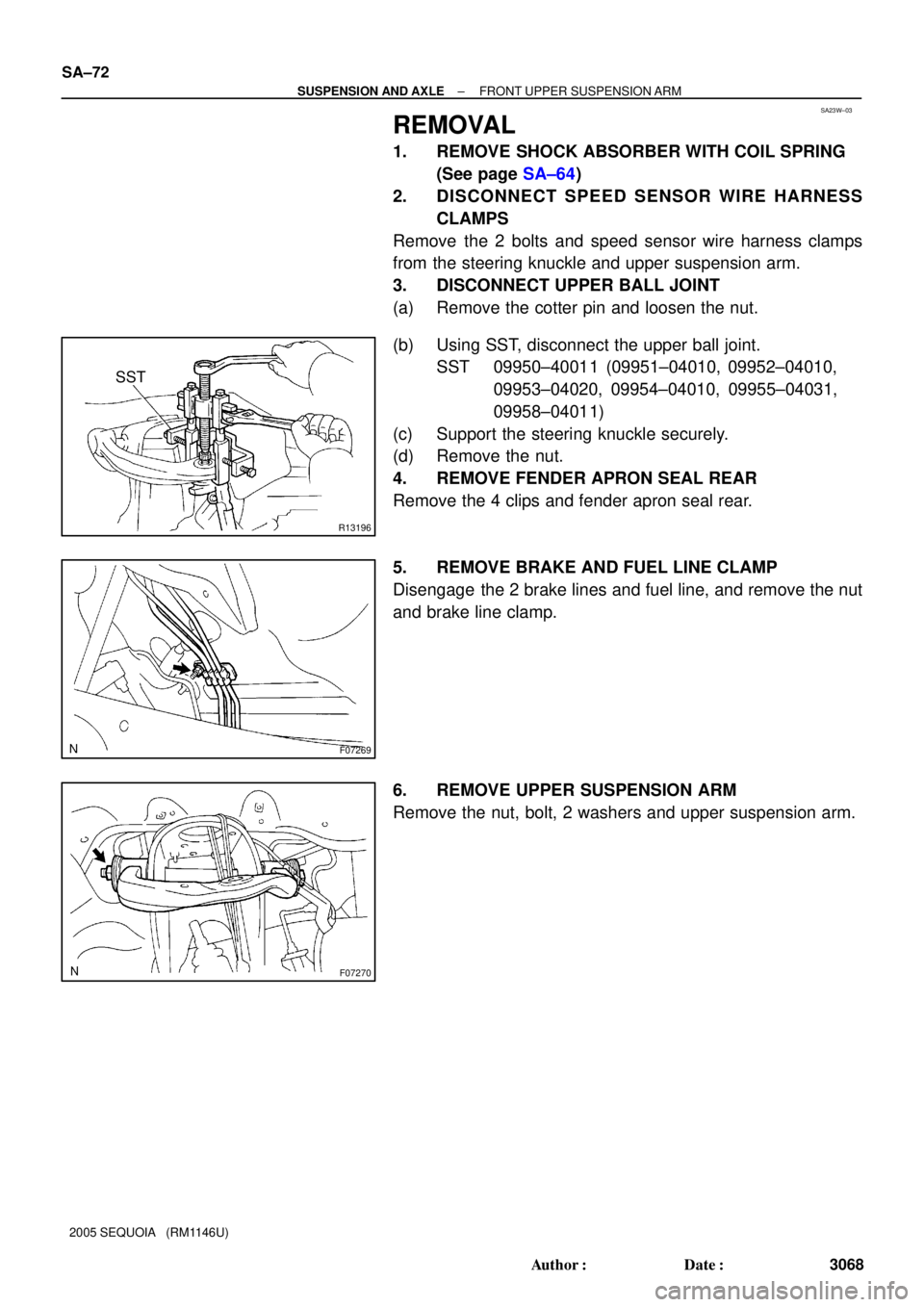
3. DISCONNECT UPPER BALL JOINT
(a) Remove the cotter pin and loosen the nut.
(b) Using SST, disconnect the upper ball joint.
SST 09950±40011 (09951±04010, 09952±04010,
09953±04020, 09954±04010, 09955±04031,
09958±04011)
(c) Support the steering knuckle securely.
(d) Remove the nut.
4. REMOVE FENDER APRON SEAL REAR
Remove the 4 clips and fender apron seal rear.
5. REMOVE BRAKE AND FUEL LINE CLAMP
Disengage the 2 brake lines and fuel line, and remove the nut
and brake line clamp.
6. REMOVE UPPER SUSPENSION ARM
Remove the nut, bolt, 2 washers and upper suspension arm.
Page 3078 of 4323

INSTALLATION
1. INSTALL UPPER SUSPENSION ARM
Install the upper suspension arm with the 2")
SA187±06
SA±74
± SUSPENSION AND AXLEFRONT UPPER SUSPENSION ARM
3070 Author�: Date�:
2005 SEQUOIA (RM1146U)
INSTALLATION
1. INSTALL UPPER SUSPENSION ARM
Install the upper suspension arm with the 2 washers, bolt and nut.
Torque: 98 N´m (1,000 kgf´cm, 72 ft´lbf)
HINT:
After stabilizing the suspension, torque the nut.
2. INSTALL BRAKE AND FUEL LINE CLAMP
Torque: 5.5 N´m (56 kgf´cm, 49 in.´lbf)
3. INSTALL FENDER APRON SEAL REAR
4. CONNECT UPPER BALL JOINT
(a) Connect the upper ball joint to the upper suspension arm.
(b) Install the nut and a new cotter pin.
If the holes for the cotter pin are not aligned, tighten the nut further up to 60°.
Torque: 105 N´m (1,100 kgf´cm, 77 ft´lbf)
5. CONNECT SPEED SENSOR WIRE HARNESS CLAMPS
Torque: 8.0 N´m (82 kgf´cm, 71 in.´lbf)
6. INSTALL SHOCK ABSORBER WITH COIL SPRING (See page SA±70)
7. CHECK FRONT WHEEL ALIGNMENT (See page SA±4)
8. PERFORM ZERO POINT CALIBRATION OF STEERING ANGLE, MASTER CYLINDER PRES-
SURE, YAW RATE AND DECELERATION SENSORS (See page DI±897)
Page 3084 of 4323

INSTALLATION
1. INSTALL LOWER SUSPENSION ARM TO")
SA23Y±05
R13282
MatchmarksMatchmarks
F07278
AC
B SA±80
± SUSPENSION AND AXLEFRONT LOWER SUSPENSION ARM
3076 Author�: Date�:
2005 SEQUOIA (RM1146U)
INSTALLATION
1. INSTALL LOWER SUSPENSION ARM TO CHASSIS
FRAME
Install the lower suspension arm with the 2 cams, bolts and cam
plates while slightly shifting the power steering gear rearward.
Torque: 130 N´m (1,325 kgf´cm, 96 ft´lbf)
NOTICE:
Do not damage the power steering gear tubes.
HINT:
After stabilizing the suspension, align the matchmarks on the
front and rear cam plates and chassis frame, and torque the
bolts.
2. CONNECT LOWER BALL JOINT TO LOWER SUSPEN-
SION ARM
Connect the lower ball joint and install the nut and a new cotter
pin.
Torque: 159 N´m (1,621 kgf´cm, 117 ft´lbf)
If the holes for the cotter pin are not aligned, tighten the nut fur-
ther up to 60°.
3. CONNECT SHOCK ABSORBER TO LOWER SUSPEN-
SION ARM
Torque: 135 N´m (1,400 kgf´cm, 100 ft´lbf)
4. CONNECT STABILIZER BAR LINK TO LOWER SUS-
PENSION ARM
Torque: 69 N´m (700 kgf´cm, 51 ft´lbf)
HINT:
If the ball joint turns together with the nut, use a hexagon (6 mm)
wrench to hold the stud.
5. INSTALL POWER STEERING GEAR
Torque:
A bolt: 165 N´m (1,700 kgf´cm, 122 ft´lbf)
B nut: 130 N´m (1,350 kgf´cm, 96 ft´lbf)
C bolt and nut: 165 N´m (1,700 kgf´cm, 122 ft´lbf)
6. CONNECT RH AND LH TIE ROD ENDS
Connect the RH and LH tie rod ends to the lower ball joints with
the nuts and new cotter pins.
Torque: 91 N´m (930 kgf´cm, 67 ft´lbf)
If the holes for the cotter pin are not aligned, tighten the nut fur-
ther up to 60°.
7. INSTALL RH AND LH FRONT WHEELS
Torque: 110 N´m (1,150 kgf´cm, 83 ft´lbf)
8. CHECK FRONT WHEEL ALIGNMENT (See page
SA±4)
9. PERFORM ZERO POINT CALIBRATION OF STEER-
ING ANGLE, MASTER CYLINDER PRESSURE, YAW
RATE AND DECELERATION SENSORS (See page
DI±897)