Page 3163 of 4323

(c) Measure the vehicle height (C ± D measurement) on")
F19904
C
D
F16848
F16826Lock Nut
± SUSPENSION AND AXLEELECTRONIC MODULATED AIR SUSPENSION
SA±159
3155 Author�: Date�:
2005 SEQUOIA (RM1146U)
(c) Measure the vehicle height (C ± D measurement) on the
right side and left side.
Standard vehicle height value: See page SA±4
(d) If the value in (c) differs from the vehicle height (C ± D
measurement), adjust it by following the procedures be-
low:
(1) Loosen the nut.
(2) Move the height control sensor link back and forth
along the slotted hole of the bracket.
HINT:
Move the link toward the front of the vehicle to raise vehicle
height. Move the link toward the rear of the vehicle to lower ve-
hicle height. Every 1 mm (0.039 in.) change in the installation
position of the link causes vehicle height to change by approxi-
mately 2 mm (0.079 in.).
(3) Tighten the nut.
Torque: 5.4 N´m (55 kgf´cm, 48 in.´lbf)
(e) If the vehicle height cannot be adjusted by performing (d),
adjust it again by following the procedures below.
(1) Loosen the 2 lock nuts of the height control sensor
link.
(2) Adjust the vehicle height to the vehicle height (C ±
D measurement) by turning the link.
HINT:
Extend the link to raise vehicle height. Shorten the link to lower
vehicle height. Every 1 turn of the link causes vehicle height to
change by approximately 4 mm (0.157 in.).
(3) Tighten the 2 lock nuts.
Torque: 5.4 N´m (55 kgf´cm, 48 in.´lbf)
Page 3172 of 4323
SA1I9±03
F16849
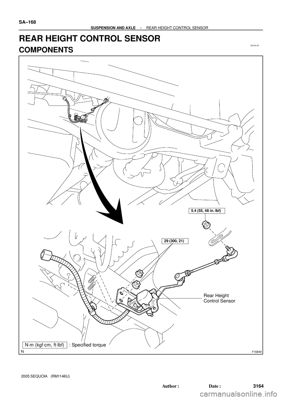
N´m (kgf´cm, ft´lbf) : Specified torque
29 (300, 21)
5.4 (55, 48 in.´lbf)
Rear Height
Control Sensor
SA±168
± SUSPENSION AND AXLEREAR HEIGHT CONTROL SENSOR
3164 Author�: Date�:
2005 SEQUOIA (RM1146U)
REAR HEIGHT CONTROL SENSOR
COMPONENTS
Page 3173 of 4323
SA2D3±01
F16835Matchmarks
F16836
± SUSPENSION AND AXLEREAR HEIGHT CONTROL SENSOR
SA±169
3165 Author�: Date�:
2005 SEQUOIA (RM1146U)
REMOVAL
1. DISCONNECT CONNECTOR
2. DISCONNECT HEIGHT CONTROL SENSOR LINK
(a) Put matchmarks on the height control sensor link and
bracket.
(b) Remove the nut and disconnect the sensor link.
Torque: 5.4 N´m (55 kgf´cm, 48 in.´lbf)
3. REMOVE REAR HEIGHT CONTROL SENSOR
(a) Disconnect the wire harness clamp.
(b) Remove the 2 bolts and rear height control sensor.
Torque: 29 N´m (300 kgf´cm, 21 ft´lbf)
Page 3174 of 4323
SA1IB±03
SA±170
± SUSPENSION AND AXLEREAR HEIGHT CONTROL SENSOR
3166 Author�: Date�:
2005 SEQUOIA (RM1146U)
INSTALLATION
Installation is in the reverse order of removal (See page SA±169).
Page 3190 of 4323
BR10E±04
F16310
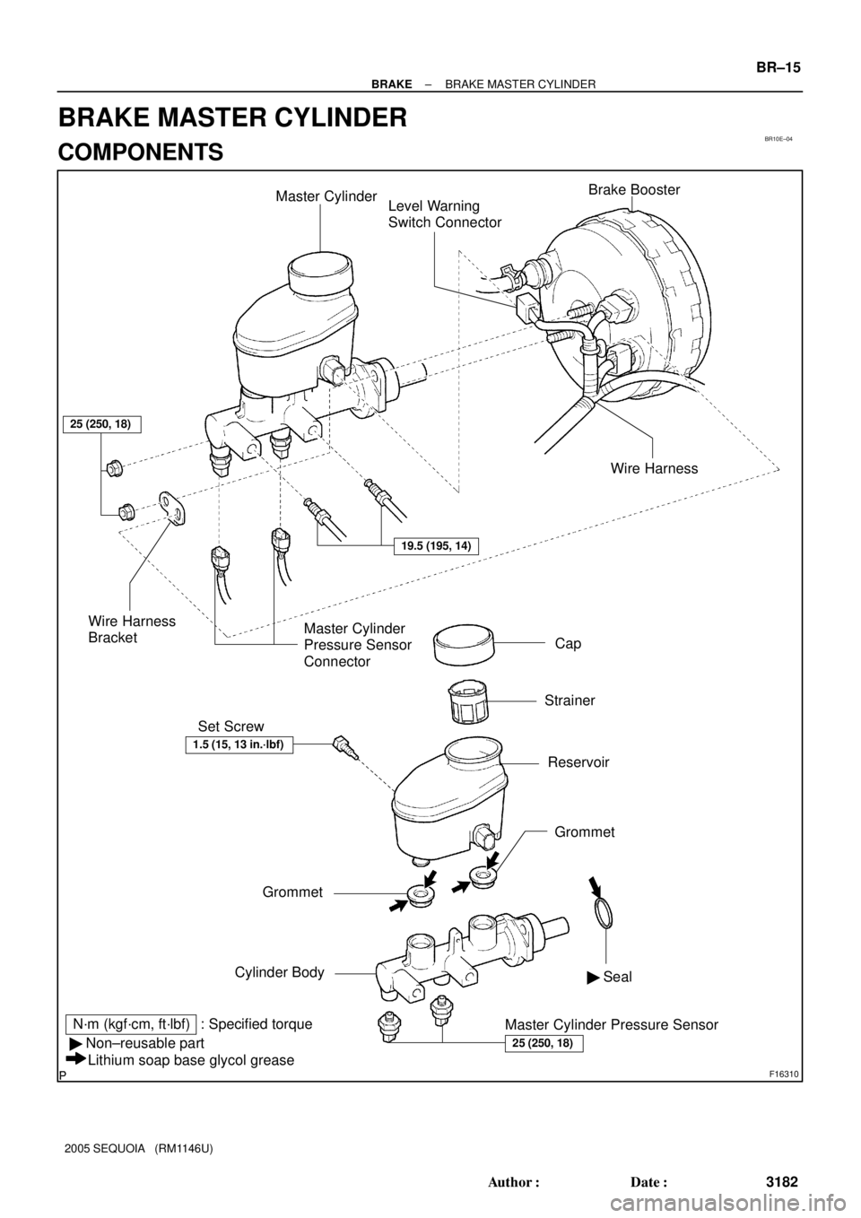
Master Cylinder
Level Warning
Switch ConnectorBrake Booster
Cap
Strainer
Reservoir Set Screw
Grommet
Cylinder Body
N´m (kgf´cm, ft´lbf) : Specified torque
� Non±reusable part
Lithium soap base glycol greaseWire Harness
BracketMaster Cylinder
Pressure Sensor
Connector
Master Cylinder Pressure Sensor� Seal
25 (250, 18)
25 (250, 18)
19.5 (195, 14)
Wire Harness
1.5 (15, 13 in.´lbf)
Grommet
± BRAKEBRAKE MASTER CYLINDER
BR±15
3182 Author�: Date�:
2005 SEQUOIA (RM1146U)
BRAKE MASTER CYLINDER
COMPONENTS
Page 3191 of 4323
BR08U±05
F16312
F16313
BR±16
± BRAKEBRAKE MASTER CYLINDER
3183 Author�: Date�:
2005 SEQUOIA (RM1146U)
REMOVAL
1. DRAW OUT FLUID WITH SYRINGE
NOTICE:
Wash the brake fluid off immediately if it comes into con-
tact with any painted surface.
2. DISCONNECT LEVEL WARNING SWITCH CONNEC-
TOR
3. DISCONNECT 2 MASTER CYLINDER PRESSURE
SENSOR CONNECTORS
4. DISCONNECT WIRE HARNESS
Using a clip remover, disconnect the wire harness from the wire
harness bracket.
5. DISCONNECT BRAKE LINES
Using SST, disconnect the 2 brake lines from the master cylin-
der.
SST 09023±38201
Torque: 19.5 N´m (195 kgf´cm, 14 ft´lbf)
6. REMOVE MASTER CYLINDER
(a) Remove the 2 nuts and wire harness bracket.
Torque: 25 N´m (250 kgf´cm, 18 ft´lbf)
(b) Pull out the master cylinder from the brake booster.
Page 3192 of 4323
BR1ND±02
± BRAKEBRAKE MASTER CYLINDER
BR±17
3184 Author�: Date�:
2005 SEQUOIA (RM1146U)
DISASSEMBLY
1. REMOVE RESERVOIR
(a) Remove the set screw and pull out the reservoir.
Torque: 1.5 N´m (15 kgf´cm, 13 in.´lbf)
(b) Remove the cap and strainer from the reservoir.
2. REMOVE 2 GROMMETS
3. REMOVE SEAL
4. REMOVE 2 MASTER CYLINDER PRESSURE SENSORS
Torque: 25 N´m (250 kgf´cm, 18 ft´lbf)
Page 3194 of 4323
BR08Y±07
± BRAKEBRAKE MASTER CYLINDER
BR±19
3186 Author�: Date�:
2005 SEQUOIA (RM1146U)
INSTALLATION
Installation is in the reverse order of removal (See page BR±16).
HINT:
�After installation, fill the brake reservoir with brake fluid and bleed brake system (See page BR±4).
�Check for leaks.
NOTICE:
In case of replacing the master cylinder assembly or master cylinder pressure sensor, perform the
zero point calibration of the steering angle, master cylinder pressure, yawrate and deceleration sen-
sors (See page DI±897).